Trace Metals Analysis in Petroleum Products: Essential Methods, Challenges, and Innovations for Researchers
This article provides a comprehensive overview of trace metals analysis in petroleum products, addressing critical needs for researchers and scientists.
Trace Metals Analysis in Petroleum Products: Essential Methods, Challenges, and Innovations for Researchers
Abstract
This article provides a comprehensive overview of trace metals analysis in petroleum products, addressing critical needs for researchers and scientists. It covers the foundational reasons for analysis—from catalyst poisoning and corrosion to environmental impact—and explores advanced methodological approaches like ICP-MS and ICP-OES. The content delves into practical troubleshooting for complex matrices and contamination, and offers a comparative evaluation of analytical techniques to ensure data validity and regulatory compliance, providing a complete guide for accurate and efficient elemental analysis.
Why Trace Metals Matter: Foundational Concepts and Impact in Petroleum Systems
Trace metals, present in crude oil at concentrations ranging from parts-per-million (ppm) to parts-per-trillion (ppt), are critical determinants in the production, refining, and distribution of quality petroleum products [1]. Understanding, monitoring, and managing trace metal levels is not merely a quality control step but a fundamental practice with a direct impact on refinery yields, catalyst preservation, and infrastructure protection [1]. These metals, including Nickel (Ni), Vanadium (V), Iron (Fe), and Arsenic (As), originate from the crude oil itself and can cause severe operational challenges such as catalyst poisoning, corrosion, and product quality degradation, ultimately affecting profitability and safety [1] [2]. This application note, framed within broader research on trace metals analysis in petroleum products, provides a detailed framework for their accurate determination, supporting researchers and scientists in mitigating these risks.
The presence of trace metals poses a constant challenge throughout the hydrocarbon value chain. In refining processes, metals like nickel and vanadium are notorious catalyst poisons, directly reducing the efficiency and lifespan of expensive catalytic cracking units [1]. Furthermore, they can lead to the formation of undesirable compounds during processing, negatively affecting the properties of the final refined products. Beyond catalysts, trace metals contribute to corrosion problems within pipelines, storage tanks, and other infrastructure, creating significant safety risks and potential environmental liabilities [1]. Therefore, a robust analytical strategy for trace metal content is indispensable for ensuring operational integrity, optimizing process economics, and guaranteeing final product specification compliance.
Analytical Techniques for Trace Metal Determination
A variety of sophisticated analytical techniques are employed for the detection and quantification of trace metals in petroleum products and related hydrocarbons. The choice of technique depends on the required sensitivity, the specific elements of interest, and the sample matrix.
The following table summarizes the primary techniques used in the industry for trace metals analysis:
Table 1: Analytical Techniques for Trace Metals in Petroleum Products
| Technique | Full Name | Typical Detection Levels | Key Principles and Applications |
|---|---|---|---|
| ICP-MS [1] [3] [4] | Inductively Coupled Plasma Mass Spectrometry | ppt to ppb | Combines a high-temperature ICP plasma with a mass spectrometer. Offers exceptional sensitivity and low detection limits for a wide range of elements. Ideal for ultra-trace analysis. |
| ICP / ICP-AES [1] [4] | Inductively Coupled Plasma Atomic Emission Spectrometry | ppb to ppm | Uses ICP to excite atoms, which then emit light at characteristic wavelengths. A common, versatile technique for multi-element analysis with a wide dynamic range. |
| XRF [5] | X-ray Fluorescence | ~0.01% (100 ppm) and higher | A non-destructive technique that measures fluorescent X-rays emitted from a sample. Suitable for direct analysis of solids like petroleum coke, but less sensitive than plasma-based methods. |
| CVAFS [4] | Cold Vapor Atomic Fluorescence Spectrometry | ppt levels for Hg | A highly selective and sensitive technique specifically optimized for the accurate measurement of mercury at extremely low concentrations. |
| AA [1] | Atomic Absorption Spectrometry | ppb to ppm | A traditional technique that measures the absorption of light by free atoms in the gaseous state. Can be configured as Graphite Furnace (GFAA) for enhanced sensitivity [6]. |
Comparison of Method Performance
The capabilities of these techniques can be further understood by comparing their practical application in standardized test methods.
Table 2: Standardized Test Methods for Trace Metals in Hydrocarbons
| Standard Method | Technique | Application Focus | Key Analyte Metals |
|---|---|---|---|
| ASTM D5708 [1] | ICP | Nickel, Vanadium, Iron in Crude Oil & Residual Fuel | Ni, V, Fe |
| ASTM D5863 [1] | Various | Trace Metals, Nickel, Vanadium, Iron, Sodium | Ni, V, Fe, Na, Others |
| ASTM D5185 [1] | ICP | Additive Elements, Wear Metals in Lubricants | Additive and wear metals |
| WSC-CAM-IIID [6] | ICP-MS | Trace Metals in Environmental Samples | A wide range of trace metals |
| EPA Method 200.7 [7] | ICP-AES | Metals in Water and Wastes | As, Tl, V, and others |
| USEPA SW-846 7470/7471 [6] | CVAA | Mercury by Cold Vapor | Hg |
Detailed Experimental Protocols
This section provides a step-by-step Standard Operating Procedure (SOP) for determining trace elements using ICP-MS, adapted for challenging matrices like petroleum derivatives and hydrothermal fluids, which exhibit high variability in salinity and pH [3].
Protocol: Trace Metals Analysis by ICP-MS
1. Principle: Liquid samples are nebulized, and the resulting aerosol is transported to an argon plasma torch where elements are atomized and ionized. The ions are then separated by a mass spectrometer based on their mass-to-charge ratio (m/z) and detected [3].
2. Scope: This protocol is applicable for the quantitative determination of trace elements in digested hydrocarbon samples, crude oils, refined products, and related aqueous matrices. Calibration curves are typically linear from 0.01 to 100 μg/L [3].
3. Equipment and Reagents:
- Agilent 7900 ICP-MS or equivalent system [3]
- Autosampler and peristaltic pump
- High-purity argon gas
- High-purity nitric acid and water
- Single-element and multi-element calibration standards
- Certified Reference Materials (CRMs) for quality control
4. Sample Preparation:
- Liquid Hydrocarbons: Dilution with a suitable organic solvent (e.g., xylene, kerosene) may be sufficient. For more complex matrices or to achieve lower detection limits, acid digestion or microwave-assisted digestion may be required to fully decompose the organic matrix and extract metals into an aqueous phase [1] [4].
- Aqueous Samples: Filter samples if particulate matter is present. Acidify with high-purity nitric acid to a pH <2 to preserve metal content and prevent adsorption to container walls [3].
- Crucial Precaution: To minimize contamination, use acid-washed labware (e.g., plastic vials over glass to prevent leaching of Sb, Zn, Mn, Fe, Ba). Avoid colored plastics, as dyes can leach interfering elements like Cu, Fe, Zn, and Cd [3].
5. Instrumental Analysis:
- Instrument Setup: Establish operational conditions as optimized for the specific instrument. Key parameters include RF power, carrier gas flow, and lens settings. A collision cell pressurized with Helium (He) is used to reduce polyatomic interferences [3].
- Calibration: Analyze a series of multi-element calibration standards to establish a calibration curve for each target analyte.
- Quality Control: Include procedural blanks, continuing calibration verification standards, and Certified Reference Materials (CRMs) in every analytical batch to ensure accuracy and precision.
- Sample Analysis: Introduce prepared samples into the ICP-MS via the autosperistaltic pump and autosampler. The detector will count the ions and report results in counts per second (CPS), which are converted to concentration units via the calibration curve [3].
6. Data Analysis: The instrument software calculates concentrations based on the calibration curve. Results must be corrected for any dilution factors applied during sample preparation. A quality control check is mandatory; results for CRMs must fall within certified ranges, and blank values must be acceptably low.
Advanced Methodology: XRF Analysis for Solid Carbon Materials
For solid samples like petroleum coke, X-ray Fluorescence (XRF) offers a non-destructive alternative. A modern XRF method using a fundamental parameters mode (FPM) and an additive technique has been developed to overcome the challenge of low sensitivity to carbon atoms [5].
Workflow:
- Initial Analysis (FPM1): Analyze the homogeneous carbon sample (e.g., ground petroleum coke). The result provides the ratio of elements present, normalized to 100% [5].
- Addition of Spike: Add a known small mass (ma) of a selected element (A), such as in the form of CaCO₃, to a known mass (M₀) of the sample. Homogenize the mixture thoroughly [5].
- Second Analysis (FPM2): Analyze the spiked sample to get new mass fractions for all elements [5].
- Calculation: The true mass fraction of an element B (ZB) can be calculated using the formula:
Z_B = (Y_B / Y_A) * (m_a / M_0)[5], where YB and Y_A are the mass fractions of B and the additive A from the FPM2 analysis. This method is highly resistant to variations in sample preparation and density [5].
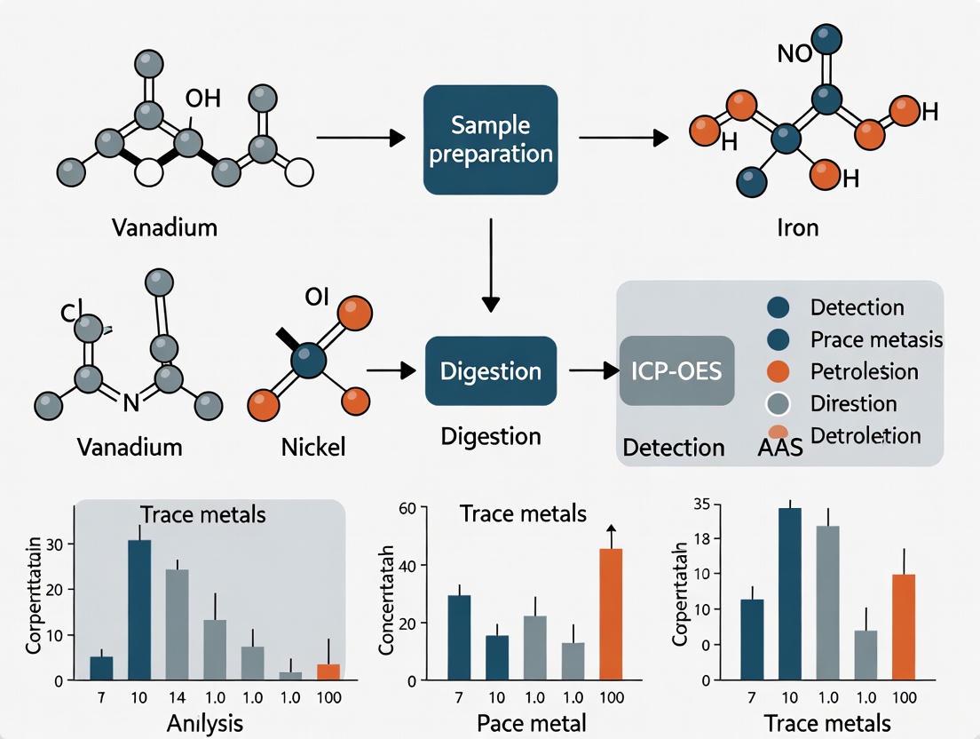
Visualizing the Analytical Workflow
The logical progression from sample receipt to data reporting is outlined in the following workflow diagram, which integrates the two primary protocols discussed.
The Scientist's Toolkit: Essential Research Reagents and Materials
Successful trace metals analysis requires meticulously selected materials and reagents to prevent contamination and ensure accuracy.
Table 3: Essential Research Reagents and Materials for Trace Metals Analysis
| Item | Function / Purpose | Critical Notes |
|---|---|---|
| High-Purity Nitric Acid [3] | Primary reagent for sample digestion and acidification of aqueous samples. | Essential for digesting organic matrices and preserving samples. Must be trace metal grade to avoid introducing contaminants. |
| Single-Element Stock Standards [3] | Used for the preparation of instrument calibration curves and quality control check standards. | 1000 mg/L stocks are typical. Used to spike samples in additive methods (e.g., XRF) [5]. |
| Certified Reference Materials (CRMs) | To verify method accuracy and precision for a specific sample matrix (e.g., fuel oil, crude). | A cornerstone of quality assurance. Results for CRMs must fall within certified uncertainty ranges. |
| Multi-Element Calibration Standard [3] | For initial instrument calibration and ongoing calibration verification during analysis. | Covers all analytes of interest. A continuing calibration verification standard is analyzed periodically to monitor instrument drift. |
| Helium Gas (He) [3] | Used as a non-reactive gas in the ICP-MS collision cell. | Preferentially removes larger polyatomic ions via collision, resolving spectral interferences (e.g., ³⁵Cl¹⁶O⁺ on ⁵¹V⁺). |
| Acid-Washed Plastic Vials & Tips [3] | For sample storage and handling throughout the preparation and analysis process. | Preferred over glass to prevent leaching. Non-colored plastic is mandatory to avoid contamination from dyes (leaching Cu, Fe, Zn, Cd). |
| Argon Gas (Ar) [3] | Sustains the inductively coupled plasma and acts as the carrier gas for the sample aerosol. | Must be of high purity to maintain plasma stability and minimize background noise. |
Regulatory and Industrial Context
Trace metals analysis is not only a technical necessity but also a regulatory imperative. In the United States, several key statutes govern the discharge and disposal of metals, influencing testing requirements for refinery wastes and wastewater.
- Resource Conservation and Recovery Act (RCRA): Focuses on the disposal of solid and hazardous waste, regulating the "RCRA 8" metals: Arsenic (As), Barium (Ba), Cadmium (Cd), Chromium (Cr), Lead (Pb), Mercury (Hg), Selenium (Se), and Silver (Ag) [4].
- Clean Water Act (CWA) / NPDES: Regulates the discharge of pollutants into surface waters through the National Pollutant Discharge Elimination System (NPDES) permit program, which sets limits on metal concentrations in wastewater [4].
- Safe Drinking Water Act (SDWA): Authorizes the EPA to set and enforce limits on contaminants, including metals like lead and copper, in public drinking water systems [4].
From an industrial perspective, comprehensive trace metal testing programs enable refineries to manage catalyst performance, protect infrastructure from corrosion, and ensure the quality of final products, thereby directly impacting profitability and operational safety [1].
In the complex matrix of petroleum products, the presence and concentration of specific trace metals serve as critical indicators for processing challenges, product quality, and catalyst viability. The analysis of nickel (Ni), vanadium (V), iron (Fe), sodium (Na), and arsenic (As) is particularly crucial for researchers and development professionals in the petroleum industry. These metals, though typically present at trace levels, exert disproportionately large effects on refining operations and final product specifications. This application note details the specific impacts of these key metals and provides standardized protocols for their accurate determination, supporting advanced research in petroleum characterization.
Metal Impacts and Analytical Significance
The following table summarizes the specific roles and impacts of each metal in petroleum processing and products.
Table 1: Specific Impacts of Key Metals in Petroleum Products
| Metal | Primary Impacts & Significance | Typical Concentration Ranges | Analytical Challenges |
|---|---|---|---|
| Nickel (Ni) | - Acts as a poison to hydrogenation catalysts [8]- Forms stable porphyrin complexes [8]- Indicator of crude oil maturity & origin | - Complex matrix interference [8]- Requires species-specific recovery [8] | |
| Vanadium (V) | - Causes degradation of catalyst activity [8]- Forms abrasive vanadium oxide deposits [8]- Corrosive to turbine blades | - Distributed among diverse ligated forms [8]- Poor identification of chemical binding [8] | |
| Iron (Fe) | - Indicates corrosion in pipelines and storage tanks- Affects product color and stability- Can form abrasive particulates | - Spectral interferences (e.g., 40Ar16O+, 40Ca16O+) [9] | |
| Sodium (Na) | - Causes catalyst deactivation- Promotes corrosion at high temperatures- Forms deposits in refinery equipment | - Particulate precipitation issues [10]- Requires representative sampling | |
| Arsenic (As) | - Potent catalyst poison in refining processes- Environmental and health concern in final products- Affects fuel cell performance | - Severe spectral interference (40Ar35Cl+, 40Ca35Cl+) [9] |
Analytical Methodologies
Sample Preparation Protocols
3.1.1 Direct Dilution Protocol
- Application: Suitable for homogeneous petroleum samples without particulate matter.
- Procedure: Dilute 0.5 g of crude oil or petroleum product in 10 mL of tetrahydrofuran (THF) with vigorous shaking for 2 minutes [8]. THF is preferred for its ability to retain the hydrocarbon mixture.
- Limitations: Risk of missing the isolation of metal-containing particulates; not suitable for samples with suspended solids [8].
3.1.2 Acid Digestion and Dry Ashing Protocol
- Application: Required for total metal content determination, especially for samples with particulates.
- Procedure:
- Weigh 2 g of sample into a quartz crucible
- Heat gradually to 550°C in a muffle furnace for 6-12 hours until complete ashing
- Dissolve residue in 5% nitric acid (HNO₃)
- Dilute to final volume for analysis [10]
- Quality Control: Include method blanks, duplicates, and certified reference materials with each batch.
3.1.3 Solidification Technique for XRF Analysis
- Application: Prevents particulate settling during EDXRF analysis.
- Procedure: Mix crude oil with solidification agent at 5:1 ratio to immobilize particulates in situ, then analyze the solid pellet directly [10].
- Advantages: Mitigates sedimentation effects, provides more representative analysis of heterogeneous samples.
Instrumental Analysis Methods
Table 2: Comparison of Analytical Techniques for Metal Determination
| Technique | Principles | Detection Limits | Applicable Standards | Advantages | Limitations |
|---|---|---|---|---|---|
| ICP-MS | Inductively Coupled Plasma Mass Spectrometry | Sub-ppb | SW-846 6020B [6] | High sensitivity, multi-element capability | Polyatomic interferences [9] |
| ICP-OES | Inductively Coupled Plasma Optical Emission Spectrometry | Low-ppb | SW-846 6010D [6], ASTM D5708 [10] | Robust for complex matrices | Requires sample digestion [10] |
| EDXRF | Energy-Dispersive X-Ray Fluorescence | ~1 ppm | ASTM D4294 [10] | Minimal sample prep, direct analysis | Limited sensitivity for low concentrations [10] |
| GFAAS | Graphite Furnace Atomic Absorption Spectrometry | Sub-ppb | SW-846 7010 [6] | Excellent for limited sample volumes | Single-element analysis, slower throughput |
Interference Mitigation Strategies
Modern ICP-MS systems employ advanced interference removal technologies to address polyatomic interferences that compromise accuracy [9]:
- Dynamic Reaction Cell (DRC): Uses chemical reactions to eliminate interfering ions
- Collision Reaction Cell (CRC): Promotes collisional dissociation of polyatomic ions
- Triple Quadrupole (QQQ): Provides mass filtering before and after the reaction cell
Table 3: Common Spectral Interferences for Key Metals
| Analyte | Isotope | Major Interferences | Interference Source |
|---|---|---|---|
| Arsenic | 75As | 40Ar35Cl+, 40Ca35Cl+ | Chlorine, Calcium |
| Chromium | 52Cr | 40Ar12C+ | Carbon |
| Iron | 54Fe | 40Ar14N+, 37Cl16O1H+ | Nitrogen, Chlorine |
| Selenium | 78Se | 40Ar38Ar+, 38Ar40Ca+ | Argon, Calcium |
Experimental Workflow
The following diagram illustrates the complete analytical workflow for trace metal determination in petroleum products, from sample receipt to final reporting:
The Scientist's Toolkit: Essential Research Reagents and Materials
Table 4: Essential Research Reagents and Materials for Petroleum Metals Analysis
| Item | Specification/Type | Primary Function | Application Notes |
|---|---|---|---|
| Tetrahydrofuran (THF) | HPLC Grade, Stabilized | Sample dilution solvent | Retains hydrocarbon mixture; preferred for direct dilution [8] |
| Nitric Acid | Trace Metal Grade, 67-69% | Acid digestion medium | Must be ultra-pure to minimize blank contributions |
| Certified Reference Materials | NIST 1085c (Wear Metals in Lubricating Oil) | Quality control & calibration verification | Essential for method validation [10] |
| XRF Sample Cups | Polypropylene with ultrathin polyester film | Sample holder for XRF analysis | Provides X-ray window; prevents leakage [10] |
| Solidification Agents | Organic polymer matrix | Immobilizes particulates in XRF | Prevents sedimentation during analysis [10] |
| Multi-element Standards | Custom blends in organic base | Instrument calibration | Should match sample matrix when possible |
| Reaction/Collision Gas | Ammonia, Helium | Interference removal in ICP-MS | Required for DRC/CRC operation [9] |
Quality Assurance and Data Validation
For regulatory compliance and research data integrity, the following quality control measures must be implemented:
- Method Blanks: Analyze with each batch to monitor contamination
- Laboratory Control Samples: Include with each batch to verify accuracy
- Duplicate Analyses: Perform at a frequency of 1 per 10 samples to assess precision
- Standard Reference Materials: Utilize matrix-matched CRMs for method validation
- Continuing Calibration Verification: Analyze after every 10-15 samples to monitor instrument drift
Data must be evaluated for precision, accuracy, sensitivity, and representativeness in accordance with the MassDEP Compendium of Analytical Methods (CAM) or equivalent quality guidelines [6].
The accurate determination of nickel, vanadium, iron, sodium, and arsenic in petroleum products remains a challenging yet essential component of petroleum research and refining operations. While significant advances in analytical instrumentation have improved detection capabilities, the complex petroleum matrix continues to present substantial challenges for precise metal speciation and quantification. The protocols detailed in this application note provide researchers with validated methodologies for overcoming these challenges, enabling more reliable data generation for process optimization, catalyst protection, and product quality assurance. Future developments in speciation analysis and interference reduction technologies will further enhance our ability to characterize these strategically important metals at even lower concentrations and in more complex petroleum matrices.
Trace metals in crude oils and source rocks serve as powerful geochemical fingerprints, providing critical insights into the origin, maturation, and migration pathways of petroleum systems. These metallic elements, present at concentrations from parts per million (ppm) to parts per billion (ppb), originate from biological precursor materials and surrounding depositional environments during organic matter accumulation [11]. The preservation of specific metal signatures through geological time allows researchers to reconstruct paleoenvironmental conditions and correlate oils with their source rocks.
The analytical framework for trace metal analysis in petroleum research draws from established environmental and food safety testing protocols. Organizations including ASTM International, the International Organization for Standardization (ISO), and the Institute of Petroleum (IP) maintain rigorous standards for petroleum testing, ensuring data quality and inter-laboratory comparability [12]. Similarly, the International Olive Council's stringent protocols for trace metal analysis in food products demonstrate the precision required for accurate metal quantification in complex organic matrices [11]. These established methodologies provide a foundation for developing specialized protocols for geochemical tracing applications.
Trace Metals as Tracers: Applications and Significance
Different trace metals provide distinct information about petroleum systems based on their geochemical behavior and stability during geological processes. The table below summarizes key trace metals used in geochemical tracing and their specific applications:
Table 1: Trace Metals as Geochemical Tracers in Petroleum Systems
| Trace Metal | Typical Concentration Range | Geochemical Significance | Information Provided |
|---|---|---|---|
| Vanadium (V) | 0.1-1000 ppm | Marine depositional indicator | Paleoenvironmental conditions, source rock age, biodegradation |
| Nickel (Ni) | 0.1-100 ppm | Biological origin from chlorophyll | Organic matter type, thermal maturity |
| Vanadium/Nickel Ratio | 0.01-10 | Redox conditions during deposition | Oxygenation of depositional environment, correlation parameter |
| Iron (Fe) | 0.5-500 ppm | Contamination indicator | Production equipment effects, reservoir conditions |
| Copper (Cu) | 0.01-50 ppm | Depositional environment | Source rock characteristics, migration effects |
| Lead (Pb) | 0.001-10 ppm | Environmental indicator | Contamination assessment, geological age dating |
| Zinc (Zn) | 0.1-100 ppm | Biological activity indicator | Paleoproductivity, organic matter richness |
Vanadium and nickel, as porphyrin complexes, provide particularly valuable information due to their stability through diagenesis and catagenesis. The V/Ni ratio serves as a robust correlation parameter, with higher ratios typically indicating marine carbonate source rocks deposited under anoxic conditions, while lower ratios suggest terrigenous or lacustrine source inputs [11]. Other metals including copper, zinc, and lead provide supplementary information but may be more susceptible to secondary processes including reservoir interaction and production contamination.
Analytical Methods for Trace Metal Analysis
Advanced instrumental techniques are required to detect trace metals at the low concentrations present in petroleum samples while handling the complex organic matrix. The selection of analytical method depends on required detection limits, sample throughput needs, and the specific elements of interest.
Sample Preparation Protocols
Proper sample preparation is critical for accurate trace metal analysis in petroleum matrices. The following protocol ensures representative sampling and minimizes contamination:
- Sample Collection: Collect approximately 100 g of oil from multiple areas of the storage container using clean, metal-free implements [11].
- Homogenization: Mix the sample thoroughly at a controlled temperature of 20°C (±2°C) to ensure uniformity [11].
- Digestion: Transfer 0.5 g of homogenized oil sample to a PTFE digestion vessel. Add 5 mL of high-purity nitric acid (HNO₃) and 2 mL of hydrogen peroxide (H₂O₂). Digest using a microwave-assisted digestion system with the following program:
- Ramp to 120°C over 10 minutes, hold for 5 minutes
- Ramp to 180°C over 10 minutes, hold for 20 minutes
- Cool to room temperature before opening
- Dilution: Transfer the digested sample to a volumetric flask and dilute to 25 mL with deionized water (18 MΩ·cm resistivity).
- Quality Control: Include procedural blanks, certified reference materials (CRMs), and duplicate samples with each batch (approximately 20 samples) to verify accuracy and precision [11].
Use borosilicate or PTFE containers throughout the process to prevent metal contamination. Maintain a consistent laboratory temperature of 18-21°C during preparation [11]. The entire preparation process typically requires 3-4 hours before analysis can begin.
Instrumental Analysis Techniques
Several analytical techniques provide the sensitivity and specificity required for trace metal analysis in petroleum research:
Table 2: Comparison of Analytical Techniques for Trace Metals in Petroleum
| Technique | Detection Limits | Multi-element Capability | Sample Throughput | Key Applications |
|---|---|---|---|---|
| ICP-MS | ppt-ppb | Excellent | High | Comprehensive fingerprinting, rare earth element analysis |
| ICP-OES | ppb-ppm | Good | High | Major trace elements (V, Ni, Fe) |
| GF-AAS | ppb | Single element | Low | Specific elements when highest sensitivity needed |
| HR-ICP-MS | sub-ppt | Excellent | Moderate | Isotope ratios, precise source identification |
Inductively Coupled Plasma-Mass Spectrometry (ICP-MS) has become the preferred method for comprehensive geochemical tracing studies due to its exceptional sensitivity, wide dynamic range, and capability to analyze most elements in the periodic table simultaneously. Modern triple-quadrupole ICP-MS systems effectively overcome polyatomic interferences from organic matrices, providing accurate results even for difficult elements including vanadium and arsenic.
Method-specific quality control requirements and performance standards should follow established protocols such as USEPA Method SW-846 6020B for ICP-MS or WSC-CAM-IIID for trace metals by ICP-MS, which provide detailed specifications for calibration verification, continuing calibration blanks, quality control samples, and duplicate analyses [6].
Research Workflow and Data Interpretation
The application of trace metal data in petroleum geochemistry follows a systematic workflow from sample collection through data interpretation. The following diagram illustrates this process:
Figure 1: Trace Metal Analysis Workflow
Data Interpretation Framework
Interpretation of trace metal data involves multiple analytical approaches to extract meaningful geochemical information:
- Ratio Analysis: Calculate key metal ratios including V/Ni, V/(V+Ni), and Ni/Co. These ratios provide information about depositional environment, thermal maturity, and organic matter type.
- Cross-Plots: Create bivariate plots of metal pairs (e.g., V vs. Ni) to identify genetic populations and mixing trends.
- Statistical Analysis: Apply multivariate statistics including principal component analysis (PCA) and hierarchical cluster analysis to identify subtle relationships within complex datasets.
- Comparison with Databases: Compare metal signatures with published data from known source rocks and petroleum systems to suggest possible genetic relationships.
The following diagram illustrates the key decision points in interpreting trace metal signatures:
Figure 2: Data Interpretation Framework
The Scientist's Toolkit: Essential Materials and Reagents
Successful trace metal analysis requires specialized equipment, high-purity reagents, and appropriate quality control materials. The following table details essential components of the trace metal geochemistry toolkit:
Table 3: Essential Research Reagents and Materials for Trace Metal Analysis
| Category | Specific Items | Function/Application | Quality Specifications |
|---|---|---|---|
| Sample Containers | PTFE (Teflon) vessels, Borosilicate glassware | Sample storage, digestion, preparation | Metal-free, acid-washed |
| Digestion Reagents | High-purity nitric acid (HNO₃), Hydrogen peroxide (H₂O₂) | Organic matrix decomposition, oxidation | Trace metal grade, <5 ppb total impurities |
| Calibration Standards | Multi-element standard solutions, Single-element stock solutions | Instrument calibration, quantification | NIST-traceable certification |
| Quality Control Materials | Certified Reference Materials (CRMs), Procedural blanks, Control samples | Method validation, accuracy verification | Matrix-matched where possible |
| Instrumentation | ICP-MS, ICP-OES, Microwave digestion system | Sample analysis, measurement | Meeting required detection limits |
| Consumables | PTFE filter membranes, Pipette tips, Autosampler tubes | Sample handling, filtration | Certified trace metal-free |
Adherence to established quality assurance/quality control (QA/QC) protocols is essential for generating reliable data. The Compendium of Analytical Methods (CAM) developed by the Massachusetts Department of Environmental Protection provides comprehensive guidelines for quality control requirements and performance standards in trace metal analysis [6]. Similarly, ASTM, ISO, and IP standards offer validated methodologies for petroleum testing that ensure data comparability across different laboratories [12].
Trace metal analysis provides valuable insights into petroleum origin and migration processes that complement traditional organic geochemical approaches. The systematic application of robust analytical protocols, appropriate data interpretation techniques, and rigorous quality control measures enables researchers to extract meaningful geological information from trace metal signatures. As analytical technologies continue to advance, particularly in the realm of high-resolution mass spectrometry and metal isotope analysis, the resolving power of trace metals as geochemical tracers will further improve, offering new dimensions for understanding petroleum systems.
The accurate determination of trace metal content in petroleum products has emerged as a critical analytical challenge at the intersection of environmental protection, economic efficiency, and regulatory compliance. Trace metals in hydrocarbon matrices—including crude oil, refined fuels, and residual products—pose significant threats to catalyst preservation, infrastructure integrity, and environmental safety [1]. The growing global emphasis on pollution control and product quality has accelerated the development and implementation of increasingly stringent analytical methodologies capable of detecting metal concentrations at parts-per-million (ppm) to parts-per-billion (ppb) levels [1].
This application note examines the technological and regulatory landscape driving the demand for sophisticated metal analysis in petroleum products. We provide detailed experimental protocols for major analytical techniques, supported by comparative performance data and workflow visualizations, to guide researchers and analysts in selecting and implementing appropriate methodologies for their specific applications.
Market and Regulatory Drivers
Economic and Operational Imperatives
In refinery operations, trace metals directly impact process efficiency and profitability. Key metals such as nickel, vanadium, and iron can poison expensive catalysts during processing, leading to reduced yields and increased operational costs [1]. The presence of metallic contaminants also contributes to corrosion problems in pipelines, storage tanks, and processing units, creating safety risks and necessitating premature equipment replacement [1].
The economic implications extend to product quality and marketability. For instance, the study of refined petroleum fuels in Ghana revealed sulfur concentrations ranging from 15.748 to 33.250 ppm, exceeding internationally accepted standards of <10.0 ppm [13]. Such quality variations directly impact market acceptance and regulatory compliance for exporting nations and refining companies.
Environmental and Health Regulations
Increasing global awareness of the health impacts of hazardous trace metals has intensified regulatory scrutiny. Multiple elements commonly found in petroleum products—including arsenic, cadmium, chromium, and lead—have been classified as carcinogens by the International Agency for Research on Cancer [14]. These toxic elements enter ecosystems through fuel combustion and processing, accumulating in living tissues and causing ecological imbalances [13].
The COVID-19 pandemic provided unprecedented insights into the relationship between emission reductions and atmospheric trace metal concentrations. Research utilizing the GEOS-Chem chemical transport model demonstrated that lockdown measures resulted in global average decreases of 1%–7% for most hazardous trace metals, though lead and zinc levels increased in some regions due to sustained coal combustion and non-ferrous smelting activities [14]. This evidence reinforces the need for targeted emission control strategies focusing on fossil fuel combustion, particularly for lead and arsenic mitigation [14].
Quality Standards and Global Trade
International standards organizations have established rigorous testing methodologies to harmonize quality assessment across global markets. Commonly referenced ASTM methods include:
- ASTM D5708 for nickel, vanadium, and iron in crude oil and residual fuel [1]
- ASTM D5863 for trace metals including nickel, vanadium, iron, and sodium [1]
- ASTM D5185 for additive elements and wear metals in lubricating oils [10] [1]
Compliance with these standards has become a prerequisite for participation in international markets, driving refiners and traders to implement comprehensive trace metal testing programs to ensure product specifications are met [1].
Analytical Techniques for Trace Metal Analysis
Technique Comparison and Selection Criteria
The complexity of petroleum matrices presents significant challenges for trace metal determination. Hydrocarbon samples contain diverse interferents, including emulsified water droplets, solid sludge material, and varying API gravities that affect viscosity and sample handling [10]. Analytical techniques must overcome these matrix effects to provide accurate total metal content representing the entire sample.
Table 1: Comparison of Major Analytical Techniques for Trace Metal Determination in Petroleum Products
| Technique | Detection Limits | Sample Preparation | Analysis Time | Key Applications | Standards |
|---|---|---|---|---|---|
| ICP-OES/MS | ppm to ppt range [1] | Acid digestion, dry ashing, or direct dilution [10] [1] | Moderate to lengthy (including preparation) [10] | Multi-element analysis, crude oil, lubricants [1] | ASTM D5708, D5185, D5863 [1] |
| EDXRF | Sub-ppm range [10] | Minimal (as received or solidified) [10] | Rapid (minutes per sample) [10] | Sulfur, metals in crude oil, fuel oils [10] | ASTM D2622, D4294 [10] |
| AAS | ppm range [1] | Acid digestion or dilution [1] | Moderate | Single-element analysis, lubricating oils [1] | Various ASTM methods [1] |
Emerging Techniques and Methodological Innovations
Recent research has focused on improving sample preparation efficiency and analytical sensitivity. Microwave-assisted acid digestion and ultrasound-assisted extraction techniques have demonstrated reduced preparation time and improved recovery rates for elements such as arsenic and cadmium in crude oil [15]. Additionally, novel extraction approaches like magnetic eutectic mixtures combined with ultrasound-assisted emulsification-micro-extraction have shown promise for pre-concentrating trace metals in essential oils prior to ICP-OES analysis [16].
The development of solidification techniques for XRF analysis addresses the challenge of particulate settling in crude oils by freezing particulates in situ, enabling more representative analysis of heterogeneous samples [10].
Detailed Experimental Protocols
ICP-OES Analysis via Acid Digestion
Principle and Scope
Inductively Coupled Plasma Optical Emission Spectrometry (ICP-OES) determines trace metal content through the measurement of characteristic emission spectra from excited atoms in a high-temperature plasma. This method is suitable for multi-element analysis of crude oil, residual fuels, and lubricating oils with detection limits ranging from ppm to ppb levels [1] [15].
Reagents and Materials
Table 2: Essential Research Reagents for ICP-OES Analysis of Petroleum Products
| Item | Specification | Function | Example Sources |
|---|---|---|---|
| Nitric Acid (HNO₃) | Ultra-trace analysis grade (65%) [17] | Primary digestion acid for organic matrices | Merck, Sigma-Aldrich [17] |
| Hydrochloric Acid (HCl) | Ultra-trace analysis grade (37%) [17] | Supplementary digestion acid | Merck, Sigma-Aldrich [17] |
| Multi-element Standards | 1000 μg/mL in 1% HNO₃ [17] | Calibration and quality control | Sigma-Aldrich [17] |
| Internal Standards | Sc, Rh, In, Te, Ir solutions [17] | Correction for matrix effects and instrument drift | Sigma-Aldrich [17] |
| Mineral Oil | 75 centistokes viscosity [10] | Calibration standard preparation simulating fuel viscosity | Various manufacturers |
Sample Preparation Procedure
Conventional Acid Digestion (CAD) Protocol:
- Sample Homogenization: Ensure representative sampling by thoroughly mixing the petroleum sample to suspend any settled particulates [10].
- Sample Weighing: Accurately weigh 0.5–2.0 g of sample into a digestion vessel, recording the exact mass for quantitative analysis [15].
- Acid Addition: Add 10 mL of concentrated nitric acid to the vessel, followed by 2 mL of hydrochloric acid if complete dissolution is required [15] [17].
- Digestion: Heat the mixture at 90–95°C for 2–4 hours until complete dissolution and clarification of the solution occurs [15].
- Cooling and Dilution: Allow the digestate to cool to room temperature, then transfer quantitatively to a volumetric flask and dilute to 50 mL with deionized water [15].
- Filtration: Filter the solution through a 0.45 μm membrane filter to remove any undissolved particles prior to analysis [15].
Microwave-Assisted Digestion (MAD) Alternative:
- Weigh 0.5 g of sample into a microwave digestion vessel.
- Add 7 mL nitric acid and 1 mL hydrochloric acid [15].
- Secure vessels and run the digestion program: ramp to 180°C over 15 minutes, hold at 180°C for 20 minutes [15].
- Cool vessels, transfer digestates quantitatively, and dilute to 25 mL with deionized water [15].
Instrumental Analysis
ICP-OES Instrument Setup:
- RF Power: 1.0–1.5 kW
- Nebulizer Gas Flow: 0.5–1.0 L/min
- Auxiliary Gas Flow: 0.5–1.5 L/min
- Plasma Gas Flow: 12–18 L/min
- Viewing Height: 10–15 mm above load coil
- Sample Uptake Rate: 1–2 mL/min
Calibration Protocol:
- Prepare calibration standards (0.1, 0.5, 1, 5, 10 ppm) by diluting multi-element stock solution in 1% nitric acid [17].
- Include a blank (1% nitric acid) and quality control samples at low, mid, and high concentrations.
- Use internal standards (Sc, Rh, In, Te, Ir at 100 ng/mL) added online to all standards and samples to correct for matrix effects [17].
Analysis and Quantification:
- Aspirate samples and measure emission intensities at element-specific wavelengths.
- Use internal standard correction to compensate for matrix effects.
- Report results in mg/kg (ppm) based on original sample mass.
Figure 1: ICP-OES Analysis Workflow for Petroleum Products
EDXRF Analysis for Rapid Screening
Principle and Scope
Energy-Dispersive X-Ray Fluorescence (EDXRF) spectrometry determines elemental composition by measuring characteristic X-rays emitted from atoms excited by a primary X-ray source. This technique provides rapid, non-destructive analysis of petroleum samples with minimal preparation, making it ideal for high-throughput screening applications [10] [13].
Sample Preparation Methods
Direct Analysis of Liquid Samples:
- Sample Homogenization: Mix the petroleum sample thoroughly to ensure representative distribution of particulates [10].
- XRF Cup Preparation: Secure a 2.5–4.0 μm Mylar film to a radiation cup using its ring [13].
- Sample Transfer: Pipette 2.0 mL of homogenized sample into the prepared XRF cup [13].
- Analysis: Place the cup in the XRF sample chamber for immediate analysis.
Solidification Technique for Particulate Retention:
- Mix the crude oil sample with a solidification agent (proprietary blends available commercially) [10].
- Allow the mixture to solidify completely, freezing particulates in situ.
- Place the solid sample directly in the XRF instrument for analysis [10].
Instrumental Analysis
EDXRF Instrument Conditions (based on AMPTEK system):
Calibration Approach:
- Prepare standards by diluting organometallic standards in 75 cSt mineral oil to simulate sample viscosity [10].
- Develop calibration curves for each element of interest (Na, Al, Si, P, S, Cl, K, Ca, V, Cr, Fe, Ni, Zn, As, Pb) [10].
- Use fundamental parameters or empirical coefficients for matrix correction.
Quality Assurance:
- Analyze standard reference materials (e.g., NIST 1085c - wear metals in lubricating oil) to verify accuracy [10].
- Monitor detector resolution and peak shapes daily.
- Recalibrate when analyzing significantly different sample matrices.
Figure 2: EDXRF Analysis Workflow for Petroleum Products
Analytical Performance Data
Method Validation Parameters
Comprehensive method validation is essential to ensure reliable trace metal determination. Recent studies provide performance data for key analytical techniques:
Table 3: Method Validation Parameters for Trace Metal Analysis Techniques
| Element | Technique | Linear Range (ng/mL) | LOD (ng/mL) | LOQ (ng/mL) | Recovery (%) | Reference |
|---|---|---|---|---|---|---|
| As | ICP-MS | 1–20 | 0.12 | 0.40 | 86.3–97.9 | [17] |
| Cd | ICP-MS | 1–20 | 0.13 | 0.43 | 87.3–96.3 | [17] |
| Pb | ICP-MS | 1–20 | 0.12 | 0.40 | 96.3–106.0 | [17] |
| Ni | EDXRF | N/A | ~1000 (ppb) | N/A | 90–110 (vs. ICP) | [10] |
| V | EDXRF | N/A | ~500 (ppb) | N/A | 90–110 (vs. ICP) | [10] |
| S | EDXRF | N/A | ~1000 (ppb) | N/A | 95–105 (vs. combustion) | [10] |
Comparative Analysis of Petroleum Products
Analysis of refined petroleum products from different markets reveals significant variations in trace metal content, highlighting the importance of comprehensive quality monitoring:
Table 4: Trace Element Concentrations in Refined Petroleum Fuels from Ghanaian Market (ppm)
| Fuel Type | Sulfur | Hg | Pb | Cr | Mn | Ash-Producing Metals | Reference |
|---|---|---|---|---|---|---|---|
| Diesel (DFS) | 17.543 | <10.0 | <10.0 | >10.0 | <10.0 | 10.0–50.0 | [13] |
| Diesel (DE) | 25.805 | <10.0 | <10.0 | >10.0 | <10.0 | 10.0–50.0 | [13] |
| Diesel (DXP) | 26.813 | <10.0 | <10.0 | >10.0 | <10.0 | 10.0–50.0 | [13] |
| Petrol (PE) | 22.258 | <10.0 | <10.0 | >10.0 | <10.0 | 10.0–50.0 | [13] |
| Petrol (PXP) | 22.623 | <10.0 | <10.0 | >10.0 | <10.0 | 10.0–50.0 | [13] |
| Petrol (VP) | 15.748 | <10.0 | <10.0 | >10.0 | <10.0 | 10.0–50.0 | [13] |
| Kerosene (KE) | 33.250 | <10.0 | <10.0 | >10.0 | <10.0 | 10.0–50.0 | [13] |
The demand for stringent metal analysis in petroleum products continues to intensify, driven by converging regulatory requirements, environmental concerns, and economic imperatives. Analytical techniques such as ICP-OES/MS and EDXRF have evolved to meet these demands, offering complementary capabilities for precise quantification and rapid screening, respectively.
The experimental protocols detailed in this application note provide researchers with robust methodologies for implementing trace metal analysis in petroleum matrices. As global standards for fuel quality become increasingly rigorous, the continued refinement of these analytical approaches will be essential for ensuring regulatory compliance, protecting refining infrastructure, and minimizing environmental impact.
Future developments in the field will likely focus on improving sample preparation efficiency, enhancing method sensitivity for emerging contaminants, and developing portable analytical platforms for real-time monitoring applications. Through the adoption of these advanced analytical capabilities, the petroleum industry can better navigate the complex landscape of market and regulatory drivers while advancing toward more sustainable operations.
Advanced Analytical Techniques: From Sample Preparation to ICP-MS Analysis
The accurate determination of trace metal content in hydrocarbon matrices such as crude oil and residual fuel oils presents significant analytical challenges due to their complex chemical composition. The sample preparation strategy chosen—whether complete matrix digestion or direct dilution—fundamentally impacts the accuracy, precision, and scope of the final analytical results. This application note provides a detailed comparison of these approaches, framed within petroleum products research, to guide researchers and scientists in selecting and implementing the most appropriate methodology for their specific analytical requirements.
The selection between digestion and direct dilution involves balancing factors including analytical objectives, target elements, required detection limits, and available instrumentation. The table below summarizes the core characteristics of each approach.
Table 1: Comparison of Digestion and Direct Dilution Methods for Hydrocarbon Analysis
| Feature | Acid Digestion Methods | Direct Dilution Methods |
|---|---|---|
| Core Principle | Complete destruction of organic matrix using heat and acids to convert sample into inorganic aqueous solution [10] [18]. | Dilution of native sample with organic solvent (e.g., toluene, xylene, kerosene) without matrix destruction [18]. |
| Target Applications | Comprehensive multielement analysis; regulatory and certification analyses; total elemental content [18]. | High-throughput analysis of specific, limited elements; process control where speed is critical [10] [18]. |
| Key Advantages | Eliminates organic matrix interferences; enables analysis of a wide range of elements (50+); improved instrument stability and reduced carbon buildup [18]. | Simplicity and speed; minimal sample preparation risk; avoids potential contamination from reagents [10]. |
| Primary Limitations | Time-consuming (hours); requires specialized equipment; risk of contamination or volatile element loss [10] [19]. | Limited element scope; high dilution factors raise detection limits; organic matrix can cause plasma instability and carbon deposition in ICP [18]. |
| Suitable Analytical Techniques | ICP-OES, ICP-MS, FAAS, GFAAS [19] [18]. | ICP-OES (with organic compatibility), EDXRF [10] [18]. |
Detailed Methodologies and Protocols
Acid Digestion Techniques
Acid digestion aims to completely mineralize the organic sample matrix, leaving elements of interest in an inorganic, aqueous form suitable for analysis by plasma spectrometric techniques.
Closed-Vessel Microwave Digestion (Recommended)
This method uses controlled high temperature and pressure in sealed vessels to achieve rapid and complete digestion, minimizing the risk of contamination or loss of volatile elements [18].
Workflow Diagram: Microwave Acid Digestion for Hydrocarbons
Experimental Protocol: Single-Reaction-Chamber Microwave Digestion
- Sample Preparation: Homogenize the crude oil or petroleum product thoroughly. Weigh approximately 0.2 g of sample into a pre-cleaned microwave digestion vessel. Record the mass accurately [18].
- Acid Addition: Add 5 mL of concentrated, high-purity nitric acid (HNO₃) to the vessel. For more resistant matrices, a mixture of HNO₃ and hydrogen peroxide (H₂O₂) may be used to enhance oxidation [19] [20].
- Digestion Program: Seal the vessels and place them in the microwave digestion system. Run a temperature-ramped method, for example: ramp to 220°C over 15 minutes and hold for 20 minutes [18].
- Post-Digestion Processing: After cooling completely to room temperature, carefully vent the vessels. Quantitatively transfer the digestate to a volumetric flask. Make up to volume (e.g., 50 mL) with high-purity deionized water. The resulting solution should be clear and free of particulate matter [18].
- Analysis: Analyze the diluted digestate by ICP-OES for major and minor elements, and by ICP-MS (preferably triple-quadrupole to mitigate polyatomic interferences) for ultratrace elements [18].
Open-Vessel Digestion (Hot Block/Plate)
This traditional approach uses open containers heated on a hot plate or in a hot block. It is simpler but carries higher risks of contamination and loss of volatiles [19].
- Protocol: Weigh the sample into a digestion tube. Add concentrated HNO₃. Heat on a hot block at ~100°C for 60 minutes, often with a reflux condenser or glass marble to minimize evaporation. Cool and dilute [20]. This method is generally not recommended for volatile elements like Hg and As in hydrocarbons.
Dry Ashing
This method involves combustion of the organic matrix in a muffle furnace at high temperatures (500-600°C), followed by acid dissolution of the resulting ash [10] [19].
- Protocol: Weigh the sample into a porcelain or quartz crucible. Place in a cold muffle furnace and gradually heat to 500°C for several hours until only white ash remains. Dissolve the cool ash in a small volume of dilute nitric acid [19]. A significant drawback is the potential for loss of volatile elements during ashing [10].
Direct Dilution Techniques
The "dilute-and-shoot" approach is the simplest preparation method, bypassing the digestion step entirely.
Workflow Diagram: Direct Dilution Method for Hydrocarbons
Experimental Protocol: Solvent Dilution for ICP-OES/MS
- Sample Preparation: Ensure the oil sample is well mixed. Weigh 0.5 - 1.0 g of sample into a glass vial [18].
- Dilution: Add a suitable organic solvent (e.g., toluene, xylene, or mixed solvents) to achieve a 10 to 100-fold dilution, or greater for heavier oils. The choice of solvent is critical for solubility and plasma stability [18].
- Homogenization: Cap the vial and agitate vigorously on a mechanical shaker or vortex mixer until a homogeneous solution is obtained.
- Analysis: Analyze directly by ICP-OES or ICP-MS. The instrument must be calibrated using organometallic standards in the same solvent matrix. Use of a chilled spray chamber or membrane desolvation is highly recommended to reduce the carbon load on the plasma and interface [18].
Alternative Solidification Technique for XRF Analysis
Energy-Dispersive X-Ray Fluorescence (EDXRF) offers a non-destructive alternative. To mitigate particulate settling in liquid oil, a solidification technique can be used.
- Protocol: Mix the crude oil thoroughly with a solidification agent (e.g., a cellulose-based binder). Pour the mixture into an XRF cup and allow it to solidify, effectively "freezing" the elemental distribution. Analyze the solid pellet directly by EDXRF using optimized acquisition settings for each element [10]. This method is fast and avoids volatilization issues.
The Scientist's Toolkit: Essential Research Reagents and Materials
Successful trace metal analysis hinges on the use of high-purity reagents and appropriate laboratory materials to prevent contamination.
Table 2: Key Research Reagent Solutions and Essential Materials
| Item | Function / Purpose | Notes on Application |
|---|---|---|
| Nitric Acid (HNO₃), High Purity | Primary oxidizing agent for digesting organic matrices [19] [18]. | Does not produce ionic precipitates. The most common acid for trace metal analysis. |
| Hydrogen Peroxide (H₂O₂) | Auxiliary oxidant; assists in converting carbon to CO₂, improving digestibility of stubborn matrices [19] [20]. | Often used in combination with HNO₃. |
| Hydrochloric Acid (HCl), High Purity | Strong mineral acid; can be used to stabilize some elements in solution [19]. | Can interfere with ICP-MS at high concentrations. |
| Organic Solvents (Xylene, Toluene) | Dissolve native hydrocarbon samples for direct analysis [18]. | Must be high purity. Plasma conditions require optimization for organic solvents. |
| Organometallic Standards | Calibration standards for direct dilution methods; must be soluble in the organic solvent used [18]. | More expensive and can have limited stability compared to aqueous standards. |
| Aqueous Multi-Element Standards | Calibration standards for analysis of digested samples [18]. | Readily available, stable, and cover a wide range of elements. |
| Microwave Digestion Vessels | Closed containers that withstand high temperature and pressure during digestion [19] [18]. | Made from PFA, TFM, or quartz. Cleaning protocols are critical for low blanks. |
| XRF Sample Cups with Films | Hold liquid or solid samples for XRF analysis [10]. | Use ultrathin polyester or polypropylene films to minimize X-ray absorption. |
The choice between digestion and direct dilution is not a matter of which is universally superior, but which is most fit-for-purpose. For comprehensive multielement analysis requiring low detection limits, particularly for regulatory or geochemical fingerprinting studies, microwave-assisted acid digestion is the definitive method despite its longer preparation time. For high-throughput, routine analysis of a limited number of elements where speed is critical, the direct dilution method offers a valuable and efficient alternative. The selected sample preparation protocol fundamentally dictates the quality, scope, and reliability of the analytical data in trace metal analysis of hydrocarbons.
The analysis of trace metals in petroleum products is critical for process optimization, environmental protection, and equipment safety. Inductively Coupled Plasma Mass Spectrometry (ICP-MS) has emerged as a powerful analytical technique for achieving ultra-trace detection of elements in complex matrices like residual fuel oils. Compared to other elemental analysis techniques such as ICP-OES, ICP-MS offers superior sensitivity with detection limits extending to parts-per-trillion levels, a wide dynamic range, and the capability for multi-element and isotopic analysis [21] [22]. This capability is essential for monitoring catalyst poisoning elements (e.g., Ni, V), corrosive species (e.g., Na), and environmental contaminants (e.g., As) in petroleum products [21]. The technique's high sample throughput and low sample volume requirements make it particularly suitable for routine industrial analysis, provided that specific challenges related to the organic matrix are adequately addressed [23] [21].
Performance Data and Comparative Analysis
Quantitative Performance of ICP-MS
The core strength of ICP-MS lies in its exceptional detection capabilities. The technique can measure most elements in the periodic table at concentrations from high parts per million down to single part per trillion levels [22]. Performance data from fuel oil analysis demonstrates that ICP-MS achieves good precision, with relative standard deviation (RSD) values typically between 1–5% at concentrations in the 10–50 µg/L range [21]. Spike recovery tests for elements like Ni, V, Fe, Na, and As in fuel oils show excellent accuracy, with recoveries ranging from 80% to 120% [21]. Modern approaches using reaction cells, such as ICP-MS/MS with N2O/H2 reaction gas mixtures, can further enhance performance by eliminating spectral interferences, achieving detection limits for challenging non-metallic elements like Si and S of 18.5 ng L−1 and 12.2 ng L−1, respectively [24].
Comparison with Alternative Techniques
Table 1: Comparison of Elemental Analysis Techniques
| Technique | Key Advantages | Major Limitations | Typical Detection Limits |
|---|---|---|---|
| ICP-MS | Multi-element capability; Extremely low detection limits; High sample throughput; Large analytical range; Isotopic analysis capability [23] [22] | High equipment cost; Spectral interferences; Complex organic matrices require optimization [23] [21] | µg/L to ng/L (ppb to ppt) range [21] [22] |
| ICP-OES | Multi-element capability; Good for high total dissolved solids (TDS) samples; High sample throughput [25] [23] | Higher detection limits than ICP-MS; Solvent loading can affect plasma stability [23] [21] | Low mg/L to µg/L (ppm to ppb) range [21] |
| Graphite Furnace AAS | Low detection limits for single elements; Lower equipment cost [23] | Single-element technique; Low sample throughput; Limited analytical range [23] | µg/L to ng/L (ppb to ppt) range for specific elements [23] |
| Flame AAS | Low equipment cost; Simple operation; High sample throughput [23] | Single-element technique; High detection limits; Limited analytical range [23] | mg/L (ppm) range [23] |
Experimental Protocols
Sample Preparation Protocol for Fuel Oils
Proper sample preparation is critical for accurate ICP-MS analysis of petroleum products. The following protocol is adapted from established methods for fuel oil analysis [21]:
- Homogenization: Heat the fuel oil sample to 70°C and mix thoroughly to ensure homogeneity before sampling [21].
- Dilution: Weigh a subsample and dilute at a ratio of 1:24 (w/v) in a mixed organic solvent of 25% (v/v) xylene and 75% (v/v) low-odor kerosene [21].
- Rationale: Xylene improves dissolution and reduces rinsing time between samples; kerosene provides appropriate viscosity matching.
- Viscosity Matching: Add base oil to blanks and calibration standards (4% w/v) to match the viscosity of the diluted samples [21].
- Internal Standardization: Add Cobalt (Co) internal standard (5000 mg/kg in oil) to all solutions, including samples, blanks, and calibration standards, to correct for matrix effects and instrument drift [21].
- Calibration: Prepare calibration standards in the same xylene-kerosene mixed solvent by serial dilution of multi-element and single-element standards (e.g., S-21 Conostan standard) [21].
ICP-MS Instrumental Configuration and Analysis
Table 2: Essential Research Reagent Solutions
| Reagent/Material | Function | Application Notes |
|---|---|---|
| Xylene-Kerosene Mix | Dilution solvent for viscous fuel oils | 25:75 (v/v) ratio; improves dissolution and rinsing [21] |
| Multi-element Standard (in oil) | Calibration and quantification | E.g., Conostan S-21; ensures matrix-matched calibration [21] |
| Internal Standard (Co in oil) | Correction for matrix effects and drift | Added to all samples and standards; compensates for viscosity differences [21] |
| Oxygen Gas | Prevents carbon deposition on cones | Added via mass flow controller between spray chamber and injector [21] |
| Nitric Acid | Diluent for aqueous samples; digestion acid | High purity grade required to minimize contamination [23] |
The instrumental configuration must be optimized for organic matrices:
Sample Introduction System:
Plasma and Interface Conditions:
- Add oxygen (1-2%) to the argon aerosol gas flow via a mass flow controller to prevent carbon buildup on interface cones [21].
- Monitor plasma conditions visually; optimize oxygen flow until the green carbon channel in the plasma center disappears [21].
- Use nickel sampler and skimmer cones, which are more resistant to organic matrices [22].
Interference Management:
Quality Control:
Methodology Visualization
Advanced Applications and Techniques
Single Particle Analysis for Particulate Matter
ICP-TOF-MS (Time-of-Flight MS) represents a significant advancement for analyzing samples containing particulate matter, such as some petroleum products or environmental samples. This technique enables simultaneous detection of the near-full mass spectrum, allowing for the determination of the elemental composition of single particles in addition to total trace element concentrations [26]. This capability is particularly valuable for distinguishing between dissolved and particulate forms of trace elements in complex matrices, providing deeper insights into the speciation and potential impact of metal contaminants [26].
Managing Spectral Interferences
Spectral interferences pose significant challenges in ICP-MS analysis, particularly for elements like Arsenic (As), which suffers from ArCl+ interference in chloride-rich matrices [22]. Modern ICP-MS instruments employ several strategies to overcome these limitations:
- Collision Mode: Uses inert gases (e.g., He) with kinetic energy discrimination (KED) to separate polyatomic interferences from analyte ions based on size and collision cross-section [22].
- Reaction Mode: Employs reactive gases (e.g., H2, NH3, N2O) that selectively react with interference species, converting them to different masses while leaving analyte ions unaffected [24] [22].
- ICP-MS/MS: Advanced instrumentation with tandem mass spectrometers provides enhanced interference removal capabilities, as demonstrated by the effective elimination of spectral interferences in high-purity materials using N2O/H2 reaction gas mixtures [24].
Method Validation and Quality Assurance
Robust method validation is essential for generating reliable data in petroleum product analysis:
- Recovery Studies: Spike samples with known concentrations of analytes; acceptable recovery ranges are typically 80-120% [21].
- Precision Assessment: Analyze replicate samples and standards; RSD values should generally be <5% for good method precision [21].
- Method Comparison: Validate ICP-MS results against established techniques like ICP-OES to ensure result comparability [21].
- Stability Monitoring: Analyze calibration check standards throughout the analytical run to verify system stability; acceptable recovery of 90-110% should be maintained [21].
The implementation of these protocols and techniques enables researchers to leverage the full potential of ICP-MS for ultra-trace element detection in petroleum products, providing critical data for refining processes, environmental monitoring, and product quality control.
Inductively Coupled Plasma-Optical Emission Spectroscopy (ICP-OES) has established itself as a fundamental analytical technique for elemental analysis, especially valued for its robustness, multi-element capability, and high throughput in industrial and research settings [27]. In the specific context of petroleum products research, this technique transitions from a mere analytical tool to a critical asset for ensuring product quality, monitoring operational wear, and guaranteeing regulatory compliance [28] [29]. The capability to simultaneously determine multiple trace metals—from sub-ppm to percentage levels—in complex organic matrices like crude oil, lubricants, and fuels, solidifies its status as an indispensable workhorse in modern laboratories [30].
The principle of ICP-OES involves introducing a liquid or dissolved sample into a high-temperature argon plasma (approximately 10,000 °C) [30]. This extreme energy atomizes and excites the elemental constituents within the sample. As these excited atoms and ions return to lower energy states, they emit light at characteristic wavelengths [27]. A sophisticated optical spectrometer then separates this emitted light, and a detector measures its intensity, which is directly proportional to the concentration of each element [27]. The technique's reliability for routine analysis stems from its wide dynamic range, minimal matrix interferences compared to other atomic spectroscopy methods, and capacity for rapid, sequential multi-element analysis [29] [30].
Application Notes: Trace Metal Analysis in Petroleum Products
The analysis of trace metals is paramount across the entire lifecycle of petroleum products, from upstream crude oil evaluation to downstream quality control of refined products and condition monitoring of lubricants in service [28] [29].
Key Application Areas
Wear Metal Analysis in Lubricating Oils: ICP-OES is extensively used for the determination of wear metals such as Iron (Fe), Copper (Cu), Aluminum (Al), Chromium (Cr), and Lead (Pb) in used engine oils [30]. The concentration of these metals serves as a direct indicator of mechanical wear in components like engines, turbines, and hydraulic systems, enabling predictive maintenance and preventing catastrophic failures [28] [30]. This application is crucial for industries relying on large machinery, including mining, aviation, and maritime transport.
Additive Element Analysis: Fresh lubricants contain specific additive packages to enhance performance. ICP-OES quantifies elements like Zinc (Zn), Phosphorus (P), Calcium (Ca), and Magnesium (Mg) to ensure the correct formulation of anti-wear agents (e.g., ZDDP) and detergent additives [30]. Quality control of these additives is essential for product efficacy and compliance with industry specifications [30].
Contamination Detection: The ingress of external contaminants can severely compromise oil performance. ICP-OES effectively identifies elements signaling contamination: Silicon (Si) indicates dirt or dust, while Sodium (Na) and Potassium (K) are classic markers for coolant leaks in engine systems [30].
Analysis of Crude Oil and Petrochemical Feedstocks: Trace metals like Vanadium (V) and Nickel (Ni) in crude oil are potent catalyst poisons that can severely damage refining processes [28]. Their precise determination is necessary for process optimization and economic valuation of crude [28]. Similarly, in petrochemical production, analyzing brines and other intermediate products for trace elements is a standard quality control procedure [28].
Petroleum Coke and Fuel Analysis: The purity of petroleum coke, especially when used for anode production, is critically dependent on its trace metal content [31]. Elements such as Vanadium (V), Nickel (Ni), Iron (Fe), and Silicon (Si) can be detrimental to the efficiency and purity of the final product, requiring stringent control [31]. ICP-OES is also applied to biodiesel and other fuels to monitor regulated metals and ensure compliance with standards like ASTM D7111 [30].
Quantitative Data in Petroleum Analysis
The following tables summarize typical elements of interest, their concentrations, and the relevant standardized methods in petroleum product analysis.
Table 1: Common Elements Analyzed in Petroleum Products via ICP-OES
| Element | Application Context | Typical Concentration Range | Significance |
|---|---|---|---|
| Fe, Cu, Al, Cr, Pb | Used Oil Analysis (Wear Metals) | Low ppm to hundreds of ppm [30] | Monitoring internal machinery wear |
| Zn, P, Ca, Mg | Fresh Lubricants (Additives) | Hundreds to thousands of ppm [30] | Quality control of additive packages |
| Si, Na, K, B | Contamination | Low ppm [30] | Detecting dirt, coolant, or sealant leaks |
| V, Ni | Crude Oil & Feedstocks | ppm level [31] | Assessing catalyst poisoning potential |
| S | Fuels & Biofuels | Regulated levels [30] | Ensuring environmental compliance |
Table 2: Exemplary Analytical Performance Data for Green Petroleum Coke Digestion [31]
| Parameter | Developed Microwave Digestion + ICP-OES Method | Standard Method |
|---|---|---|
| Sample Preparation Time | 55 minutes | ~8 hours |
| Digestion Temperature | 260 °C | Not Specified (involves high temperatures) |
| Recovery for 15 elements (Si, Fe, V, Ni, etc.) | >98% | Not Specified |
| Total Analysis Time | ~1.5 hours | ~8 hours |
| Environmental Impact | Minimized waste generation | Higher waste generation |
Experimental Protocols
This section provides a detailed methodology for the determination of trace metals in petroleum coke, a critical anode material, and a general workflow for used lubricating oil analysis.
Protocol 1: Determination of Trace Metals in Petroleum Coke
The following optimized microwave-assisted digestion protocol demonstrates a rapid, accurate, and environmentally friendly sample preparation method for analyzing green and calcined petroleum coke, as referenced in the search results [31].
Methodology Summary: A new digestion method using a microwave-assisted single-reaction chamber (SRC) followed by ICP-OES measurement was developed for the determination of Si, Fe, V, Ni, Ca, Na, P, Al, Ti, Mg, K, Zn, Mo, Ba, and Co at trace levels [31].
Sample Preparation:
- Weighing: Accurately weigh 0.5 g of homogenized petroleum coke sample into the digestion vessel [31].
- Acid Addition: Add a mixture of 9 g of concentrated HNO₃ and 3 g of concentrated HCl to the vessel [31].
- Digestion: Seal the vessels and place them in the single-reaction chamber microwave system. Heat at a temperature of 260 °C for 55 minutes [31].
- Dilution: After cooling, quantitatively transfer the digestate to a volumetric flask and dilute to volume with high-purity deionized water.
ICP-OES Analysis:
- Instrument Calibration: Perform a two-step calibration.
- Detector Calibration: Perform a dark current calibration with the plasma off to correct for background signals [32].
- Wavelength Calibration: Aspirate a multi-element wavelength calibration solution (e.g., containing Ag, Al, As, B, Ba, Be, Ca, Cd, Co, Cr, Cu, Fe, K, Li, Mg, Mn, Mo, Na, Ni, P, Pb, S, Sb, Se, Si, Sn, Sr, Ti, Tl, V, Zn) to calibrate the polychromator. Ensure adequate purging of the optics (approx. 20 min) before calibration, especially for low UV wavelengths [32].
- Measurement: Introduce the prepared sample solution into the ICP-OES via a peristaltic pump and nebulizer. The aerosol is transported to the argon plasma for atomization, ionization, and excitation.
- Data Acquisition & Quantification: Measure the intensity of element-specific emission lines. Use calibration curves prepared from certified multi-element standard solutions to quantify the concentrations of the target analytes. An internal standard (e.g., Scandium or Yttrium) is recommended to correct for potential sample-to-sample variability [27].
Validation: The method was validated using Certified Reference Materials (CRMs) and cross-checked with independent techniques like Wavelength Dispersive X-Ray Fluorescence (WD-XRF) [31].
Protocol 2: Routine Analysis of Wear Metals in Used Lubricating Oils
Sample Preparation:
- Dilution: Weigh approximately 1-2 g of used oil sample into a vial. Dilute with a suitable organic solvent (e.g., kerosene, xylene) at a ratio of 1:10 or as required to match the calibration range and reduce viscosity [30].
- Internal Standard: Add a known concentration of an internal standard solution (e.g., Yttrium or Scandium) to the diluted sample to correct for instrumental drift and matrix effects [27] [30].
ICP-OES Analysis:
- Instrument Setup: Ensure the instrument is configured for organic matrix analysis. This may involve using specific observation modes (radial view is often preferred for its better matrix tolerance) and an organic wavelength calibration if available [32] [30].
- Calibration: Prepare calibration standards in the same organic solvent base as the samples, containing the wear metals (Fe, Cu, Al, etc.) and additive elements (Zn, P, Ca, etc.) at known concentrations.
- Analysis: Aspirate the diluted sample and measure against the calibration curve. Follow standard operating procedures such as those outlined in ASTM D5185 for the elemental analysis of used oils via ICP-OES [30].
The logical workflow for the analysis of petroleum products, from sample to result, is visualized below.
The Scientist's Toolkit: Essential Research Reagent Solutions
Successful and reliable ICP-OES analysis hinges on the use of high-purity reagents and consumables to minimize background contamination and ensure analytical accuracy.
Table 3: Key Research Reagent Solutions for ICP-OES in Petroleum Analysis
| Reagent / Material | Function | Specific Example / Note |
|---|---|---|
| High-Purity Acids (HNO₃, HCl) | Sample digestion for solid matrices (e.g., coke). | Used in a 9g HNO₃ : 3g HCl mixture for coke digestion [31]. |
| Organic Diluents (Kerosene, Xylene) | Solvent for dilution of oil samples to reduce viscosity and matrix effects. | Allows direct introduction of organic samples into the plasma [30]. |
| Multi-Element Calibration Standards | Construction of calibration curves for quantitative analysis. | Certified standards containing target elements (e.g., V, Ni, Fe, Zn) at known concentrations in a compatible matrix [30]. |
| Internal Standard Solution (Y, Sc) | Corrects for instrumental drift and sample matrix effects. | Added to all samples, blanks, and standards; Yttrium is commonly used [27]. |
| ICP-OES Wavelength Calibration Solution | Calibrates the wavelength accuracy of the spectrometer. | A specific multi-element solution (e.g., Ag, Al, B, Ba, etc.) is used, often monthly or after maintenance [32]. |
| Certified Reference Materials (CRMs) | Method validation and verification of analytical accuracy. | CRMs of similar matrix to samples (e.g., certified oil, coke) [31]. |
Strengths, Limitations, and Complementary Techniques
ICP-OES offers a compelling balance of performance and practicality for routine trace metal analysis. Its principal strengths include:
- Simultaneous Multi-Element Analysis: Capable of quantifying 20 or more elements in a single, short analysis run [27] [30].
- Wide Dynamic Range: Can measure concentrations from sub-ppm (ppb) to percent levels, minimizing the need for sample re-analysis after dilution [29] [27].
- Robustness with Complex Matrices: Tolerates high dissolved solids and organic solvents better than ICP-MS, making it particularly suitable for petroleum-based samples [29] [27].
- High Throughput and Relatively Low Operational Cost: Compared to ICP-MS, it offers faster analysis times for many applications and is more cost-effective [27].
However, the technique has limitations:
- Detection Limits: While excellent for many applications, detection limits (typically in the low ppb to ppm range) are generally higher than those achievable with Inductively Coupled Plasma Mass Spectrometry (ICP-MS), which may be required for ultra-trace analysis [27].
- Spectral Interferences: Complex sample matrices can cause spectral overlaps, though these can often be mitigated by selecting alternative analytical wavelengths or using high-resolution spectrometers [29] [27].
- Destructive Analysis: The sample is consumed during the analysis and cannot be recovered [27].
For analyses demanding detection limits beyond the capability of ICP-OES, ICP-MS serves as a complementary technique, offering parts-per-trillion (ppt) sensitivity [27]. For simpler, non-destructive screening of solid samples, X-ray Fluorescence (XRF) is a valuable alternative, though with higher detection limits and less suitability for light elements [30].
The accurate determination of trace metal concentrations in petroleum products is a critical requirement for the petroleum industry, with significant implications for process optimization, catalyst protection, product quality, and environmental compliance. Metallic species present in crude oil and refined products originate from both the inherent composition of the crude itself and from contamination during extraction, transportation, and processing operations. These metallic contaminants, even at concentrations as low as parts per billion (ppb), can cause substantial operational challenges, including the deactivation of expensive catalysts during refining processes and the corrosion of turbine components in end-use applications [33]. Furthermore, metals such as lead, cadmium, and mercury pose considerable environmental and health risks, making their monitoring and control a regulatory imperative under frameworks like the Resource Conservation and Recovery Act (RCRA) and the Clean Water Act [4].
This application note provides a structured guide for researchers and analysts in selecting the most appropriate analytical technique based on specific sensitivity requirements and sample matrix characteristics. The selection of an optimal analytical method involves careful consideration of multiple factors, including target detection limits, sample throughput, matrix complexity, and equipment availability. Within the context of a broader thesis on trace metals analysis in petroleum products, this guide synthesizes current methodologies—from established techniques like Graphite Furnace Atomic Absorption Spectrometry (GF AAS) to advanced instrumental methods such as Inductively Coupled Plasma Mass Spectrometry (ICP-MS)—and provides detailed experimental protocols to ensure accurate and reliable quantification of trace metallic elements across diverse petroleum matrices.
A variety of analytical techniques are available for the determination of metals in petroleum products, each offering distinct advantages, limitations, and optimal application ranges. Understanding the fundamental principles and capabilities of these techniques is the first step in the method selection process.
Technique Summaries and Workflows
The following workflow diagrams illustrate the generalized processes for the major analytical techniques discussed in this guide.
Comparative Analysis of Techniques
Table 1: Comparison of Key Analytical Techniques for Trace Metals in Petroleum Products
| Technique | Typical Detection Limits | Dynamic Range | Multi-Element Capability | Sample Throughput | Major Strengths | Key Limitations |
|---|---|---|---|---|---|---|
| ICP-MS | ppt (ng/L) to low ppb (μg/L) [34] | Wide (up to 9-12 orders) [34] | Excellent (simultaneous) | High (after sample preparation) | Exceptional sensitivity, wide dynamic range, isotopic information | High capital cost, complex matrix effects, requires skilled operation |
| ICP-OES | Low to mid ppb (μg/L) [4] | Wide (up to 6 orders) | Excellent (simultaneous/sequential) | High | Robust, good for major/trace elements, relatively simple operation | Less sensitive than ICP-MS for heavy elements |
| GF AAS | sub-ppb to ppb (μg/L) [35] | Narrow (2-3 orders) | Single element | Low | High sensitivity for volatile elements, minimal sample consumption | Slow, single-element analysis, prone to interferences |
| GC-FID | ppm (mg/L) range [34] | Wide | Limited to separated organometallics | Medium-High | Excellent for hydrocarbon speciation, quantitative for organics | Limited to volatile compounds, no direct elemental detection |
Detailed Method Selection Framework
Decision Logic for Method Selection
The selection of an appropriate analytical method is governed by a logical sequence of questions related to the analytical goals, sample properties, and practical constraints. The following diagram outlines a systematic decision-making process.
Matching Techniques to Sample Matrices
The complexity of the petroleum sample matrix significantly influences the choice of analytical technique and the necessary sample preparation steps. Light distillates such as gasoline and naphtha are relatively simple and may be analyzed directly or with minimal dilution. Middle distillates like kerosene and diesel require more careful method optimization, while heavy residuals and crude oils present the greatest analytical challenges due to their high viscosity and complex matrix.
- Crude Oil: For comprehensive multi-element screening of crude oil, ICP-MS following complete microwave-assisted acid digestion is the preferred technique due to its superior sensitivity and ability to detect a wide range of elements at trace levels. However, for specific volatile elements like lead, GF AAS with direct sampling or emulsion analysis presents a viable, cost-effective alternative with minimal sample preparation [35].
- Middle Distillates (Kerosene, Diesel): ICP-OES is exceptionally well-suited for the routine analysis of middle distillates, as formalized in the ASTM D7111 standard method [33]. This technique provides the ideal balance of sensitivity, multi-element capability, and robustness for quality control laboratories monitoring contaminants like Na, K, Ca, and Mg that affect fuel performance.
- Gasoline and Light Fuels: The high volatility of these matrices makes GC-FID ideal for quantifying organolead compounds or other metal-containing additives. For elemental analysis, ICP-MS equipped with an organic sample introduction kit can effectively handle these volatile samples.
- Lubricating Oils and Heavy Fractions: The high viscosity and complex organic matrix of these samples necessitate rigorous sample preparation, typically including high-temperature digestion or dilution with a suitable organic solvent. ICP-OES and ICP-MS are both applicable, with the choice depending on the required detection limits.
Experimental Protocols
Protocol 1: Multi-Element Analysis of Kerosene by ICP-OES (ASTM D7111)
This protocol describes a standardized method for the determination of trace metals in middle distillates, including kerosene, using inductively coupled plasma optical emission spectrometry.
- Principle: The sample is diluted with a suitable organic solvent and directly aspirated into the ICP. The extreme temperatures of the plasma (~6000-10000 K) atomize and excite the metallic elements. The characteristic light emitted by each element as it returns to a lower energy state is separated by a spectrometer and measured to quantify concentration [33].
- Sample Preparation:
- Accurately weigh approximately 10 g of the homogenized kerosene sample into a 50 mL volumetric flask.
- Dilute to volume with a mixed xylenes or kerosene-type solvent.
- Mix thoroughly until a homogeneous solution is obtained.
- Prepare a blank and a series of calibration standards in the same solvent matrix using commercially available organometallic standards.
- ICP-OES Instrumental Conditions:
- Nebulizer: High-solids or organic parallel path nebulizer.
- Spray Chamber: Cyclonic or Scott-type, maintained at 15°C.
- RF Power: 1.3 - 1.5 kW.
- Plasma Gas Flow: 12 - 16 L/min Argon.
- Auxiliary Gas Flow: 0.5 - 1.0 L/min Argon.
- Nebulizer Gas Flow: Optimized for organic matrices (typically 0.5 - 0.8 L/min).
- Analysis:
- Allow the instrument to stabilize for at least 30 minutes.
- Perform wavelength calibration and establish the calibration curve.
- Analyze the sample solution and quantify against the calibration curve.
- Monitor and correct for potential spectral interferences, particularly from C-based molecular bands.
Protocol 2: Determination of Lead in Crude Oil by Graphite Furnace AAS
This protocol provides a detailed procedure for the sensitive determination of a single, volatile element (Pb) in a complex matrix like crude oil, comparing direct sampling and emulsion analysis.
- Principle: A small, precise aliquot of the sample is deposited in the graphite furnace. A temperature program first dries and pyrolyzes the organic matrix, then atomizes the element of interest. The absorption of light from an element-specific hollow cathode lamp at the atomization stage is measured and related to concentration [35].
- Reagents and Materials:
- Modifier: Palladium-Magnesium nitrate stock solution.
- Emulsifier: Triton X-100 or similar non-ionic surfactant.
- Diluent: Organic solvent (e.g., xylene) or acidified water for emulsions.
- Sample Preparation - Emulsion Method:
- Weigh 0.5 g of crude oil into a 15 mL vial.
- Add 0.5 g of Triton X-100 and 4 g of 1% (v/v) nitric acid.
- Heat the mixture at 60°C for 10 minutes and sonicate for 20 minutes to form a stable emulsion.
- Keep the emulsion homogeneous by manual stirring before analysis.
- Graphite Furnace Temperature Program:
- Drying Stage 1: Ramp to 150°C, hold for 10 s.
- Drying Stage 2: Ramp to 250°C, hold for 5 s.
- Pyrolysis Stage: Ramp to 800°C, hold for 10 s.
- Atomization Stage: Rapidly heat to 1800°C, hold for 3 s (read).
- Cleaning Stage: Heat to 2400°C, hold for 2 s.
- Analysis:
- Inject a 10-20 µL aliquot of the sample emulsion (or a ~1 mg aliquot for direct solid sampling) into the graphite tube along with 5 µL of the chemical modifier.
- Run the temperature program and record the peak area absorbance.
- Quantify the result using a calibration curve established with aqueous standards in a matching emulsion matrix.
Advanced Protocol: Magnetic Solid Phase Extraction Coupled with ICP-MS
This protocol leverages modern nanomaterials to pre-concentrate target metals and remove matrix interferences, enabling ultra-trace analysis in complex samples like biological fluids or environmental waters, which are relevant to the safety assessment of petroleum products.
- Principle: A functionalized magnetic covalent organic framework (MCOF) adsorbent with specific chelating groups (e.g., thione and secondary amine) is used to selectively extract target metal ions (Cu²⁺, Cd²⁺, Pb²⁺, Co²⁺, Ni²⁺) from a digested sample solution. The magnetic property allows for easy separation of the analyte-loaded adsorbent, which is then introduced to ICP-MS after elution or directly as a slurry [36].
- Synthesis of Magnetic Covalent Organic Framework (MCOF-SN) [36]:
- Synthesis of Fe₃O₄ core: Co-precipitate FeCl₃·6H₂O and FeCl₂·4H₂O in ammonia solution under nitrogen atmosphere at 60°C.
- Coating with SiO₂ layer: Treat Fe₃O₄ nanoparticles with tetraethyl orthosilicate (TEOS) to form a silica shell (Fe₃O₄@SiO₂).
- Covalent Organic Framework Formation: React the Fe₃O₄@SiO₂ nanoparticles with 1,3,5-triformylphloroglucinol (TP) and thiocarbonyldihydrazide (TCDH) in a mixture of mesitylene/dioxane with acetic acid catalyst at 120°C for 72 hours.
- The resulting MCOF-SN possesses abundant thione and secondary amine functional groups that efficiently coordinate with soft acid metal ions.
- Extraction Procedure:
- Adjust the pH of the aqueous sample solution to the optimum value (e.g., pH 5-7).
- Add a precise amount (e.g., 20 mg) of the MCOF-SN adsorbent to the sample.
- Agitate the mixture for a predetermined time (e.g., 20 min) to allow for adsorption equilibrium.
- Separate the magnetic adsorbent using an external magnet and decant the solution.
- Elute the target metals from the adsorbent with a small volume (e.g., 2 mL) of 2 M HNO₃.
- Dilute the eluent and analyze by ICP-MS.
- ICP-MS Analysis:
- Use a collision/reaction cell (e.g., with He or H₂ gas) to minimize polyatomic interferences.
- Monitor isotopes: ⁶³Cu, ¹¹¹Cd, ²⁰⁸Pb, ⁵⁹Co, ⁶⁰Ni.
- Employ internal standards (e.g., ¹¹⁵In, ¹⁰³Rh) to correct for signal drift and matrix effects.
The Scientist's Toolkit: Essential Research Reagents and Materials
Table 2: Key Reagents and Materials for Trace Metals Analysis in Petroleum Products
| Item Name | Function / Application | Critical Notes |
|---|---|---|
| Organometallic Standard Solutions | Calibration for techniques analyzing organic solutions directly (ICP-OES, ICP-MS, GF AAS). | Crucial for accurate quantification. Must be matrix-matched to the sample (e.g., in xylene or oil base). |
| Palladium-Magnesium Nitrate Modifier | Chemical modifier for GF AAS; stabilizes volatile analytes like Pb during the pyrolysis stage. | Prevents premature loss of analyte, allowing for higher pyrolysis temperatures to remove the organic matrix [35]. |
| Magnetic Covalent Organic Frameworks (MCOF-SN) | Advanced adsorbent for magnetic solid-phase extraction (MSPE) to pre-concentrate metals and remove matrix. | Functional groups (thione, amine) provide high selectivity and capacity for soft metals (Cu, Cd, Pb) [36]. |
| Triton X-100 / Non-ionic Surfactants | Emulsifying agent for creating stable oil-in-water emulsions for analysis by GF AAS or ICP with aqueous calibration. | Allows the use of aqueous standards for calibration, simplifying the analytical process [35]. |
| High-Purity Inorganic Acids (HNO₃, HCl) | Primary reagents for sample digestion (microwave or hotplate) to mineralize the organic petroleum matrix. | Essential for converting organometallic compounds into free ions for accurate determination by ICP techniques. |
| Collision/Reaction Cell Gases (He, H₂) | Used in ICP-MS to eliminate polyatomic interferences (e.g., ArC⁺ on ⁵²Cr⁺) via kinetic energy discrimination or chemical reactions. | Critical for achieving accurate results in complex matrices like digested crude oil. |
The accurate determination of trace metals in petroleum products demands a strategic approach to method selection, guided by a clear understanding of the interplay between analytical requirements, sample matrix properties, and technical capabilities. This guide establishes that ICP-MS stands as the most powerful technique for ultra-trace multi-element analysis, while ICP-OES offers a robust and practical solution for routine monitoring where very low ppb sensitivity is not required. For single-element analysis at trace levels, particularly in research settings, GF AAS remains a highly sensitive and viable option.
The overarching trend in modern petroleum analysis is moving toward hyphenated techniques (e.g., GC-ICP-MS for speciation) and the integration of novent sample preparation materials, such as functionalized magnetic nanoparticles, which significantly enhance selectivity, sensitivity, and throughput. By applying the structured selection framework and detailed protocols provided in this application note, researchers and industrial scientists can make informed decisions that ensure data quality, regulatory compliance, and operational efficiency in the complex and critical field of trace metals analysis.
Overcoming Analytical Challenges: Contamination, Interferences, and Matrix Effects
In the trace metal analysis of petroleum products, the analytical blank is a critical determinant of data quality and reliability. Accurate measurement of trace metals in complex matrices like crude oils and refined products is essential for assessing environmental impact, ensuring regulatory compliance, and facilitating catalyst protection in refining processes [37] [38]. Petroleum substances represent prototypical UVCBs (substances of unknown or variable composition, complex reaction products, or biological materials), presenting unique challenges for chemical characterization due to their inherent compositional complexity and variability [37]. The gravimetric determination of metals such as nickel, vanadium, and arsenic at parts-per-billion (ppb) levels necessitates stringent contamination control protocols throughout the analytical workflow, from sample collection to final instrumental analysis. This document outlines comprehensive strategies and protocols for minimizing analytical blanks, specifically framed within petroleum products research, to ensure the generation of high-fidelity data for informed decision-making in regulatory and industrial contexts.
Understanding the Challenge: Trace Metals in Petroleum UVCBs
Petroleum-derived substances contain various trace metal contaminants originating from the parent crude oil or introduced during extraction, transportation, and refining processes. These metals can include arsenic, lead, nickel, vanadium, cadmium, and mercury, among others [38]. Their accurate quantification is hampered by the complex and variable nature of the petroleum matrix, which comprises a myriad of hydrocarbons and other organic molecules [37]. The "analytical blank" represents the measurable signal contribution from all sources other than the target analyte in the sample. In ultra-trace analysis, uncontrolled contamination from laboratory environment, reagents, and apparatus can lead to elevated blanks, obscuring true contaminant levels and compromising method detection limits. The regulatory landscape, particularly under frameworks like EU REACH, demands robust compositional data for hazard evaluation, making blank control a prerequisite for defensible analysis [37].
Essential Materials and Reagents
The following reagents and materials are fundamental for implementing effective contamination control protocols in trace metal analysis of petroleum products.
Table 1: Essential Research Reagent Solutions for Contamination Control
| Item | Function | Contamination Control Specifications |
|---|---|---|
| High-Purity Acids (e.g., HNO₃, HCl) | Sample digestion and vessel cleaning. | Trace metal grade, preferably sub-boiling distilled. |
| High-Purity Water | Dilution, reagent preparation, and rinsing. | Resistance >18 MΩ·cm (e.g., from Milestone water systems) [39]. |
| Sample Containers | Sample storage and preparation. | Fluoropolymer (e.g., PFA, FEP); certified trace metal-free. |
| Microwave Digestion System | Closed-vessel digestion of petroleum samples. | Inert, non-contaminating vessels (e.g., Milestone Ethos EZ) [39]. |
| Class 10/100 Clean Lab | Primary sample preparation and handling. | HEPA-filtered air, positive pressure, non-metallic construction [39]. |
Protocols for Contamination Control
Laboratory Environment and Infrastructure
The foundation of effective contamination control is a properly designed laboratory environment.
- Workflow and Laboratory Design: Establish unidirectional workflow from "clean" to "dirty" areas. The Trace Element Clean Laboratory (TECL) design should be equivalent to Class 5000 or better, with work zones equivalent to Class 10 [39]. All supply air must be HEPA-filtered, maintaining the room at a positive pressure relative to external areas, with an anteroom for isolation.
- Construction Materials: The laboratory should be constructed primarily from non-metallic materials to minimize metal contamination. Any unavoidable metal components must be epoxy-coated [39]. Install non-metallic furniture, such as all-plastic cabinetry, and use polypropylene exhausting hoods (biosafety cabinets) for sample processing.
Cleaning of Laboratory Ware
Rigorous cleaning of all labware that contacts the sample is non-negotiable.
- Protocol: Cleaning Fluoropolymer Labware
- Rinse thoroughly with high-purity water to remove gross particulates.
- Soak in a warm (e.g., 50°C) bath of 10% (v/v) high-purity nitric acid for a minimum of 24 hours.
- Transfer and soak in a fresh, high-purity water bath for another 24 hours.
- Dry the labware in a Class 100 laminar flow hood or clean bench immediately before use. Store cleaned labware in sealed, clean containers.
Sample Preparation and Digestion
Sample preparation is a critical phase where contamination is frequently introduced.
- Protocol: Closed-Vessel Microwave Digestion of Petroleum Products
- Weighing: Accurately weigh a representative aliquot (typically 0.1 - 0.5 g) of the homogenized petroleum product into a pre-cleaned PFA or TFM microwave digestion vessel.
- Acid Addition: Inside a clean bench, add a mixture of high-purity acids (e.g., 5 mL HNO₃ and 1 mL H₂O₂). The exact acid combination may require optimization based on the specific petroleum matrix.
- Digestion: Secure the vessels and run the digestion program. A typical program involves a ramped temperature increase to 180-200°C with a hold time of 15-20 minutes, ensuring complete dissolution of organic matter and liberation of trace metals.
- Post-Digestion: Allow the vessels to cool completely. Carefully release pressure and transfer the digestate to a pre-cleaned volumetric flask. Dilute to volume with high-purity water. The final solution should be clear. Analyze procedural blanks (all reagents, no sample) concurrently with every batch of samples.
Instrumental Analysis and Quality Assurance
The choice of analytical instrumentation and quality control measures is vital for reliable data at low concentrations.
- Instrument Selection: Utilize high-sensitivity instrumentation such as Inductively Coupled Plasma Mass Spectrometry (ICP-MS). High-resolution magnetic sector ICP-MS (e.g., Thermo Scientific ELEMENT2) is ideal as it can resolve polyatomic interferences, a common issue with complex matrices [39]. For specific applications like mercury analysis, Cold-Vapor Atomic Fluorescence Spectrometry (CVAFS) offers detection limits as low as 0.1 ng/L [39].
- Quality Assurance: Incorporate a rigorous QC protocol including:
- Procedural Blanks: To quantify and correct for background contamination.
- Certified Reference Materials (CRMs): To verify analytical accuracy.
- Spike Recovery Studies: To assess matrix effects and method performance.
Data Presentation and Analysis
Systematic documentation and analysis of blank data are essential for monitoring method performance.
Table 2: Exemplary Procedural Blank Data and Method Detection Limits (MDL) for Selected Metals in Petroleum Analysis
| Analyte | Mean Blank Value (ppb) | Standard Deviation (ppb) | Method Detection Limit (MDL) (ppb) | Regulatory Target (ppb) |
|---|---|---|---|---|
| Arsenic (As) | 0.05 | 0.01 | 0.03 | <0.1 [7] |
| Lead (Pb) | 0.12 | 0.03 | 0.09 | <1.0 |
| Cadmium (Cd) | 0.02 | 0.005 | 0.015 | <0.1 [38] |
| Nickel (Ni) | 0.25 | 0.08 | 0.24 | <1.0 |
| Vanadium (V) | 0.18 | 0.05 | 0.15 | <1.0 |
| Mercury (Hg) | 0.01 | 0.002 | 0.006 | <0.01 [39] |
This table provides a template for tracking blank performance. The MDL can be calculated as three times the standard deviation of the procedural blank replicates. Consistent monitoring of these values is crucial, and any significant increase should trigger an investigation into potential contamination sources.
Workflow and Signaling Pathways
The following diagram illustrates the logical sequence of contamination control strategies, from sample receipt to data acquisition.
Contamination Control Workflow
This workflow provides a high-level overview of the integrated strategies required for effective blank minimization, highlighting that quality control is an integral part of the process leading to reliable data.
Minimizing the analytical blank is not a singular activity but a comprehensive strategy embedded throughout the entire analytical process. For trace metal analysis in complex petroleum UVCBs, success hinges on the integration of a controlled laboratory environment, ultra-pure reagents, fastidious cleaning protocols, robust sample digestion, and sensitive, interference-free instrumentation. The implementation of the detailed protocols and strategies outlined herein will significantly reduce contamination, lower method detection limits, and yield data of sufficient quality to meet stringent regulatory requirements for the hazard evaluation of petroleum products [37]. As analytical technologies advance, continued vigilance and adaptation of these foundational contamination control principles remain paramount.
Inductively Coupled Plasma Mass Spectrometry (ICP-MS) has become a cornerstone technique for trace metal analysis in petroleum products due to its ability to measure most elements in the periodic table at ultra-trace levels [22]. However, the accuracy of these measurements can be significantly compromised by spectral interferences, which occur when ions of different elements or compounds share the same mass-to-charge ratio (m/z), leading to overlapping signals that distort analytical results [22] [40]. In petroleum analysis, these interferences are particularly problematic due to the complex hydrocarbon matrix and the presence of elements like sulfur, chlorine, and argon from the plasma gas that form polyatomic ions [2] [41].
Spectral interferences represent one of the most significant challenges in achieving accurate trace metal quantification in complex matrices [22] [40]. The fundamental problem arises because the mass spectrometer cannot distinguish between ions with identical mass-to-charge ratios, causing positively biased results for target analytes [40]. For petroleum products, where elements like arsenic, chromium, and iron are critical markers for catalyst poisoning and corrosion processes, these interferences can lead to costly errors in refinery operations and product quality control [2].
The most common spectral interferences in ICP-MS include:
- Isobaric overlaps: Occur when different elements have isotopes with the same nominal mass (e.g., (^{114})Cd and (^{114})Sn)
- Polyatomic ions: Formed from combinations of plasma gas, solvent, and matrix elements (e.g., ArO(^+) on (^{56})Fe(^+) and ArCl(^+) on (^{75})As(^+))
- Doubly charged ions: Elements with low second ionization potentials can form M(^{2+}) ions that interfere with singly charged ions at half the mass [22] [40]
Collision/Reaction Cell Technology: Fundamental Principles
Operational Mechanisms
Collision/reaction cells (CRCs) represent a significant technological advancement in combating spectral interferences in ICP-MS [22]. Positioned between the ion optics and the mass analyzer, these cells are pressurized with specific gases that selectively interact with interfering ions, allowing the target analyte ions to pass through relatively unaffected [22] [42]. The fundamental principle involves exploiting differences in chemical reactivity and collision cross-sections between analyte and interfering ions to achieve selective removal of the latter [22].
The CRC typically consists of an enclosed multipole ion guide (quadrupole, hexapole, or octopole) that can be pressurized with carefully selected gases [22]. As the ion beam enters the cell, the pressurized environment promotes numerous collisions and reactions between the ions and gas molecules. The multipole configuration serves to focus the ion beam through the cell while preventing ion scattering and loss of transmission efficiency [22]. The strategic selection of gas chemistry enables selective removal of specific interference species through two primary mechanisms: collision mode and reaction mode [22].
Kinetic Energy Discrimination in Collision Mode
In collision mode, an inert gas such as helium is introduced into the cell [22]. Analyte ions and interfering polyatomic ions undergo multiple collisions with the gas molecules, causing them to lose kinetic energy as they travel through the cell [22]. Due to their typically larger cross-sectional areas, polyatomic interfering ions collide more frequently with the gas molecules and consequently lose more kinetic energy than the smaller analyte ions [22]. At the cell exit, an energy barrier created by applying an appropriate voltage difference filters out the lower-energy polyatomic interferences while allowing the higher-energy analyte ions to pass through to the mass analyzer [22]. This process, known as kinetic energy discrimination (KED), is particularly effective for removing argon-based polyatomic interferences such as ArC(^+), ArO(^+), and ArCl(^+) that commonly plague petroleum analysis [22] [42].
Chemical Reactions in Reaction Mode
Reaction mode employs chemically reactive gases such as hydrogen, ammonia, or oxygen to promote selective ion-molecule reactions that preferentially remove interfering ions [22] [42]. These reactions can proceed through various mechanisms including charge transfer, proton transfer, association, and cluster formation [42]. For example, hydrogen gas can effectively eliminate Ar(^+)-based dimers through proton transfer reactions that ultimately convert problematic interferences into harmless neutral species or ions at different m/z values that no longer overlap with the analyte [42]. The key to successful application of reaction mode lies in selecting a gas that reacts rapidly with the interference while exhibiting minimal reactivity with the analyte ion [22]. This selective chemistry enables remarkable interference removal without significant loss of analyte sensitivity.
Table 1: Common Interferences in Petroleum Analysis and Their CRC Solutions
| Target Analyte | Interference | CRC Mode | Gas Used | Removal Mechanism |
|---|---|---|---|---|
| ⁷⁵As | ⁄⁰Ar³⁵Cl⁺ | Reaction | H₂ | Proton transfer reaction |
| ⁵²Cr | ⁄⁰Ar¹²C⁺ | Collision | He | Kinetic energy discrimination |
| ⁵⁶Fe | ⁄⁰Ar¹⁶O⁺ | Collision/Reaction | He/H₂ | KED and chemical reaction |
| ⁸⁰Se | ⁄⁰Ar₂⁺ | Reaction | H₂ | Charge transfer and dissociation |
Experimental Protocols for Petroleum Analysis
Sample Preparation Methodology
Proper sample preparation is critical for accurate trace metal analysis in petroleum products using CRC-ICP-MS. The fundamental goal is to transform the petroleum sample into a form compatible with the aqueous-based introduction system of the ICP-MS while minimizing dilution factors to maintain adequate sensitivity for trace elements [2] [43]. The following protocol has been optimized for various petroleum matrices including crude oils, refined products, and lubricants:
Weighing: Accurately weigh approximately 0.5 g of homogenized petroleum sample into a pre-cleaned microwave digestion vessel. Record the exact mass to 0.1 mg precision.
Acid Addition: Add 5 mL of high-purity concentrated nitric acid (TraceMetal Grade) and 2 mL of hydrogen peroxide (30% Suprapur) to the vessel. For samples with high sulfur content, add 1 mL of hydrochloric acid (Optima Grade) to facilitate complete digestion.
Microwave Digestion: Close the vessels and place them in the microwave digestion system. Execute the following temperature program:
- Ramp to 100°C over 5 minutes, hold for 5 minutes
- Ramp to 180°C over 10 minutes, hold for 20 minutes
- Cool down to room temperature for at least 30 minutes
Dilution and Stabilization: Quantitatively transfer the digested sample to a 50 mL volumetric flask. Add 0.5 mL of gold chloride (10 mg/L) as a stabilizer for mercury and 1 mL of internal standard solution containing Sc, Ge, Rh, In, and Tl at 1 mg/L. Dilute to volume with Type I deionized water (18.2 MΩ·cm).
Filtration: Filter the solution through a 0.45 μm syringe filter to remove any particulate matter or undigested carbonaceous residues that could clog the nebulizer.
This sample preparation method has been validated for the determination of elements including Al, As, Cd, Cr, Co, Cu, Fe, Mn, Mo, Ni, Pb, Sb, Se, V, and Zn in petroleum matrices [2] [43]. For volatile elements such as Hg and Se, closed-vessel digestion is essential to prevent analyte loss.
ICP-MS Instrument Configuration and CRC Optimization
The effective application of collision/reaction cell technology requires careful optimization of instrumental parameters. The following protocol details the setup for an Agilent 7500ce CRC-ICP-MS system, though the principles apply to most modern instruments:
Instrument Setup:
- RF Power: 1550 W
- Carrier Gas Flow: 1.05 L/min
- Makeup Gas Flow: 0.15 L/min
- Sampling Depth: 8.0 mm
- Nebulizer: PFA MicroFlow nebulizer (100 μL/min)
- Spray Chamber: Peltier-cooled quartz double pass at 2°C
- Sampling and Skimmer Cones: Nickel
CRC Gas Selection and Flow Optimization:
- For determination of As and Se: Use H₂ reaction mode at 4.5 mL/min flow rate
- For determination of Fe and Cr: Use He collision mode at 5.0 mL/min flow rate
- For multielement analysis including K, Ca, Fe: Use He/H₂ mixed gas mode (He: 4.0 mL/min, H₂: 1.0 mL/min)
Mass Spectrometer Parameters:
- Quadrupole Settling Time: 0.3 ms
- Points per Spectral Peak: 3
- Integration Time: 1.0 s per isotope
- Number of Replicates: 3
Data Acquisition:
- Use the spectrum hopping mode for multielement analysis
- Monitor internal standards continuously to correct for matrix effects and signal drift
- Employ the interference standard method for verification of interference removal efficiency
This configuration has demonstrated robust performance for the analysis of petroleum samples with total dissolved solids up to 0.5% (w/v), providing long-term signal stability with relative standard deviations below 5% over 5-hour analytical sequences [42].
Analytical Performance and Validation
Method Validation Data
The performance of the CRC-ICP-MS method for petroleum analysis was rigorously validated using certified reference materials and spike recovery experiments. The following table summarizes the key validation parameters obtained for a representative set of trace elements in petroleum matrices:
Table 2: Analytical Performance Data for Trace Elements in Petroleum Products
| Element | Isotope | Detection Limit (μg/kg) | Quantitation Limit (μg/kg) | Linear Range (μg/L) | Recovery (%) | RSD (%) |
|---|---|---|---|---|---|---|
| Al | ²⁷Al | 0.8 | 2.7 | 0-500 | 98.5 | 4.2 |
| As | ⁷⁵As | 0.1 | 0.3 | 0-100 | 102.3 | 3.8 |
| Cd | ¹¹¹Cd | 0.05 | 0.17 | 0-50 | 99.7 | 3.5 |
| Cr | ⁵²Cr | 0.2 | 0.7 | 0-200 | 101.2 | 4.5 |
| Co | ⁵⁹Co | 0.1 | 0.3 | 0-100 | 98.9 | 3.9 |
| Cu | ⁶³Cu | 0.3 | 1.0 | 0-500 | 99.5 | 4.1 |
| Fe | ⁵⁶Fe | 1.5 | 5.0 | 0-1000 | 97.8 | 5.2 |
| Mn | ⁵⁵Mn | 0.2 | 0.7 | 0-200 | 101.5 | 3.7 |
| Mo | ⁹⁵Mo | 0.1 | 0.3 | 0-100 | 100.3 | 3.6 |
| Ni | ⁶⁰Ni | 0.4 | 1.3 | 0-500 | 99.1 | 4.3 |
| Pb | ²⁰⁸Pb | 0.1 | 0.3 | 0-100 | 102.6 | 3.4 |
| Se | ⁸²Se | 0.3 | 1.0 | 0-200 | 97.9 | 4.8 |
| V | ⁵¹V | 0.1 | 0.3 | 0-100 | 100.8 | 3.5 |
| Zn | ⁶⁶Zn | 0.5 | 1.7 | 0-500 | 98.7 | 4.6 |
Detection limits were calculated as three times the standard deviation of ten replicates of a blank solution (2% v/v HNO₃), while quantitation limits represent ten times the standard deviation. The linear dynamic range extends over 5-6 orders of magnitude for most elements, allowing for the simultaneous determination of major, minor, and trace elements in petroleum samples [22] [42].
Comparison with Alternative Techniques
The advantages of CRC-ICP-MS become particularly evident when compared with other techniques for trace metal analysis in petroleum products:
Table 3: Comparison of Analytical Techniques for Trace Metal Determination in Petroleum
| Parameter | CRC-ICP-MS | HR-ICP-MS | ICP-OES | GFAAS |
|---|---|---|---|---|
| Detection Limits | ppt-ppb | ppt-ppb | ppb-ppm | ppb |
| Analysis Speed | Fast (multi-element) | Fast (multi-element) | Fast (multi-element) | Slow (single-element) |
| Interference Control | Excellent (chemical resolution) | Excellent (mass resolution) | Moderate (spectral resolution) | Good (temporal resolution) |
| Linear Dynamic Range | 8-9 orders | 8-9 orders | 4-5 orders | 2-3 orders |
| Sample Throughput | High | High | High | Low |
| Operational Costs | Moderate | High | Low | Low |
| Matrix Tolerance | Good (with dilution) | Moderate | Good | Poor |
The data clearly demonstrates that CRC-ICP-MS provides the optimal balance of sensitivity, interference management, and analytical throughput for routine analysis of trace metals in petroleum products [44] [41]. While HR-ICP-MS offers similar performance characteristics, its higher capital and operational costs make it less practical for high-throughput laboratory environments [44].
The Scientist's Toolkit: Essential Research Reagents and Materials
Table 4: Key Research Reagent Solutions for CRC-ICP-MS Petroleum Analysis
| Reagent/Material | Grade/Specifications | Primary Function | Application Notes |
|---|---|---|---|
| Nitric Acid | TraceMetal Grade, <5 ppt impurities | Sample digestion and stabilization | Primary digestion acid for organic matrices |
| Hydrogen Peroxide | Suprapur, 30% | Oxidizing agent for organic matter | Enhances digestion efficiency for resistant compounds |
| Hydrochloric Acid | Optima Grade, <10 ppt impurities | Complexation and stabilization | Improves dissolution of some metals; avoid for Ag and Au |
| Internal Standard Mix | Sc, Ge, Rh, In, Tl at 1 mg/L | Signal drift correction and matrix compensation | Should be added to all standards and samples |
| Tuning Solution | Li, Y, Ce, Tl at 1 μg/L | Instrument performance optimization | Verify sensitivity, mass calibration, and resolution daily |
| Collision Gas | High-purity Helium (99.999%) | Polyatomic interference removal | Kinetic energy discrimination mode |
| Reaction Gas | High-purity Hydrogen (99.999%) | Chemical resolution of interferences | Proton transfer and charge transfer reactions |
| Calibration Standards | CRM-traceable multielement solutions | Quantification and calibration | Should be matrix-matched for optimal accuracy |
Workflow and Interference Mechanisms
The following diagram illustrates the complete analytical workflow for trace metal determination in petroleum products using CRC-ICP-MS technology, highlighting the critical role of collision/reaction cells in interference management:
The strategic position of the collision/reaction cell between the interface and mass analyzer enables real-time interference removal before ions reach the detection system. This workflow ensures that only the ions of interest contribute to the final analytical signal, providing the accuracy required for critical petroleum industry applications.
The fundamental mechanisms of interference removal within the collision/reaction cell can be visualized through the following processes:
Collision/reaction cell technology has revolutionized the determination of trace metals in petroleum products by ICP-MS, providing effective solutions to the persistent challenge of spectral interferences. Through the strategic application of gas-phase chemistry and physical separation principles, CRC-ICP-MS enables accurate quantification of critical elements like arsenic, chromium, and selenium that were previously difficult to measure in complex hydrocarbon matrices. The protocols and applications detailed in this article provide a robust framework for petroleum chemists to implement this powerful technology, ensuring reliable data for refinery process control, catalyst protection, and product quality assurance. As petroleum analysis continues to evolve toward lower detection limits and more challenging sample types, collision/reaction cell technology will remain an essential tool in the analytical chemist's arsenal.
Inductively Coupled Plasma Optical Emission Spectroscopy (ICP-OES) and Mass Spectrometry (ICP-MS) are powerful techniques for the trace elemental analysis of petroleum products. However, the analysis of organic matrices presents significant challenges, including carbon deposition on instrumentation, plasma instability due to solvent volatility, and spectral interferences [45] [21]. This application note details standardized protocols for managing the organic matrix through optimized solvent selection, controlled oxygen addition, and plasma stabilization techniques, providing researchers with robust methodologies for accurate trace metal determination.
Research Reagent Solutions
The following reagents and materials are essential for the successful preparation and analysis of petroleum-based samples.
Table 1: Essential Research Reagents and Materials for Petrochemical Analysis
| Reagent/Material | Function and Importance |
|---|---|
| Xylene (Mixed Isomers) | Organic solvent with effective dissolution and rinsing capabilities for heavy fuel oils and particulates [21]. |
| Low Odor Kerosene | Less volatile organic solvent used for dilution; often mixed with xylene [45] [21]. |
| Conostan S-21 Standard | Multielement metallo-organic standard (500 mg/kg in oil) for calibration in a matched organic matrix [21]. |
| Base Oil (e.g., Conostan) | Used to prepare normalization standards; ensures viscosity matching between samples and calibrants, critical for accurate quantification [46]. |
| Internal Standard (e.g., Co in oil) | Compensates for matrix effects, signal drift, and variations in sample viscosity and transport efficiency [21]. |
| Oxygen Gas (High Purity) | Added to the argon auxiliary gas to combust excess carbon, preventing carbon deposition on torch and sampler/skimmer cones [45] [21]. |
| V-Groove Nebulizer | Reduces sample loading into the plasma, enhancing stability when introducing organic solvents [45]. |
| Cooled Baffled Cyclonic Spray Chamber | Peltier-cooled chamber reduces the volatility of organic solvents before they reach the plasma, preventing instability [45] [21]. |
Solvent Selection and Sample Preparation
Proper sample preparation is the first critical step in managing the organic matrix. The goals are to achieve a homogeneous solution, reduce viscosity, and match the physical properties of calibration standards.
Solvent System Selection
The choice of solvent system depends on the sample type and analytical requirements.
Table 2: Solvent Systems for Petrochemical Analysis
| Sample Type | Recommended Solvent System | Rationale | Considerations |
|---|---|---|---|
| Residual Fuel Oils, Heavy Crudes | 25% (v/v) Xylene + 75% (v/v) Kerosene [21] | Xylene improves dissolution of heavy components and rinsing of fine particulates; kerosene reduces overall volatility. | Optimal compromise between dissolution power and plasma stability. |
| General Petrochemicals | 100% Kerosene or Xylene [45] | Simpler preparation for samples that dissolve easily. | Kerosene is preferred for its lower volatility compared to xylene. |
| Crude Oil (for GF AAS) | Isobutyl Methyl Ketone (IBMK) or Oil-in-Water Emulsion [46] | IBMK offers better solution stability; emulsions can provide superior performance for certain elements like Nickel. | Emulsion preparation requires a surfactant (e.g., Triton X-100). |
Standardized Dilution Protocol
Objective: To prepare a homogeneous, low-viscosity sample solution that matches the calibration matrix. Materials: Petroleum sample, organic solvent mix (e.g., xylene/kerosene), internal standard solution, base oil, heated stir plate, balance, and pipettes.
- Homogenization: Warm the original petroleum sample to 50–70 °C and mix thoroughly to ensure homogeneity before sampling [21].
- Weighing: Accurately weigh approximately 1 g of the sample into a clean vial.
- Dilution: Add the appropriate organic solvent to achieve a 1:24 (w/v) dilution (for ICP-MS) or 1:9 (w/v) dilution (for ICP-OES) [21]. Cap and vortex mix thoroughly.
- Internal Standard Addition: Add an internal standard (e.g., Cobalt) to all samples, blanks, and calibration standards to a final concentration of 200-500 µg/L [21].
- Viscosity Matching (for Calibration Standards): Prepare calibration standards by diluting metallo-organic standards in the same solvent system. Add 4% (w/v) base oil to both the blank and calibration standards to match the viscosity of the diluted samples, which is critical for maintaining consistent nebulization efficiency [46] [21].
Oxygen Addition and Plasma Stabilization
Introducing organic solvents into the plasma requires modifications to standard operating conditions to maintain stable plasma and prevent carbon accumulation.
Oxygen Addition Protocol
Objective: To combust excess carbon from organic solvents, preventing carbon deposition on the torch and interface cones. Materials: ICP-OES or ICP-MS system equipped with a mass flow controller for oxygen addition.
- Connection: Introduce high-purity oxygen gas into the auxiliary gas line of the ICP torch. This is typically done via a Y-connector between the spray chamber and the injector [21].
- Initial Setup: Begin with an oxygen flow rate of 2-5 mL/min [21].
- Optimization: While introducing a representative diluted sample or a pure solvent blank, observe the plasma. A green carbon emission channel may be visible in the center. Gradually increase the oxygen flow until this green carbon channel disappears, indicating complete combustion. The optimal flow rate is typically 5-10 mL/min [45] [21].
- Verification: After analysis, inspect the sampler and skimmer cones for any signs of black carbon soot. A clean cone surface confirms effective oxygen addition.
Instrumental Configuration for Organic Matrices
The sample introduction system must be tailored for organic solvents.
Table 3: Instrument Configuration for Organic Matrix Analysis
| Component | Recommended Type | Benefit |
|---|---|---|
| Nebulizer | V-Groove Nebulizer [45] or Type-K Glass Concentric [21] | Reduces plasma loading and improves stability with organic solvents. |
| Spray Chamber | Cooled Baffled Cyclonic Spray Chamber (PC-3 Peltier) [21] | Cools the aerosol, condensing volatile solvent vapors and reducing the solvent load to the plasma. |
| ICP-MS Operation Mode | Dynamic Reaction Cell (DRC) with reactive gases [21] | Effectively removes polyatomic interferences, which is crucial for elements like Al, Cr, and Zn in complex matrices. |
The following table summarizes key performance data achievable with the described protocols, comparing ICP-OES and ICP-MS techniques.
Table 4: Performance Comparison for Trace Metal Analysis in Fuel Oils
| Parameter | ICP-OES | ICP-MS |
|---|---|---|
| Typical Dilution Factor | 1:9 (w/v) [21] | 1:24 (w/v) [21] |
| Calibration Range | 50 - 500 µg/L [21] | 25 - 200 µg/L (As: 25-100 µg/L) [21] |
| Estimated Detection Limits (µg/L) [21] | Vanadium (V): 30Nickel (Ni): 20Iron (Fe): 20Arsenic (As): 90 | Vanadium (V): 0.7Nickel (Ni): 0.8Iron (Fe): 0.9Arsenic (As): 0.9 |
| Precision (RSD) | Not explicitly stated, but comparable to ICP-MS for concentrations >100 µg/L [21] | 1-5% (at 10–50 µg/L level) [21] |
| Key Advantage | High tolerance for complex matrices; operational simplicity and cost [45] | Superior detection limits (ppb/ppt); ability to handle spectral interferences via DRC [21] |
Experimental Workflow
The diagram below outlines the logical workflow for the analysis of trace metals in petroleum products, integrating the protocols for sample preparation, instrument configuration, and analysis.
Best Practices in Sample Collection, Storage, and Handling to Preserve Data Integrity
Within the context of trace metals analysis in petroleum products research, the integrity of data is fundamentally dependent on the procedures governing the collection, storage, and handling of samples. Trace metal concentrations, which are critical for assessing product quality, catalytic activity, and environmental compliance, can be easily compromised by contamination, improper preservation, or breaks in the chain of custody [47]. Reliable data from sophisticated analytical techniques like Inductively Coupled Plasma Optical Emission Spectrometry (ICP-OES) or ICP Mass Spectrometry (ICP-MS) is only achievable if the sample presented for analysis accurately represents the original material [47]. This document outlines detailed application notes and protocols to ensure data integrity from the moment of sample collection through to final analysis, providing researchers and scientists with a definitive framework for their work.
Core Principles of Data Integrity
Data integrity in an analytical laboratory is built upon three core principles: accuracy, consistency, and reliability [48]. For trace metals analysis, these principles translate into specific practices:
- Accuracy is ensured by preventing contamination during collection and handling.
- Consistency is maintained through standardized, documented protocols for every sample.
- Reliability is achieved via an unbroken chain of custody and rigorous quality control measures.
The pursuit of data integrity begins at the initial identification and collection of a sample and must be maintained throughout its entire lifecycle [48]. Threats to integrity include human error, insufficient documentation, security breaches, and cross-contamination between samples [49] [48].
Best Practices for Sample Collection
Proper sample collection is the first and most critical step in generating defensible data.
Documentation and Labeling
Every sample must be uniquely identified to prevent mix-ups. This is a non-negotiable requirement for regulatory compliance [49].
- Unique Identifier: Use a combination of date, sample type, and a sequential number [49].
- Essential Information: Labels must include sample ID, date and time of collection, collector's name, and sample type [50] [49].
- Label Durability: Use durable, water-resistant labels to prevent smudging or degradation that can render a sample unidentifiable [50] [49].
- Timing: Specimens should be labeled in the presence of the source (e.g., the patient or the process stream) to immediately link the sample to its origin [49].
Correct Collection Procedures
Adherence to correct procedures prevents contamination and preserves the sample's original properties [50].
- Sterile Instruments: Use sterile collection instruments appropriate for the sample matrix [50].
- Personal Protective Equipment (PPE): Wear appropriate PPE, including gloves, to protect both the collector and the sample from contamination [50] [49].
- Minimize Contamination: Perform collection in a clean environment and minimize exposure to potential environmental contaminants [50].
- Container Preparation: Ensure collection containers are clean and sterile if necessary [49].
Table 1: Sample Collection Documentation Requirements
| Data Field | Description | Example |
|---|---|---|
| Sample ID | Unique identifier following a lab convention | 20241124-PET-A-001 |
| Collection Date & Time | Precise timestamp of acquisition | 2025-11-24, 10:30 UTC |
| Sample Type | Description of the petroleum product | Residual Fuel Oil |
| Collector ID | Initials or identifier of the collecting personnel | JSM |
| Preservatives Used | Any chemicals added to stabilize the sample | None |
| Environmental Conditions | Relevant field observations | Ambient Temp: 22°C |
Best Practices for Sample Storage and Handling
Once collected, samples must be stored and handled under conditions that prevent degradation or alteration.
Proper Storage Conditions
- Clearly Marked Zones: Use clearly marked storage zones (e.g., refrigerated, ambient) to ensure samples are stored in the correct location [49].
- Inventory Logs: Maintain inventory logs, ideally digitally, to track the location and status of all samples [49].
- Temperature Monitoring: Regularly check storage conditions and implement alerts for out-of-range temperatures [49].
- Redundant Systems: For critical storage like freezers, use redundant power supplies to guard against power outages [49].
Sample Preparation for Trace Metals Analysis
Sample preparation is a critical step for accurate trace metal analysis. Converting the petroleum product into a measurable, liquid form is typically required for techniques like ICP-OES/MS [47].
Conventional Methods:
- Dilution with Organic Solvent: This fast method involves diluting the oil with a solvent for direct introduction into the spectrometer. It is not suitable for samples containing larger particles and can lead to clogged nebulizers and unstable plasma conditions [47].
- Dry Ashing: This method burns off the organic matrix in an open system, and the inorganic residue (ash) is dissolved in acid. It allows for large sample quantities but suffers from the loss of volatile elements and can take around ten hours [47].
Recommended Method: Microwave-Assisted Closed-Vessel Digestion This modern technique decomposes the sample with concentrated acids under high pressure and temperature, resulting in a clear aqueous solution with low residual carbon content [47].
- Advantages:
- No Loss of Volatiles: The closed system prevents the loss of volatile elements [47].
- Minimized Contamination: The risk of contamination from the environment is minimized [47].
- Faster Processing: Digestion time is significantly reduced, for example, from over five hours to less than 90 minutes [47].
- Safety: Closed vessels with comprehensive reaction control (temperature and pressure) offer enhanced safety when dealing with the heightened reactivity of petroleum-based samples [47].
- Reproducibility: The procedure is highly reproducible, leading to reliable results [47].
- Advantages:
Data Integrity and Chain of Custody
A robust chain of custody (CoC) is essential for documenting the sample's handling from collection to analysis, which is critical for both research validity and regulatory compliance [50] [49].
- Definition: The CoC is a chronological record of all individuals who handled the sample and any transfers of custody [50].
- Purpose: It provides a documentary trail that helps trace any discrepancies or errors that may affect the sample's integrity [50].
- Requirements: Document every step in the collection and transfer process, including the date and time of transfer and the signature of the person receiving the sample [50].
- Documentation Gaps: Poor documentation practices, such as incomplete CoC records, can invalidate results and create regulatory compliance issues [49].
Workflow for Sample Integrity Management
The following workflow diagrams the complete process from collection to analysis, integrating key steps for preserving data integrity.
Quality Control and Assurance
Quality control (QC) must be integrated into every activity to ensure consistency and compliance [49].
- QC Samples: Include blank samples, duplicates, and certified reference materials with each batch of samples processed to monitor for contamination and assess precision and accuracy [49].
- Equipment Calibration: Calibrate instruments and equipment frequently according to a defined schedule [49].
- Record Keeping: Record all QC results, including any deviations from standard procedures and the corrective actions taken [50] [49].
- Pass/Fail Criteria: Define clear pass/fail criteria for controls and document the steps to be taken for any failures [49].
- Training: Maintain training records and conduct regular assessments for all personnel involved in sample collection and handling [50] [49]. Proper training emphasizes the importance of sample integrity and ensures correct procedure implementation [50].
Experimental Protocols
Detailed Protocol: Microwave-Assisted Digestion of Petroleum Products for Trace Metal Analysis
Principle: The organic matrix of the petroleum product is completely decomposed by concentrated acids in a closed, pressurized vessel using microwave heating. The resulting digestate is an aqueous solution containing the trace metals, suitable for analysis by ICP-OES or ICP-MS [47].
Reagents:
- Nitric acid (HNO₃), concentrated (69%), trace metal grade
- Hydrochloric acid (HCl), concentrated (37%), trace metal grade
- Hydrogen peroxide (H₂O₂), 30%, trace metal grade (optional)
- Deionized water (18.2 MΩ·cm)
Equipment:
- Microwave digestion system with closed, pressurized vessels
- Analytical balance
- Pipettes and dispensers for acids (acid-resistant)
- Fume hood
- Lab coat, gloves, safety glasses, and face shield
Procedure:
- Weighing: Accurately weigh approximately 0.2 - 0.5 g of the homogenized petroleum product into a clean microwave digestion vessel.
- Acid Addition: Inside a fume hood, carefully add 6 mL of concentrated nitric acid and 2 mL of concentrated hydrochloric acid to the vessel. Swirl gently to mix. Note: The use of hydrogen peroxide can be included based on the specific sample matrix and standard method followed.
- Sealing: Securely seal the digestion vessels according to the manufacturer's instructions.
- Digestion Program: Place the vessels in the microwave rotor and run the digestion program. A typical program may involve ramping to a temperature of 200°C over 15 minutes and holding at that temperature for 20 minutes.
- Cooling: After the program is complete, allow the vessels to cool to room temperature inside the microwave oven before removal (approximately 30-60 minutes).
- Venting and Transfer: Carefully vent the vessels in a fume hood to release residual pressure. Quantitatively transfer the digestate to a 50 mL volumetric flask.
- Dilution: Rinse the vessel and cap several times with deionized water and add the rinses to the flask. Make up to the mark with deionized water and mix well.
- Analysis: The clear solution is now ready for analysis by ICP-OES or ICP-MS. Analyze appropriate calibration standards and QC samples (blanks, duplicates, reference materials) concurrently.
The Scientist's Toolkit: Essential Materials for Trace Metals Analysis
Table 2: Essential Research Reagent Solutions and Materials
| Item | Function/Application |
|---|---|
| Closed-Vessel Microwave Digestion System | Enables safe, complete digestion of organic samples without loss of volatile elements; essential for preparing petroleum products for ICP analysis [47]. |
| Nitric Acid (Trace Metal Grade) | Primary oxidizing acid used to break down the organic matrix and dissolve metals into solution [47]. |
| Hydrochloric Acid (Trace Metal Grade) | Used in combination with nitric acid to enhance digestion efficiency for certain metals and matrices. |
| Certified Reference Materials (CRMs) | Petroleum-based standards with certified concentrations of trace metals; used to validate method accuracy and instrument calibration [49]. |
| ICP-OES or ICP-MS | Analytical instruments for multi-element determination at trace and ultra-trace levels; the end-point for prepared samples [47]. |
| Sterile, Trace-Metal-Free Containers | For sample collection and storage to prevent external contamination of the sample. |
| Personal Protective Equipment (PPE) | Gloves, lab coats, and safety glasses are mandatory to ensure personnel safety during collection and acid digestion procedures [50] [49]. |
Ensuring Data Accuracy: Method Validation, Comparison, and Quality Assurance
Within petroleum products research, the accurate determination of trace metals is critical for assessing product quality, monitoring catalyst poisoning, preventing equipment corrosion, and evaluating environmental impact [51]. Inductively Coupled Plasma Optical Emission Spectrometry (ICP-OES) and Inductively Coupled Plasma Mass Spectrometry (ICP-MS) are two powerful analytical techniques routinely employed for this task. While both techniques utilize an inductively coupled plasma source, their fundamental principles of detection differ significantly, leading to distinct performance characteristics, advantages, and limitations [52] [53]. This application note provides a direct comparison of ICP-MS and ICP-OES, benchmarking their performance using data from petrochemical analysis. It further details standardized experimental protocols for the analysis of residual fuel oils, enabling researchers to make informed decisions based on their specific analytical requirements.
Performance Benchmarking: ICP-MS vs. ICP-OES
The choice between ICP-MS and ICP-OES is multifaceted, depending on required detection limits, sample matrix complexity, regulatory constraints, and budgetary considerations. The following comparison outlines the core technical and operational differences between the two techniques.
Table 1: Core Technical and Operational Comparison of ICP-MS and ICP-OES
| Parameter | ICP-MS | ICP-OES |
|---|---|---|
| Detection Principle | Measures mass-to-charge ratio of ions [54] | Measures intensity of light emitted by excited atoms/ions [55] |
| Typical Detection Limits | Parts per trillion (ppt) [55] [54] | Parts per billion (ppb) [55] [54] |
| Dynamic Range | Up to 108 orders of magnitude [53] | Up to 106 orders of magnitude [53] |
| Matrix Tolerance (TDS) | Low (~0.2%); often requires dilution [55] | High (up to 20-30%); more robust [55] [53] |
| Sample Throughput | High, but may be limited by sample preparation | High, and often simpler operation |
| Operational Complexity & Cost | Higher capital and operational cost; requires specialist expertise [53] [54] | Lower cost; simpler operation and maintenance [55] [54] |
| Common Interferences | Isobaric, polyatomic, and double-charged ions [52] [54] | Spectral line overlap [54] |
| Isotopic Analysis | Yes [52] [53] | No |
| Typical Regulatory Methods | EPA 200.8, EPA 6020 [55] | EPA 200.7, EPA 6010 [55] |
Table 2: Application-Specific Performance in Petrochemical Analysis
| Application | Recommended Technique | Justification |
|---|---|---|
| Ultra-trace Impurities (e.g., As, Hg in fuels) | ICP-MS [21] | Unmatched sensitivity for contaminants with regulatory limits at ppt levels [55]. |
| Routine Analysis of High-Matrix Samples (e.g., crude oil, wastewater) | ICP-OES [55] [51] | Higher tolerance for total dissolved solids (TDS) and suspended solids; more robust [55]. |
| Analysis of Wear Metals & Additives (e.g., in lubricating oils) | ICP-OES [21] | Concentrations typically in ppm-ppb range, well within ICP-OES capabilities [21]. |
| Isotope Ratio Studies or Speciation | ICP-MS [21] [52] | Unique capability of MS-based detection [52]. |
Experimental Protocol: Trace Element Determination in Residual Fuel Oils
The following protocol, adapted from a published study, outlines a method for the determination of Ni, V, Fe, Na, and As in residual fuel oils, applicable to both ICP-MS and ICP-OES instrumentation [21].
Research Reagent Solutions
Table 3: Essential Reagents and Materials
| Reagent/Material | Function | Notes |
|---|---|---|
| Multielement Standard (S-21, in oil) | Calibration standard for ICP-MS/OES | Used for preparing serial dilutions in organic solvent [21]. |
| Xylene-Kerosene Mix (25:75 v/v) | Dilution solvent | Dissolves fuel oil and reduces viscosity; xylene improves rinsing [21]. |
| Internal Standard (Co, in oil) | Matrix effect compensation | Corrects for signal drift and viscosity differences [21]. |
| Base Oil (e.g., Conostan) | Viscosity matching | Added to blanks and standards to match sample viscosity [21]. |
| Oxygen Gas (ICP-MS only) | Plasma additive | Prevents carbon deposition on sampler and skimmer cones [21]. |
Sample Preparation Procedure
- Homogenization: Heat the fuel oil sample at 70 °C and mix thoroughly to ensure homogeneity [21].
- Dilution: Accurately weigh a sub-sample and dilute it at a ratio of 1:24 (weight/volume) with the xylene-kerosene mixed solvent [21].
- Internal Standard Addition: Add Cobalt (Co) internal standard to all samples, blanks, and calibration standards to a consistent concentration (e.g., 5000 µg/L) [21].
- Viscosity Matching: Add base oil to the blank and calibration standards (e.g., 4% w/v) to match the viscosity of the diluted samples [21].
Instrumental Configuration
Table 4: Exemplary Instrumental Conditions
| Parameter | ICP-MS Settings [21] | ICP-OES Settings [21] |
|---|---|---|
| Nebulizer | Type-K Glass Concentric | V-Groove or similar for organics [51] |
| Spray Chamber | Cooled glass baffled cyclonic | Baffled spray chamber |
| Plasma Gas Flow | Per manufacturer optimization | Per manufacturer optimization |
| Auxiliary Gas Flow | Optimized with O2 addition | May include O2 to reduce carbon emission [51] |
| RF Power | 1500 W | 1400 W |
| Analysis Mode | Standard and DRC (Collision Cell) | Axial view for maximum sensitivity |
Data Analysis and Validation
- Calibration: Prepare a blank and at least three calibration standards in the xylene-kerosene matrix, matching the acid and base oil content of the samples. A linear-through-zero calibration model is typically used [21].
- Quality Control: Analyze a continuing calibration verification (CCV) standard and a check blank at regular intervals during the run to ensure stability and accuracy [21].
- Interference Management:
Workflow and Decision Pathway
The following diagrams summarize the logical workflow for sample preparation and the decision-making process for technique selection.
Figure 1: Sample preparation workflow for petroleum products.
Figure 2: Decision pathway for ICP-MS and ICP-OES technique selection.
Both ICP-MS and ICP-OES are indispensable tools for trace metal analysis in petroleum products, yet they serve distinct application spaces. ICP-MS is the unequivocal choice for achieving the lowest possible detection limits, as required for elements like arsenic and mercury with stringent regulatory limits, and for isotopic studies. Conversely, ICP-OES offers a robust, cost-effective, and simpler-to-operate solution for routine analysis of high-matrix samples where superior detection limits are not the primary concern. The experimental protocol provided herein demonstrates that with appropriate sample preparation, both techniques can deliver accurate and precise results for monitoring critical trace elements in residual fuel oils, thereby ensuring product quality, operational efficiency, and environmental compliance in the petrochemical industry.
In the field of petroleum products research, the accurate determination of trace metal content is critical for both process operations and final product quality. Metallic contaminants can detrimentally affect catalyst performance during refining, alter product distribution, and compromise the functional properties of final products such as electrode-grade petroleum coke [31] [56]. Establishing robust validation protocols for analytical methods ensures reliable measurement of these trace elements, supporting quality control and regulatory compliance in petroleum research and development.
This application note details comprehensive validation procedures for analytical techniques used in trace metal analysis, specifically framed within petroleum products research. We outline established protocols for evaluating key validation parameters—accuracy, precision, detection limits, and linearity—with specific examples from inductively coupled plasma optical emission spectroscopy (ICP-OES), inductively coupled plasma mass spectrometry (ICP-MS), and X-ray fluorescence (XRF) methodologies.
Core Validation Parameters and Protocols
Accuracy
Accuracy represents the closeness of agreement between a measured value and a true reference value. For trace metal analysis, accuracy validation is typically established through the analysis of certified reference materials (CRMs) and spiked recovery studies [57].
Experimental Protocol for Accuracy Assessment:
- CRM Analysis: Acquire a certified reference material with a known matrix comparable to petroleum products (e.g., Conostan oil analysis standards). Process and analyze the CRM using the complete analytical method. The determined concentrations should fall within the certified uncertainty range of the CRM [56].
- Spike Recovery Experiments: For method development where CRMs are unavailable, perform spike recovery tests:
- Divide the sample into three aliquots.
- Spike two aliquots with known concentrations of target analytes at low and high levels within the method's calibration range.
- Leave one aliquot unspiked as a control.
- Process and analyze all aliquots through the complete method.
- Calculate percent recovery:
% Recovery = (C_spiked - C_unspiked) / C_added × 100 - Acceptable recovery ranges are typically 80-120% for trace-level analyses, though specific project requirements may dictate tighter limits [31].
In a specific application for analyzing petroleum coke, a microwave-assisted digestion method followed by ICP-OES demonstrated accuracy with recoveries higher than 98% for 15 trace elements, including Si, Fe, V, Ni, and Ca, when validated against CRMs and independent WD-XRF analysis [31].
Precision
Precision quantifies the degree of mutual agreement among a series of individual measurements. It is assessed at multiple levels: repeatability (intra-assay) and reproducibility (inter-assay).
Experimental Protocol for Precision Assessment:
- Repeatability (Within-Run):
- Prepare a homogeneous sample (e.g., a digested petroleum coke sample or a prepared oil standard).
- Analyze this sample repeatedly (n ≥ 7) in a single analytical run by the same analyst using the same instrumentation.
- Calculate the mean, standard deviation (SD), and relative standard deviation (RSD):
% RSD = (SD / Mean) × 100
- Reproducibility (Between-Run):
- Analyze the same homogeneous sample over multiple days (e.g., 5-10 days), by different analysts, or using different instrument calibrations.
- Calculate the % RSD for the results across these different conditions.
- For trace metal analysis in oils using handheld XRF, a 47-day study demonstrated maintained precision with calibration curves consistently yielding correlation coefficients (R²) of at least 0.998 [56].
Table 1: Example Precision Data for Trace Metal Analysis in Petroleum Products
| Analytical Technique | Analyte | Matrix | Concentration Level | Repeatability (% RSD) | Reproducibility (% RSD) |
|---|---|---|---|---|---|
| ICP-OES [31] | Multiple (Si, Fe, V, etc.) | Petroleum Coke | Trace level | < 2% (implied by low uncertainties) | Validated via independent WD-XRF |
| Handheld ED-XRF [56] | V, Cr, Fe, Ni, Zn | Crude Oil, Gas Oil | 5-100 ppm | Data from triplicate spectra | R² ≥ 0.998 over 47 days (calibration stability) |
| ICP-MS (Typical) | Most elements | Hydrothermal Fluids | 0.01-100 μg/L | Not specified | Not specified |
Detection and Quantification Limits
The Limit of Detection (LOD) is the lowest detectable concentration, distinguishable from zero. The Limit of Quantification (LOQ) is the lowest concentration that can be quantified with acceptable accuracy and precision.
Experimental Protocol for LOD and LOQ Determination:
- Analysis of Blanks: Analyze at least 10 independent replicate blank samples. The blank should have a matrix similar to the sample but without the analytes (e.g., metal-free oil diluent or acid digestate) [56] [3].
- Signal-to-Noise Calculation: For techniques like ICP-MS and ICP-OES, LOD is often defined as a signal-to-noise ratio of 3:1, while LOQ is typically 10:1.
- Standard Deviation Method: Calculate the LOD and LOQ based on the standard deviation (SD) of the blank responses and the slope (S) of the calibration curve:
LOD = 3.3 × (SD / S)andLOQ = 10 × (SD / S)[57] [3].
Table 2: Example Detection Capabilities of Analytical Techniques for Trace Metals
| Analytical Technique | Target Elements | Matrix | Limit of Detection (LOD) | Limit of Quantification (LOQ) |
|---|---|---|---|---|
| ICP-MS [3] [34] | Wide range of metals | Petroleum, Hydrothermal Fluids | Parts-per-trillion (ppt) to low parts-per-billion (ppb) range | ~ 0.01 μg/L for many elements |
| ICP-OES [31] | Si, Fe, V, Ni, Ca, etc. | Petroleum Coke | Not specified | Low limits achieved (specific values not stated) |
| Handheld ED-XRF [56] | V, Cr, Fe, Ni, Zn | Oil | Low parts-per-million (ppm) | Low ppm levels enabling quantitative analysis |
Linearity
Linearity refers to the ability of a method to produce results that are directly proportional to the concentration of the analyte within a given range.
Experimental Protocol for Linearity Assessment:
- Calibration Curve Preparation: Prepare a series of calibration standards at a minimum of five concentration levels across the expected working range, using the appropriate solvent or matrix-matched diluent [57]. For oil analysis, this may involve gravimetric dilution of a multielement oil standard with metal-free oil [56].
- Analysis and Plotting: Analyze the standards in random order. Plot the instrument response (e.g., emission intensity for ICP-OES, counts per second for XRF) versus the concentration of each analyte.
- Statistical Evaluation: Perform linear regression analysis on the data. The correlation coefficient (R²) should typically be ≥ 0.995 for the method to be considered linear. The residual plot should show random scatter, indicating a good fit [56] [57].
For instance, handheld XRF analysis of metals in oil demonstrated excellent linearity with R² values of 0.998 to 0.999 for V, Cr, Fe, Ni, and Zn over a concentration range of 5-100 ppm [56].
Detailed Experimental Workflow for ICP-OES Analysis of Petroleum Coke
The following workflow and diagram outline a validated method for determining trace metals in petroleum coke, which exemplifies the application of the core validation parameters [31].
Diagram 1: Petroleum coke analysis workflow (76 characters)
Step-by-Step Protocol:
- Sample Preparation: Accurately weigh 0.5 g of homogenized green or calcined petroleum coke sample into a microwave digestion vessel [31].
- Microwave-Assisted Digestion: Add a mixture of 9 g of concentrated HNO₃ and 3 g of concentrated HCl. Digest using a Single-Reaction Chamber (SRC) microwave system heated to 260 °C for 55 minutes. This optimized condition achieves quantitative recovery (>98%) of all 15 target analytes [31].
- Post-Digestion Processing: After cooling, carefully transfer the digestate from the vessel. Dilute to a known volume with high-purity water (e.g., 18 MΩ·cm resistivity) [57]. A clear, fully digested solution should be obtained.
- ICP-OES Analysis: Introduce the diluted digestate into the ICP-OES instrument via a peristaltic pump and nebulizer. Use the established operating conditions for the instrument (e.g., RF power, gas flow rates, integration times). Measure the optical emission at element-specific wavelengths [31] [57].
- Calibration and Quantification: Use a series of multielement calibration standards prepared in the same acid matrix. The linearity of the calibration curve must be verified (R² ≥ 0.995). Compute the trace metal concentrations in the original sample based on the measured intensities and the calibration function [31].
- Validation Checks: Throughout the analytical batch, process certified reference materials and spiked samples to confirm the accuracy and continued validity of the method [31].
The Scientist's Toolkit: Essential Research Reagents and Materials
Table 3: Key Reagents and Materials for Trace Metal Analysis in Petroleum Products
| Item | Function / Application |
|---|---|
| Certified Reference Materials (CRMs) | Essential for method validation and verifying accuracy. Examples include Conostan multielement oil standards for oil-based matrices [56] or other CRMs relevant to the sample type. |
| High-Purity Acids | Used for sample digestion (e.g., HNO₃, HCl). Must be Traceselect or similar grade to minimize background contamination from metal impurities [31] [57]. |
| Metal-Free Diluent/Oil Blank | A matrix-matched substance free of target metals, used for preparing calibration standards by dilution and for use as a method blank [56]. |
| Multielement Stock Standard Solutions | Certified solutions with known concentrations of multiple elements, used for preparing calibration curves and for spike recovery experiments [56] [57]. |
| Microwave Digestion System | Enables rapid, closed-vessel digestion of samples (e.g., petroleum coke) at high temperatures and pressures, ensuring complete dissolution and minimizing contamination and volatile losses [31]. |
| XRF Sample Cells with Mylar Film | Disposable cups sealed with thin Mylar (polyethylene terephthalate) film, used for holding liquid oil samples during handheld XRF analysis to prevent leakage and contamination [56]. |
Relationships Among Validation Parameters
The core validation parameters are interconnected, collectively defining the reliability of an analytical method. The following diagram illustrates their logical relationships.
Diagram 2: Validation parameter relationships (43 characters)
Implementing rigorous validation protocols is non-negotiable for generating reliable data in trace metal analysis of petroleum products. The frameworks for accuracy, precision, detection limits, and linearity detailed in this application note provide a roadmap for researchers and scientists to ensure their analytical methods are fit for purpose. Adherence to these protocols, often required by regulatory and standards bodies [6], underpins robust quality control, facilitates confident decision-making in drug development and refining processes, and ultimately ensures product safety and efficacy. As analytical technologies evolve, the fundamental principles of method validation remain the cornerstone of scientific credibility.
The Role of Certified Reference Materials and Spike Recovery Tests
In the analytical research of trace metals in petroleum products, ensuring the accuracy and reliability of data is paramount. Certified Reference Materials (CRMs) and spike recovery tests serve as two fundamental tools in the analyst's arsenal for validating analytical methods and guaranteeing data quality. CRMs provide a verified standard with known concentrations of target analytes, enabling the calibration of instruments and assessment of methodological accuracy [58]. Spike recovery tests, conversely, evaluate the efficacy of the entire analytical procedure by measuring the analyst's ability to recover a known quantity of analyte added to the sample matrix [59]. Within the context of petroleum analysis, where matrix effects can significantly influence results, the synergistic application of CRMs and recovery studies is not merely a best practice but a critical component of a robust quality assurance framework, directly supporting the integrity of research findings in drug development and related fields.
Certified Reference Materials (CRMs) in Trace Metal Analysis
Certified Reference Materials are homogeneous, stable materials with one or more property values that are certified by a validated procedure, thus providing a metrological traceability chain to an internationally recognized standard, such as those from the National Institute of Standards and Technology (NIST) [58]. In trace metal analysis of petroleum products, CRMs are indispensable for multiple aspects of the analytical workflow.
Key Applications of CRMs
CRMs find their application across the entire analytical process, from initial setup to final reporting. Primarily, they are used for method validation, where they help confirm that a new analytical procedure is accurate, precise, and fit for its intended purpose [60]. They are equally critical for ongoing quality control (QC), acting as quality control check samples to monitor the performance of an analytical method over time, ensuring consistency and reliability in routine testing [60]. Furthermore, CRMs are used for instrument calibration, establishing a reliable correlation between the instrument's signal and the analyte concentration, and for analyst training, providing a known benchmark to hone technical skills [60].
The selection of an appropriate CRM is crucial and depends on the specific analytical requirements. CRMs for petroleum testing are manufactured and certified for standard test procedures such as those from ASTM, ISO, and EPA, and are often NIST-traceable [58]. Suppliers like Koehler Instrument Company and Sigma-Aldrich offer a wide array of CRMs. For instance, a typical trace metals CRM, such as the "Trace Metals 1-WP" from Sigma-Aldrich, is supplied in a specific matrix like 5% HNO3 and is certified for use with techniques including Inductively Coupled Plasma (ICP) and Atomic Absorption Spectrometry (AAS) [60]. Koehler provides numerous CRMs for specific ASTM methods, such as D3605 for trace metals in gas turbine fuel by AAS and D5184 for aluminum and silicon by ICP [58].
Table 1: Selected Certified Reference Materials for Petroleum and Trace Metal Analysis
| CRM Designation / Target | Relevant Standard Test Methods | Application / Analytes | Certification Basis |
|---|---|---|---|
| General Trace Metals CRM [60] | AAS, ICP-OES, ICP-MS | Arsenic, Cadmium, Chromium, Cobalt, Lead, etc. | ISO 17034, ISO/IEC 17025 |
| Sulfur Standards [58] | ASTM D2622 (WD-XRF), D5453 (UV Fluorescence) | Sulfur content | ASTM Round Robin trials, NIST traceable |
| Petroleum Hydrocarbons [58] | ASTM D2887, D5307 | Boiling range distribution by GC | ASTM Round Robin trials, NIST traceable |
| Additives & Wear Metals [58] | ASTM D4927 (WD-XRF), D4951 (ICP) | Wear metals and additives in lubricating oil | ASTM Round Robin trials, NIST traceable |
The Principle and Practice of Spike Recovery Tests
Spike recovery tests, also known as matrix spike recoveries, are a direct measure of the accuracy of an analytical method. They determine the efficiency with which an analyte can be extracted and measured from a specific sample matrix, thereby revealing the presence of any matrix-induced interferences or procedural losses.
Purpose and Interpretation
The core purpose of a recovery test is to validate the entire analytical process. A known amount of a pure analyte standard is added to a representative portion of the sample matrix before the sample preparation begins. After the sample is processed through the complete method, the measured concentration of the spiked analyte is compared to the known added amount. The recovery is calculated as a percentage:
Recovery (%) = (Measured Concentration of Spike / Known Concentration of Spike) × 100
Acceptable recovery limits are typically defined by the governing method or internal quality protocols. For instance, in a validated Graphite Furnace Atomic Absorption Spectrometry (GF-AAS) method for heavy metals in feed, recovery percentages of 94.53% for Lead (Pb), 93.97% for Chromium (Cr), and 101.63% for Cadmium (Cd) were reported as meeting the validated criteria [61]. In EPA Method 1664A/B for oil and grease, rigorous requirements for initial precision and recovery, matrix spikes, and duplicates are mandated to demonstrate equivalency for any methodological modifications [59].
Conducting a Spike Recovery Test
A robust spike recovery study involves several critical steps to ensure meaningful results. First, the sample is homogenized thoroughly to ensure it is representative. Second, a spiking solution with a known and appropriate concentration of the target analyte(s) is prepared. Third, a precise volume of this spiking solution is added to an aliquot of the sample (the matrix spike) while an identical aliquot is left unspiked. A reagent blank is also processed to identify any background contamination. All samples (blank, unspiked, and spiked) are then carried through the complete analytical procedure, including any digestion, extraction, and instrumental analysis steps. Finally, the results are calculated and interpreted against predefined acceptance criteria [59] [61].
Experimental Protocols
Protocol 1: Spike Recovery Test for Trace Metals in Petroleum Products using ICP-MS
This protocol outlines the procedure for validating an ICP-MS method for trace metal analysis in a petroleum matrix, such as crude oil or lubricant, using spike recovery.
1. Principle: A sample is spiked with a known concentration of target metals. The recovery of these spikes through microwave-assisted acid digestion and subsequent ICP-MS analysis determines the method's accuracy and identifies matrix effects [62].
2. Reagents and Materials:
- CRM/Standard: Multi-element standard CRM appropriate for ICP-MS (e.g., containing As, Cd, Cr, Hg, Pb) [60].
- Acids: High-purity nitric acid (HNO₃, 69%) and hydrogen peroxide (H₂O₂, 30%) [61].
- Solvents: High-purity n-hexane or toluene, as required for sample dissolution.
- Labware: Pre-cleaned Teflon vessels for microwave digestion, volumetric flasks, and pipettes.
3. Procedure: 1. Sample Preparation: Homogenize the petroleum sample thoroughly. Accurately weigh ~0.5 g of sample into a pre-cleaned Teflon digestion vessel [61]. 2. Spiking: * Matrix Spike (MS): Add a known volume of the multi-element standard CRM to one of the sample aliquots. Record the exact mass of the spike added. * Unspiked Sample: Process an identical sample aliquot without the spike. * Method Blank: Process a blank containing only the acids and solvents. 3. Microwave Digestion: Add 8 mL of HNO₃ and 2 mL of H₂O₂ to each vessel [61]. Digest using a validated microwave program (e.g., ramp to 180°C over 15 min, hold for 20 min). After cooling, dilute the digestate to a final volume (e.g., 50 mL) with deionized water. 4. ICP-MS Analysis: Analyze the blank, unspiked sample, and matrix spike sample using the calibrated ICP-MS. Ensure the method includes interference removal systems for accurate data [62].
4. Calculation:
* Calculate the concentration of each metal in the unspiked sample and the matrix spike sample.
* Recovery (%) = [ (C_spiked - C_unspiked) / C_added ] × 100
* Where C_spiked is the concentration found in the spiked sample, C_unspiked is the concentration in the original sample, and C_added is the known concentration of the spike.
5. Acceptance Criteria: Recovery should fall within the limits defined for the method (e.g., 80-120% for broad screening, or tighter limits as per guidelines like ICH Q3D).
Protocol 2: Validation of a GF-AAS Method for Heavy Metals
This protocol is adapted from a study validating GF-AAS for heavy metals in poultry feed [61] and can be conceptually applied to organic matrices like petroleum products, with adjustments to the digestion chemistry.
1. Principle: To validate a GF-AAS method for specific metals (e.g., Pb, Cd, Cr) by assessing key parameters including linearity, LOD, LOQ, precision, and accuracy via recovery [61].
2. Validation Parameters and Procedure: * Linearity: Prepare calibration standards at a minimum of five concentration levels. The correlation coefficient (r²) should be >0.999 [61]. * Limit of Detection (LOD) & Quantification (LOQ): Analyze multiple blank samples and calculate LOD as 3.3σ/S and LOQ as 10σ/S, where σ is the standard deviation of the blank response and S is the slope of the calibration curve. Example values from a feed study were LODs of 0.065, 0.01, and 0.11 mg/kg for Cr, Cd, and Pb, respectively [61]. * Precision: Assess by repeatability (intra-day) and reproducibility (inter-day) tests, expressed as Coefficient of Variation (CV%). The CV% should typically be <10% [61]. * Accuracy (Recovery): Perform spike recovery tests at multiple levels as described in Protocol 4.1. Recovery should be consistent and within accepted ranges (e.g., 90-110%) [61].
Table 2: Example Validation Parameters for a GF-AAS Method [61]
| Parameter | Lead (Pb) | Chromium (Cr) | Cadmium (Cd) |
|---|---|---|---|
| Wavelength (nm) | 283.0 | 357.9 | 228.8 |
| Linearity (r²) | >0.999 | >0.999 | >0.999 |
| LOD (mg/kg) | 0.11 | 0.065 | 0.01 |
| LOQ (mg/kg) | 0.38 | 0.22 | 0.03 |
| Recovery (%) | 94.53 | 93.97 | 101.63 |
| Repeatability (CV%) | 8.76 | 8.70 | 8.73 |
Workflow Integration and Visualization
The following workflow diagram illustrates the integrated role of CRMs and spike recovery tests in a quality-assured analytical process for trace metals.
The Scientist's Toolkit: Essential Research Reagent Solutions
Successful trace metal analysis relies on a suite of high-purity reagents and materials to prevent contamination and ensure accuracy.
Table 3: Essential Materials for Trace Metal Analysis in Petroleum Products
| Research Reagent / Material | Function / Purpose | Key Specifications |
|---|---|---|
| Certified Reference Materials (CRMs) | Calibration, method validation, quality control; provides a traceable benchmark for accuracy [58] [60]. | Certified for specific methods (ASTM, EPA); NIST-traceable; produced per ISO 17034 [58] [60]. |
| High-Purity Acids (HNO₃, HCl) | Sample digestion and extraction; dissolves metal contaminants from the organic matrix [61] [63]. | ACS grade or higher (e.g., trace metal grade); low background contamination [63]. |
| Extraction Solvent (n-Hexane) | Extraction of oil, grease, and organic components from aqueous matrices or for sample cleanup [59] [63]. | Minimum 85% purity, 99.0% min. saturated C6 isomers; residue <1 mg/L [59] [63]. |
| Anhydrous Sodium Sulfate | Drying organic extracts by removing residual water, which is critical for efficient solvent evaporation [63]. | Granular anhydrous salt, ACS grade; must be oven-dried and stored in an airtight container [63]. |
| Silica Gel | Cleanup of extracts; removes polar compounds to isolate "non-polar material" (NPM) or total petroleum hydrocarbons (TPH) [59]. | Must be highly activated; performance verified by demonstrating removal of polar components like stearic acid [59]. |
The analysis of petroleum products demands rigorous adherence to standardized test methods to ensure safety, quality, and regulatory compliance. These standards provide empirical procedures for characterizing materials—from bulk properties like viscosity to trace-level contaminants such as metals. Within petroleum refineries, complex systems produce a wide mix of products simultaneously from varying crude oil feedstocks, creating significant challenges for consistent characterization [64]. Standard methods from organizations like ASTM International provide the necessary framework to achieve uniformity across shipments and sources of supply, forming the technical foundation for both quality control and advanced research [65] [66].
The critical importance of trace metal analysis stems from their detrimental impact on petroleum processes and final product performance. In petroleum coke used for anode production, for instance, trace metals must be strictly controlled as they affect electrode function and ultimately compromise the purity of the final product [31]. This application note details established protocols for viscosity measurement and advanced techniques for quantifying trace metals, providing researchers with validated methodologies to support rigorous petroleum products research.
Standard Test Method for Saybolt Viscosity
ASTM D88 Scope and Application
ASTM D88 prescribes the empirical procedures for determining the Saybolt Universal or Saybolt Furol viscosities of petroleum products at specified temperatures between 21 and 99°C (70 and 210°F) [66]. This test method is particularly useful for characterizing certain petroleum products as one element in establishing uniformity of shipments and sources of supply [66]. The Saybolt Furol viscosity, which is approximately one tenth the Saybolt Universal viscosity, is specifically recommended for characterizing petroleum products such as fuel oils and other residual materials that have Saybolt Universal viscosities greater than 1000 seconds [66].
It is important to note that while ASTM D88 remains a recognized standard, Test Methods D445 and D2170/D2170M are preferred for the determination of kinematic viscosity as they require smaller samples, less time, and provide greater accuracy. Kinematic viscosities may be converted to Saybolt viscosities using the tables in Practice D2161 [66].
ASTM D88 Test Protocol and Apparatus
The experimental protocol for determining Saybolt viscosity involves measuring a sample's efflux time as it passes through a calibrated orifice under controlled conditions [65]. The viscosity at a given temperature is determined by this efflux time, which is then adjusted by an orifice factor. The method utilizes two types of orifices depending on the sample's viscosity range: universal and furol [65].
Table 1: Apparatus for Saybolt Viscosity Testing (ASTM D88)
| Apparatus Component | Description and Function |
|---|---|
| Saybolt Viscometer & Bath | Essential for measuring efflux time under a controlled temperature environment. |
| Withdrawal Tube | Used for removing excess sample from the viscometer. |
| Thermometer Support | Supports the viscosity thermometer during test execution. |
| Filter Funnel | Facilitates filtration of the sample into the viscometer. |
| Receiving Flask | Collects the sample after it passes through the viscometer. |
Specimen preparation is critical for accurate results. The petroleum product specimen (e.g., lubricants, distillates, or residual fuels) must be filtered and preheated if necessary to ensure uniform temperature and consistency before testing [65]. The test result is the efflux time, which is translated into Saybolt viscosity units (e.g., Saybolt Universal Seconds, SUS), providing a measure of the petroleum product's flow properties at a specific temperature [65].
Analytical Protocols for Trace Metal Analysis
The Compendium of Analytical Methods (CAM) Framework
For regulatory-compliant analysis, the Compendium of Analytical Methods (CAM) provides a structured framework of laboratory protocols. Issued by the Massachusetts Department of Environmental Protection (MassDEP), CAM includes recommended analytical methods, reporting limit requirements, and method-specific quality control (QC) performance standards [6]. Adherence to these protocols results in analytical data with "Presumptive Certainty" status, meaning the precision, accuracy, and sensitivity have been adequately determined for use in support of regulatory decisions [6].
CAM outlines several key protocols relevant to metals analysis, which can be applied to petroleum-related matrices:
- WSC-CAM-IIIA: Trace Metals by Inductively Coupled Plasma-Optical Emission Spectrometry (ICP-OES) based on USEPA Method SW846 6010D.
- WSC-CAM-IIIB: Mercury by Cold Vapor Atomic Absorption (CVAA) Spectrometry based on USEPA Method SW-846 7470A & 7471B.
- WSC-CAM-IIIC: Trace Metals by Graphite Furnace Atomic Absorption (GFAA) Spectrometry based on USEPA Method SW-846 7010.
- WSC-CAM-IIID: Trace Metals by Inductively Coupled Plasma-Mass Spectrometry (ICP-MS) based on USEPA Method SW-846 6020B [6].
This framework ensures inter-laboratory consistency and provides a high degree of certainty regarding data quality.
ICP-OES Protocol for Trace Metals in Petroleum Coke
The determination of trace metals in solid petroleum products like green and calcined petroleum coke requires robust sample preparation and instrumental analysis. The following optimized protocol for Microwave-Assisted Digestion followed by ICP-OES measurement offers a faster, more accurate, and environmentally friendly alternative to traditional methods [31].
Table 2: Optimized Digestion and ICP-OES Parameters for Trace Metals in Petroleum Coke
| Parameter | Specification |
|---|---|
| Analytes | Si, Fe, V, Ni, Ca, Na, P, Al, Ti, Mg, K, Zn, Mo, Ba, Co |
| Sample Mass | 0.5 g |
| Digestion Acid | 9 g HNO₃ + 3 g HCl |
| Digestion System | Single-Reaction Chamber (SRC) Microwave |
| Digestion Temperature | 260 °C |
| Digestion Time | 55 minutes |
| Analytical Technique | ICP-OES |
| Recovery | > 98% for all analyzed elements |
| Total Method Time | 1.5 hours |
| Key Advantage | Minimal waste generation, low uncertainties, and high accuracy versus standard 8-hour methods |
The method validation is performed using Certified Reference Materials (CRMs) and independent techniques like Wavelength Dispersive X-Ray Fluorescence Spectrometry (WD-XRF) [31]. The low limits of quantification achieved make it suitable as a control method for critical applications where metal content affects product performance, such as in anode-grade petroleum coke.
Visualizing the Analytical Workflow
The following diagram illustrates the logical workflow for the determination of trace metals in petroleum products, from sample collection to data reporting, integrating the standard protocols described.
The Scientist's Toolkit: Essential Research Reagents and Materials
Successful execution of standard test methods relies on the use of specific, high-quality materials and reagents. The following table details key items essential for the experiments cited in these protocols.
Table 3: Key Research Reagent Solutions and Essential Materials
| Item / Reagent | Function in the Analytical Process |
|---|---|
| Nitric Acid (HNO₃), High Purity | Primary digesting acid for oxidizing organic matrix and dissolving metals in petroleum coke [31]. |
| Hydrochloric Acid (HCl), High Purity | Auxiliary digesting acid used with HNO₃ to form aqua regia, enhancing dissolution of refractory elements [31]. |
| Certified Reference Materials (CRMs) | Essential for method validation and quality control, verifying accuracy and precision of analytical results [31]. |
| Calibration Standards (Multi-Element) | Used for calibrating the ICP-OES instrument to ensure quantitative analysis of trace metal concentrations [31]. |
| Saybolt Viscometer | Calibrated glassware with a specific orifice for empirically determining the viscosity of petroleum products [65]. |
| Saybolt Viscosity Bath | Provides a controlled temperature environment for maintaining the sample at the specified test temperature [65]. |
Conclusion
Trace metals analysis is indispensable for ensuring the quality, efficiency, and environmental compliance of petroleum products. The integration of advanced techniques like ICP-MS, coupled with rigorous sample preparation and contamination control, provides the sensitivity and accuracy required for modern research and industrial applications. Future directions point towards increased automation, the application of AI for data analysis, and the development of faster, more robust sample preparation methods. These advancements will further empower researchers and drug development professionals to meet evolving regulatory demands and unlock deeper insights from the inorganic fingerprint of petroleum.
References
- 1. Trace Metal Testing and Analysis [https://www.sgs.com/en-us/services/trace-metal-testing-and-analysis]
- 2. Trace Metals in Petroleum [https://www.intertek.com/petroleum/trace-metals/]
- 3. Standard Operating Procedure for the determination of ... [https://pmc.ncbi.nlm.nih.gov/articles/PMC11316169/]
- 4. Metals / Trace Metals [https://www.pacelabs.com/analytical-environmental/metals-trace-metals/]
- 5. Quantitative Determination of Trace Heavy Metals and ... [https://pmc.ncbi.nlm.nih.gov/articles/PMC8482509/]
- 6. Compendium of Analytical Methods (CAM) - MassDEP [https://www.mass.gov/info-details/compendium-of-analytical-methods-cam]
- 7. Method 200.7: Determination of Metals and Trace ... [https://www.epa.gov/esam/method-2007-determination-metals-and-trace-elements-water-and-wastes-inductively-coupled]
- 8. Metal speciation analysis of petroleum: Myth or reality? [https://www.sciencedirect.com/science/article/abs/pii/S000326701730973X]
- 9. Trace Elements Analysis [https://brooksapplied.com/services/trace-elements-analysis/]
- 10. Measuring the Metal Content of Crude and Residual Fuel ... [https://www.spectroscopyonline.com/view/measuring-metal-content-crude-and-residual-fuel-oils-edxrf-rapid-alternative-approach-icp-oes]
- 11. Trace Metals in Olive Oil: IOC Standards Explained [https://bhooc.com/blogs/articles/trace-metals-in-olive-oil-ioc-standards-explained?srsltid=AfmBOopYWwSxaTkYti__ym3BgimoJa_CMZpHs-qdxjuXXjGsrzNwnuyQ]
- 12. 2025 Top Petroleum Testing Standards You Should Know [https://www.purepathtech.com/2025-top-petroleum-testing-standards-you-should-know]
- 13. Elemental Composition Analysis of Major Refined ... [https://www.mdpi.com/2673-3994/6/3/62]
- 14. Different response characteristics of ambient hazardous trace ... [https://acp.copernicus.org/articles/25/13007/2025/]
- 15. Estimation of metal and metalloid in crude oil of newly ... [https://www.sciencedirect.com/science/article/pii/S2773050623000186]
- 16. Co-based magnetic eutectic mixture for the extraction of ... [https://www.sciencedirect.com/science/article/abs/pii/S0003267025012036]
- 17. Analytical techniques for determination of heavy metal ... [https://pmc.ncbi.nlm.nih.gov/articles/PMC10345700/]
- 18. New Approaches in Sample Preparation and Precise ... [https://www.spectroscopyonline.com/view/new-approaches-sample-preparation-and-precise-multi-element-analysis-crude-oils-and-refined-petroleu]
- 19. Trace Metal Analysis | Comparison of acid digestion methods [https://www.rocker.com.tw/en/application/trace_metal_analysis/]
- 20. Comparison of Digestion Methods for the Determination ... [https://pmc.ncbi.nlm.nih.gov/articles/PMC5295749/]
- 21. Trace Elemental Determination in Residual Fuel Oils Using ... [https://www.spectroscopyonline.com/view/trace-elemental-determination-residual-fuel-oils-using-icp-ms]
- 22. ICP-MS: How Inductively Coupled Plasma Mass ... [https://www.spectro.com/inductively-coupled-plasma-mass-spectrometry-icp-ms-principle]
- 23. Inductively Coupled Plasma Mass Spectrometry: Introduction ... [https://pmc.ncbi.nlm.nih.gov/articles/PMC6719745/]
- 24. Development of a novel strategy for the quantification ... [https://www.sciencedirect.com/science/article/pii/S2213956723001482]
- 25. Best Practices for Rapid and Accurate Elemental Analysis ... [https://www.spectroscopyonline.com/view/best-practices-for-rapid-and-accurate-elemental-analysis-in-mining-and-refining]
- 26. Performance of ICP-TOF-MS for ultra-trace element ... [https://pubs.rsc.org/en/content/articlelanding/2025/ja/d5ja00286a]
- 27. - ICP Explained: OES , Setup and... | Technology Networks Applications [https://www.technologynetworks.com/analysis/articles/icp-oes-icp-chemistry-icp-oes-analysis-strengths-and-limitations-342265]
- 28. The most common domains of applications for ICP - OES - HORIBA [https://www.horiba.com/int/scientific/technologies/inductively-coupled-plasma-optical-emission-spectroscopy-icp-oes/applications-for-icp-oes/]
- 29. - ICP & OES -AES Spectrometers | SPECTRO ICP Analytical [https://www.spectro.com/products/icp-oes-aes-spectrometers]
- 30. Inductively Coupled Plasma Optical ... -minglan Chemical Emission [https://minglanchem.com/inductively-coupled-plasma-optical-emission-spectrometer/]
- 31. Determination of trace metals by ICP-OES in petroleum ... [https://www.sciencedirect.com/science/article/pii/S2666831922000510]
- 32. ICP-OES Detector and Instrument Calibration - Articles [https://community.agilent.com/knowledge/icp-oes-portal/kmp/icp-oes-articles/kp354.icp-oes-detector-and-instrument-calibration]
- 33. Kerosene Analysis for Trace Metals [https://www.thermofisher.com/us/en/home/industrial/manufacturing-processing/manufacturing-processing-learning-center/power-energy-information/oil-gas-information/petroleum-testing-information/petrochemical-analysis-icp-oes/kerosene-analysis-trace-metals.html]
- 34. ICP-MS vs GC-FID: Efficiency and Sensitivity in Petroleum ... [https://eureka.patsnap.com/report-icp-ms-vs-gc-fid-efficiency-and-sensitivity-in-petroleum-analysis]
- 35. Comparison of direct sampling and emulsion analysis ... [https://www.sciencedirect.com/science/article/abs/pii/S0584854709000408]
- 36. Selective extraction and determination of trace metals by ... [https://www.sciencedirect.com/science/article/abs/pii/S058485472400260X]
- 37. Analytical Chemistry Solutions to Hazard Evaluation of ... [https://pmc.ncbi.nlm.nih.gov/articles/PMC9771979/]
- 38. Current situation and future outlook Petroleum ... [https://www.sciencedirect.com/science/article/pii/S2352186425005589]
- 39. Trace Elements Clean Lab [https://www.slh.wisc.edu/environmental/trace/]
- 40. Spectral Interference: Types, Avoidance and Correction [https://www.inorganicventures.com/icp-guide/spectral-interference:-types-avoidance-and-correction]
- 41. Strategies to overcome spectral interference in ICP-MS ... [https://pubs.rsc.org/en/content/articlelanding/2016/ja/c5ja00497g]
- 42. Simple and Effective Control of Spectral Overlap ... [https://www.spectroscopyonline.com/view/simple-and-effective-control-spectral-overlap-interferences-icp-ms]
- 43. Determination of trace metals in petroleum and ... [https://www.sciencedirect.com/science/article/pii/0584854783801256]
- 44. The Use of Collision/Reaction Cell ICP-MS for ... [https://www.spectroscopyonline.com/view/use-collisionreaction-cell-icp-ms-determination-elements-blood-and-serum-samples]
- 45. Petrochemical Trace Element Analysis by ICP-OES [https://www.thermofisher.com/co/en/home/industrial/manufacturing-processing/manufacturing-processing-learning-center/power-energy-information/oil-gas-information/petroleum-testing-information/petrochemical-analysis-icp-oes.html]
- 46. Determination of trace metals in petroleum and ... [https://www.sciencedirect.com/science/article/abs/pii/0584854783801256]
- 47. Sample preparation of petroleum products [https://wiki.anton-paar.com/us-en/sample-preparation-of-petroleum-products/]
- 48. Best Practices for Digital Evidence Collection - SWGDE [https://www.swgde.org/documents/published-complete-listing/18-f-002-best-practices-for-digital-evidence-collection/]
- 49. Sample Collection & Processing Best Practices For Labs | QBench Cloud-Based LIMS [https://qbench.com/blog/sample-collection-processing-best-practices-for-labs]
- 50. Best Practices to Ensure Sample Integrity During Collection [https://www.needle.tube/resources-8/best-practices-to-ensure-sample-integrity-during-collection]
- 51. Petrochemical Trace Element Analysis by ICP-OES [https://www.thermofisher.com/us/en/home/industrial/manufacturing-processing/manufacturing-processing-learning-center/power-energy-information/oil-gas-information/petroleum-testing-information/petrochemical-analysis-icp-oes.html]
- 52. ICP-MS for Trace Element Analysis | ICP Mass Spectrometry [https://www.spectro.com/products/icp-mass-spectrometers]
- 53. Comparison between ICP – MS and ICP – OES ... [https://lab-training.com/comparison-icp-ms-icp-oes-spectrometric-techniques/]
- 54. ICP-MS vs. ICP-OES: Comparative Analysis of Detection ... [https://www.drawellanalytical.com/icp-ms-vs-icp-oes-comparative-analysis-of-detection-sensitivity-in-heavy-metals/]
- 55. Comparison of ICP-OES and ICP-MS for Trace Element ... [https://www.thermofisher.com/us/en/home/industrial/environmental/environmental-learning-center/contaminant-analysis-information/metal-analysis/comparison-icp-oes-icp-ms-trace-element-analysis.html]
- 56. Rapid Determination of Trace Metals in Oil Using ... [https://www.spectroscopyonline.com/view/rapid-determination-trace-metals-oil-using-handheld-x-ray-fluorescence-spectroscopy]
- 57. Validation of ICP-OES and γ-spectrometry methodologies ... [https://link.springer.com/article/10.1007/s10967-025-10270-4]
- 58. Certified Petroleum Reference Standards [https://koehlerinstrument.com/products/certified-petroleum-reference-standards/]
- 59. Oil and Grease Measurements - Frequent Questions [https://www.epa.gov/cwa-methods/oil-and-grease-measurements-frequent-questions]
- 60. Trace Metals 1-WP certified reference material [https://www.sigmaaldrich.com/US/en/product/sial/qc1132?srsltid=AfmBOopp6VNPNeboEYMTLrjoD2OytwWRFrHQRkkPpgF2dRcmDoC6Nq3k]
- 61. Appraisal and validation of a method used for detecting ... [https://pmc.ncbi.nlm.nih.gov/articles/PMC9631369/]
- 62. Trace Metal Analysis [https://www.intertek.com/chemicals/trace-metals-analysis/]
- 63. Tips for Improving Your Oil & Grease Recoveries [https://www.biotage.com/blog/tips-for-improving-your-oil-grease-recoveries]
- 64. A Comparison of Major Petroleum Life Cycle Models - PMC [https://pmc.ncbi.nlm.nih.gov/articles/PMC6134862/]
- 65. of ASTM for Saybolt Viscosity US Lab D 88 Standard Method Test [https://matestlabs.com/test-standards/astm-d88/]
- 66. / D M 88 for Saybolt Viscosity D 88 Standard Test Method [https://store.astm.org/d0088_d0088m-07r24.html]