Combustion Analysis for CHNOS in Inorganic Compounds: Principles, Methods, and Applications in Biomedical Research
This article provides a comprehensive guide to CHNOS combustion analysis, specifically tailored for the characterization of inorganic compounds.
Combustion Analysis for CHNOS in Inorganic Compounds: Principles, Methods, and Applications in Biomedical Research
Abstract
This article provides a comprehensive guide to CHNOS combustion analysis, specifically tailored for the characterization of inorganic compounds. It details the core principles of dynamic flash combustion and instrumental configurations for reliable elemental quantification. Readers will find methodical application protocols for diverse sample matrices, strategies for troubleshooting common analytical challenges, and frameworks for data validation against stringent journal standards. Aimed at researchers, scientists, and drug development professionals, this resource supports quality control, material characterization, and regulatory compliance in pharmaceutical and biomedical development.
CHNOS Combustion Analysis Decoded: Core Principles and Historical Evolution for Inorganic Materials
Elemental analysis is an analytical method used to determine the elemental composition of a sample, providing precise information about the elements Carbon (C), Hydrogen (H), Nitrogen (N), Oxygen (O), and Sulfur (S) contained in organic and inorganic materials [1]. These elements are considered the basic building blocks of living nature, making their quantification crucial in numerous applications including chemistry and materials science, environmental analysis, food chemistry, pharmaceutical research, and quality control [1]. CHNOS analysis represents a cornerstone technique in analytical chemistry for understanding the elemental composition of materials with unparalleled precision, supporting industries like pharmaceuticals, environmental science, materials science, petrochemicals, and energy [2].
A fundamental distinction exists between qualitative and quantitative elemental analysis. Qualitative analysis identifies which elements are present in a sample without determining their exact quantities, often serving as a preparatory step for quantitative analysis or for rapid identification of elements in unknown samples [1]. In contrast, quantitative analysis determines the amount of each individual element in a sample, typically expressed as mass percentages (e.g., %C, %H, %N) or atomic ratios [1]. This quantitative data is essential for quality control of starting and end products, determining substance purity, controlling food and animal feed cultivation, environmental protection, and energy management [1].
Principles of CHNOS Analysis
Fundamental Working Principles
The precision of CHNOS analysis lies in its methodical approach based on the Pregl-Dumas combustion analysis method [3]. This technique involves the complete and instantaneous oxidation of a sample through "flash combustion," which transforms all organic and inorganic substances into measurable combustion products [4]. The fundamental principle involves destroying the molecular structure of the sample completely through combustion in an oxygen-rich environment at high temperatures, typically exceeding 900°C [1] [2]. The resulting combustion gases are then separated and detected to provide quantitative measures of each element [5].
This elemental analysis technique is invaluable for determining elemental composition, purity, and empirical formulas of unknown compounds, as it typically reveals the weight percentage of carbon (C), hydrogen (H), nitrogen (N), sulfur (S), and oxygen (O) in a given substance [4]. The analytical approach finds extensive utility in characterizing chemicals in natural products, materials science, organic and inorganic synthesis, pharmaceuticals, and other fields [4].
Combustion Process and Elemental Conversion
The combustion process follows specific chemical pathways for each element:
- Carbon (C) is oxidized to form carbon dioxide (CO₂) [2] [5]
- Hydrogen (H) is oxidized to form water vapor (H₂O) [2] [5]
- Nitrogen (N) is oxidized to form nitrogen oxides (NOₓ), which are then reduced to nitrogen gas (N₂) [2] [5]
- Sulfur (S) is oxidized to form sulfur dioxide (SO₂) [2] [5]
- Oxygen (O) is typically determined indirectly through pyrolysis in an inert atmosphere, converting oxygen to carbon monoxide (CO) and carbon dioxide (CO₂) [6] [2]
The combustion occurs in a specialized furnace at temperatures above 1000°C with pure oxygen (≥99.9995%) or oxygen-enriched gas [5]. The heat breaks down the organic material into its constituent elements, and the combustion products are swept out of the combustion chamber by an inert carrier gas, typically helium [6] [5].
Gas Separation and Detection Methods
Following combustion, the gas mixture undergoes precise separation and detection:
Gas Separation: The mixture of combustion gases is separated using gas chromatography (GC) or similar methods to ensure each element can be measured individually without interference [2]. Specific absorbent traps remove impurities, leaving only CO₂, H₂O, N₂, and SO₂ to be directed to the detectors [6].
Detection Techniques:
- Carbon and Sulfur: Typically detected using non-dispersive infrared (NDIR) detectors that quantify the amount of CO₂ and SO₂, corresponding to the carbon and sulfur content in the sample [5] [4]
- Hydrogen and Nitrogen: Usually detected via thermal conductivity detectors (TCD) that measure changes in thermal conductivity caused by the presence of H₂O and N₂ [6] [2] [4]
- Oxygen: Detected using specialized methods including paramagnetic or electrochemical sensors, or through high-temperature pyrolysis followed by detection of resulting gases [2] [4]
The signal intensity from these detectors correlates directly with the amount of each respective element in the original sample [1]. Modern elemental analyzers are operated and controlled by computer software that calculates the elemental composition based on the measured values and presents it as mass percentages or atomic ratios [1].
Experimental Protocols for CHNOS Analysis
Standard Combustion Analysis Workflow
The following protocol outlines the standardized workflow for CHNOS determination via combustion analysis, suitable for most solid and liquid samples:
Step 1: Sample Preparation [1] [5]
- Weigh 2-5 mg of homogeneous, dry sample using a microbalance
- For solids: encapsulate in tin or silver foil
- For liquids: use sealed capsules or absorb onto inert material
- Record exact sample weight for quantitative calculations
- Place prepared sample on autosampler with up to 120 positions for automated analysis
Step 2: Combustion Process [1] [2] [5]
- Introduce sample into combustion tube pre-heated to 1000-1800°C
- Inject precisely dosed oxygen adapted to sample type (minimum 99.9995% purity)
- Maintain flash combustion for complete sample oxidation (typically <10 seconds)
- Ensure complete conversion of elements to gaseous forms:
- C → CO₂
- H → H₂O
- N → NOₓ → N₂ (via copper reduction)
- S → SO₂
Step 3: Gas Purification and Separation [1] [6] [5]
- Pass combustion gases through heated high-purity copper (≈600°C) to:
- Remove excess oxygen
- Reduce nitrogen oxides to elemental nitrogen
- Use specific absorbent traps to remove interfering impurities
- Separate gas components through chromatography columns
- Ensure only CO₂, H₂O, N₂, and SO₂ proceed to detection systems
Step 4: Gas Detection and Quantification [1] [2] [5]
- Direct CO₂ and SO₂ to non-dispersive infrared (NDIR) detectors
- Measure absorption of infrared radiation proportional to gas concentrations
- Direct H₂O and N₂ to thermal conductivity detector (TCD)
- Detect changes in thermal conductivity relative to carrier gas
- For oxygen determination: use pyrolysis unit (1120°C) to convert O to CO
- Measure CO via NDIR or other specialized detectors
Step 5: Data Analysis and Reporting [1]
- Compare detector signals to calibration standards
- Calculate elemental concentrations based on gas volumes and sample mass
- Express results as mass percentages or atomic ratios
- Generate comprehensive report including C%, H%, N%, S%, O%
- Calculate O by difference if direct measurement not performed: O% = 100% - (C% + H% + N% + S% + ash%)
Specialized Protocol for Volatile Organic Liquids
For volatile organic liquids, traditional combustion analysis faces challenges with sample losses. The following GC-based protocol provides enhanced accuracy:
Step 1: Sample Preparation for Volatile Liquids [3]
- Dilute sample in appropriate solvent (e.g., dichloromethane, hexane)
- Add internal standard for quantification accuracy
- Use minimal headspace vials to prevent evaporation losses
- Prepare fresh standards and samples immediately before analysis
Step 2: Qualitative GC/MS Analysis [3]
- Inject 1 μL sample onto GC/MS system
- Use appropriate column (e.g., DB-5ms, 30m × 0.25mm × 0.25μm)
- Employ temperature program: 40°C (hold 2 min) to 300°C at 10°C/min
- Operate MS in full scan mode (e.g., m/z 35-550)
- Identify all compounds using NIST library and retention indices
- Confirm molecular formulas for all identified compounds
Step 3: Quantitative GC/FID Analysis [3]
- Inject 1 μL sample onto GC/FID system using identical chromatographic conditions
- Use response factors from authentic standards when available
- Quantify each compound based on peak areas and response factors
- Calculate absolute concentrations of all identified compounds
Step 4: Data Integration and Elemental Calculation [3]
- For each identified compound, calculate its elemental composition from molecular formula
- Compute weighted average based on concentration of each compound
- Calculate final CHNOS percentages using formula:
- Element% = Σ(compound concentration × element% in compound) / total concentration
- Validate against theoretical values when available
Research Reagent Solutions and Essential Materials
Table 1: Essential Research Reagents and Materials for CHNOS Analysis
| Reagent/Material | Function | Specifications | Application Notes |
|---|---|---|---|
| Tin/Silver Capsules | Sample containment and combustion aid | High purity (99.99%), various sizes | Tin promotes exothermic reaction; silver for halide-containing samples [1] |
| High-Purity Oxygen | Combustion oxidizer | ≥99.9995% purity, moisture-free | Essential for complete combustion; dosage adapted to sample type [5] |
| Helium Carrier Gas | Transport of combustion gases | ≥99.999% purity, chromatographic grade | Maintains consistent flow rate (140-200 mL/min) through system [6] |
| Copper Catalyst | Oxygen removal and NOx reduction | High-purity granular form, heated to 600°C | Converts nitrogen oxides to N₂, removes excess O₂ [6] [5] |
| Combustion Tube Packing | Catalytic combustion support | Quartz wool, chromium oxide, cobalt oxide | Enhances combustion efficiency and sample mixing [5] |
| GC Separation Columns | Gas component separation | Specific adsorbents for CO₂, H₂O, N₂, SO₂ | Ensures sharp peaks and complete separation of combustion gases [1] |
| Calibration Standards | Instrument calibration | Certified reference materials (e.g., acetanilide, aspartic acid) | Must cover expected concentration ranges for all elements [4] |
| Absorbent Traps | Impurity removal | Specific chemical absorbents for interfering gases | Protects detection systems from contaminants [6] |
Advanced Applications in Inorganic Compounds Research
CHNOS elemental analysis provides critical data across multiple research domains involving inorganic compounds:
Table 2: Applications of CHNOS Analysis in Inorganic Compounds Research
| Application Domain | Specific Analysis | Key Parameters | Research Significance |
|---|---|---|---|
| Materials Science | CS analysis in steels | C%: 0.01-4.0%, S%: 0.001-0.5% | Determines mechanical properties: ductility, corrosion resistance [1] |
| Ceramics & Refractories | Surface carbon analysis | Surface C: ppm levels | Quality control for electronic and structural ceramics [7] |
| Metallurgy | Carbon in metal organic frameworks | C%, H%, N%, O% | Characterizes porosity and catalytic properties of MOFs [5] |
| Catalysis Research | CHNS analysis in catalysts | All elements at trace levels | Determines catalyst composition and monitors degradation [2] |
| Energy Materials | CHN analysis in coal | C%: 40-90%, H%: 2-6%, N%: 0.5-2% | Quality assessment of solid fossil fuels [1] |
| Environmental Materials | CN analysis in soil | C%: 0.5-10%, N%: 0.01-1% | Assesses soil fertility and carbon sequestration potential [1] |
| Electronic Materials | Oxygen in semiconductors | O%: ppm to percentage levels | Determines purity and electronic properties of materials [7] |
Method Performance and Data Quality
Table 3: Typical Performance Characteristics of CHNOS Analysis Methods
| Performance Parameter | Combustion Method | GC/MS-FID Method | Notes |
|---|---|---|---|
| Analysis Time | <10 minutes for CHNS [1] | 30-60 minutes | Includes sample preparation and data analysis |
| Sample Size | 2-5 mg [6] | 0.1-1 μL | Larger samples for inhomogeneous materials [1] |
| Accuracy | Error margins <0.3% [2] | ±1-2% relative | Method 1 shows >±10% error for volatile liquids [3] |
| Detection Limits | Lower PPM level with 100% accuracy [1] | Compound-dependent | Optimized analyzers reach ppb level for some elements [1] |
| Precision (RSD) | <1% for most elements [1] | 2-5% for complex mixtures | Better precision for homogeneous samples |
| Elements Determined | C, H, N, S, O (separate or simultaneous) | C, H, N, S, O (calculated) | O by difference problematic for volatile samples [3] |
| Sample Types | Solids, liquids, volatile, viscous substances [6] | Volatile and semi-volatile liquids | Method 2 superior for volatile organic liquids [3] |
Analytical Considerations and Limitations
Method Selection Criteria
Choosing the appropriate CHNOS analysis method requires careful consideration of several factors:
Sample Characteristics: Solid, non-volatile samples yield excellent results with standard combustion analysis, while volatile organic liquids require specialized approaches like the GC/FID method to prevent significant errors in carbon (by more than ±10 wt%) and oxygen (by up to ±30 wt%) contents [3]
Accuracy Requirements: For high-precision quantitative work requiring error margins below 0.3%, traditional combustion analysis with appropriate calibration delivers superior results compared to alternative methods [2]
Throughput Needs: Automated elemental analyzers with autosamplers can process up to 120 samples sequentially, making them ideal for high-throughput environments, while manual methods suit smaller sample batches [1]
Data Completeness: Standard CHNOS analysis provides elemental composition but not structural information or functional groups, which may require supplemental analytical techniques [6]
Technical Challenges and Solutions
Several technical challenges require specific approaches for accurate CHNOS determination:
Volatile Samples: For highly volatile organic liquids, sample losses during waiting times on autosamplers lead to significant errors [3]. Soaking samples in appropriate inert absorbents or using single-sample introduction for immediate analysis can minimize these issues [3]
Inhomogeneous Materials: Large sample weights (up to 100 mg) improve representativeness for inhomogeneous materials like plant matter or soils, though this may require instrument optimization [1]
High Water Content: Samples with significant water content require drying before analysis since initial water content contributes to hydrogen determination [6]. Karl Fischer titration can determine water content to inform necessary drying procedures [6]
Instrument Maintenance: High-temperature furnaces and sensitive detectors require regular upkeep and calibration to maintain analytical performance [2]. Complex sample matrices may present interference issues requiring specific methodological adaptations [2]
Quality Assurance and Validation
Robust quality assurance protocols ensure reliable CHNOS analytical data:
- Calibration: Regular calibration with high-purity 'micro-analytical standard' compounds certified for elemental composition [4]
- Reference Materials: Analysis of certified reference materials with similar matrix to samples to verify accuracy [1]
- Blank Analysis: Regular method blanks to identify and correct for contamination [1]
- Duplicate Analysis: Sample replicates to assess method precision and identify outliers [1]
- Recovery Studies: For new sample types, recovery studies using spiked samples validate methodological appropriateness [3]
Through understanding these principles, protocols, and applications, researchers can effectively implement CHNOS elemental analysis to advance their investigations into inorganic compounds and materials systems. The technique's versatility, precision, and adaptability make it indispensable for modern analytical laboratories across diverse research domains.
Elemental analysis for Carbon, Hydrogen, Nitrogen, Oxygen, and Sulfur (CHNOS) is a critical process in characterizing inorganic and organic compounds for pharmaceutical, material science, and environmental research. The modern technique relies on the Dumas method of dynamic flash combustion, which provides a robust framework for complete sample decomposition and accurate quantitative determination of elemental composition [6] [8]. This method has largely superseded traditional techniques like Kjeldahl for nitrogen determination due to its speed, safety, and ability to analyze a broader range of nitrogen-containing compounds [9].
The core principle involves the rapid, high-temperature combustion of a sample in a controlled oxygen environment, which quantitatively converts the constituent elements into simple gaseous compounds. These gases are then separated and detected, allowing for the indirect calculation of elemental composition [6] [10]. This application note details the underlying mechanisms, standard protocols, and key applications of this powerful analytical technique within combustion analysis research.
Core Mechanisms and Theoretical Framework
The Flash Combustion Process
Flash combustion is the foundational step that ensures complete and instantaneous sample decomposition. A small, precisely weighed sample is introduced into a combustion reactor heated to temperatures between 950°C and 1150°C in an atmosphere of pure oxygen [6] [11]. This environment promotes the rapid and quantitative oxidation of the sample.
During this flash combustion, the constituent elements are converted into their respective gaseous oxides and other simple gases [6] [12]:
- Carbon (C) is converted to Carbon Dioxide (CO₂)
- Hydrogen (H) is converted to Water (H₂O)
- Nitrogen (N) is converted to various Nitrogen Oxides (NxOy)
- Sulfur (S) is converted to Sulfur Dioxide (SO₂)
This process is represented by the generalized reaction: Sample + O₂ → CO₂ + H₂O + NxOy + SO₂ + other oxides [8]
The following diagram illustrates the complete combustion and detection workflow.
Gas Reduction, Separation, and Detection
Following combustion, the produced gas mixture is carried by an inert helium carrier gas through a reduction stage containing heated copper (at approximately 650°C) [6] [13]. This stage serves two critical functions: it removes any excess oxygen and reduces nitrogen oxides to elemental nitrogen (N₂) [8]. The subsequent separation stage employs specific absorbent traps and chromatographic columns to remove impurities and isolate the individual gases of interest (CO₂, H₂O, N₂, and SO₂) [6] [10].
Finally, the detection stage typically uses a Thermal Conductivity Detector (TCD). The TCD measures the concentration of each gas based on changes in the thermal conductivity of the carrier gas stream, providing signals that are proportional to the concentration of each elemental component [10] [8]. Oxygen determination requires a separate analytical pathway, where the sample is pyrolyzed in a hydrogen-helium mixture, and all oxygen-containing products are converted to carbon monoxide for subsequent detection [6].
Experimental Protocols
Sample Preparation Best Practices
Proper sample preparation is critical for obtaining accurate and reproducible results. The core principles are homogeneity and appropriate physical form.
- Homogenization: The sample must be representative of the entire batch. For solids, this typically requires grinding or milling to a fine, consistent powder using specialized milling devices [14].
- Drying: Samples with significant water content require drying before analysis, as moisture affects the sample weight and hydrogen content determination. For hygroscopic substances, sealing in gas-tight capsules is recommended [14].
- Weighing Environment: Accurate weighing is paramount. A microbalance (e.g., 6-digit) is essential for small sample masses (2-20 mg). The weighing environment must be controlled to minimize errors from temperature fluctuations, air currents, and vibrations [14].
- Sample Containers: Solid samples are typically weighed into tin boats or capsules, which are then folded into a compact sphere or cube to prevent sample loss and ensure efficient combustion [14] [13]. Liquid samples can be sealed in gas-tight tin capsules [14].
Step-by-Step Analytical Procedure
The following protocol outlines the standard operation for CHNS analysis, such as with a Costech ECS 4010 or similar analyzer [13].
1. Instrument Preparation:
- Ensure an adequate supply of high-purity gases: Helium (carrier gas), Oxygen (combustion gas), and compressed air (pneumatics) [13].
- Verify reactor columns are properly packed and conditioned. The combustion reactor is typically packed with chromium and cobalt oxides and maintained at 1000°C, while the reduction reactor is packed with copper and heated to 650°C [13].
- Perform a system leak check to ensure integrity.
2. Calibration:
- Weigh and analyze a blank tin cup followed by at least four calibration standards (e.g., Acetanilide, Atropine) across a range of masses (e.g., 0.2 mg to 2.8 mg) to cover expected sample concentrations [13].
- Use the instrument software to establish a calibration curve. The correlation coefficient (R²) should be at least 0.99 [13].
3. Sample Analysis:
- Weigh the prepared homogeneous sample into a tin capsule. The optimal weight depends on the matrix (e.g., 2-5 mg for plant tissue, 15-20 mg for soil) [13].
- Fold the tin capsule securely to encapsulate the sample completely.
- Load the sealed sample capsule into an autosampler carousel.
- Initiate the automated analysis sequence. The combustion, reduction, separation, and detection cycles are typically completed in less than 10 minutes per sample [10].
4. Data Analysis and Shutdown:
- Review the chromatographic peaks and integrated results from the TCD signal.
- The software calculates the elemental composition as a mass percentage of the original sample by comparing results to the calibration curve [6].
- After the sequence, place the instrument in standby mode to lower furnace temperatures [13].
Data Presentation and Analysis
Calibration Standards and Expected Data Quality
Calibration is performed using certified reference materials with known elemental composition. The following table lists common standards and the typical accuracy achievable.
Table 1: Common Calibration Standards for CHNS Analysis
| Standard Compound | Molecular Formula | Theoretical %N | Theoretical %C | Useful Mass Range (mg) |
|---|---|---|---|---|
| Acetanilide | C₈H₉NO | 10.36% | 71.09% | 0.2 - 2.8 [13] |
| Atropine | C₁₇H₂₃NO₃ | 4.84% | 70.21% | 0.2 - 2.8 [13] |
| EDTA | C₁₀H₁₆N₂O₈ | 9.59% | 41.09% | ~500 [11] |
The precision of a well-maintained analyzer is high. For instance, 10 consecutive runs of a soil reference material can yield results consistently within the accepted range for international proficiency tests, demonstrating excellent reproducibility [11].
Comparison with Alternative Methods
The Dumas combustion method offers significant advantages over the classical Kjeldahl method, particularly for nitrogen/protein analysis.
Table 2: Comparison of Dumas and Kjeldahl Methods for Nitrogen Determination
| Parameter | Dumas Combustion Method | Kjeldahl Method |
|---|---|---|
| Principle | High-temperature combustion in oxygen [8] | Acid digestion and distillation [15] |
| Analysis Time | < 5-10 minutes per sample [10] [9] | Several hours [9] [11] |
| Throughput | High; can be fully automated [9] | Low; requires constant operator interaction [11] |
| Chemicals | No hazardous chemicals [9] [11] | Concentrated sulfuric acid, toxic catalysts [15] [11] |
| Nitrogen Detection | Total nitrogen (includes nitrates, nitrites) [8] | Primarily protein and organic nitrogen [8] |
| Safety | High; automated and clean [9] | Lower; hazardous chemicals and high temperatures [11] |
| Relative Standard Deviation (RSD) | Can be lower (e.g., 3.28% for milk NPN) [9] | Can be higher (e.g., 6.90% for milk NPN) [9] |
The Scientist's Toolkit: Essential Research Reagents and Materials
Successful analysis requires specific consumables and reagents to ensure complete combustion and accurate detection.
Table 3: Essential Research Reagents and Materials for Flash Combustion Analysis
| Item | Function / Purpose |
|---|---|
| Tin Capsules / Boats | Standard container for solid samples; promotes efficient combustion via an exothermic reaction when ignited [14]. |
| Copper Wire/Granules | Fills the reduction reactor; removes excess oxygen and reduces nitrogen oxides to N₂ [13]. |
| Combustion Catalyst | Chromium and cobalt oxides; packed in the combustion reactor to ensure complete oxidation at high temperatures [13]. |
| Magnesium Perchlorate | Packed in the water trap to remove water vapor (H₂O) from the gas stream before detection [13]. |
| Helium Gas | High-purity carrier gas (>99.999%) that transports the gaseous products through the system [13]. |
| Oxygen Gas | High-purity combustion gas (>99.995%) that enables complete sample oxidation via flash combustion [13]. |
| Calibration Standards | Certified reference materials (e.g., Acetanilide, Atropine, EDTA) for accurate instrument calibration [13] [11]. |
| Tungsten(VI) Oxide | An optional additive for difficult-to-combust samples (e.g., coal, graphite) or those high in halogens to improve combustion efficiency [14]. |
The Dumas method and flash combustion provide a powerful, efficient, and safe mechanism for the complete decomposition of samples for CHNOS elemental analysis. Its core strengths—speed, accuracy, automation, and elimination of hazardous chemicals—make it an indispensable technique in modern research laboratories. The detailed protocols and guidelines provided in this application note offer a reliable framework for researchers to implement this technique for the characterization of inorganic compounds, quality control of pharmaceuticals, and a wide range of other scientific applications.
Combustion analysis for quantifying Carbon, Hydrogen, Nitrogen, Oxygen, and Sulfur (CHNOS) in inorganic compounds is an indispensable analytical technique in modern industrial and research laboratories. This method provides critical insights into the elemental composition and structure of materials, supporting advancements in pharmaceuticals, materials science, environmental monitoring, and energy research [2]. The technique operates on the fundamental principle of complete sample combustion followed by precise gas separation and detection, enabling highly accurate quantification of elemental constituents [2]. The analytical process involves transforming solid inorganic samples into measurable gaseous compounds through controlled high-temperature oxidation, then separating and quantifying these gas species to determine the original elemental composition [16] [2]. This application note details the instrumental anatomy, methodologies, and protocols for CHNOS analysis specifically within inorganic compounds research, providing researchers with comprehensive operational frameworks.
Fundamental Principles of CHNOS Analysis
The precision of CHNOS analysis lies in its methodical approach, which involves several interconnected physical and chemical processes. The core principle involves complete thermal decomposition of the sample in a controlled atmosphere, followed by quantitative measurement of the resultant gases [2]. Each element undergoes specific chemical transformations during combustion: carbon converts to carbon dioxide (CO₂), hydrogen to water (H₂O), nitrogen to nitrogen gas (N₂), sulfur to sulfur dioxide (SO₂), and oxygen is typically determined through pyrolysis in an inert atmosphere, converting to carbon monoxide (CO) [2]. Modern elemental analyzers achieve this through high-temperature combustion exceeding 1,000°C, ensuring complete quantitative conversion of the sample to measurable gases—a fundamental prerequisite for highly precise elemental analysis [17]. The subsequent separation of these combustion products is typically accomplished through gas chromatography or similar techniques, which effectively isolate individual gas species to minimize interference and maximize detection accuracy [2]. Detection systems then quantify the concentration of each gas through various physical principles, including thermal conductivity and infrared absorption, providing data directly proportional to the elemental concentrations in the original sample [2] [18].
Instrumental Anatomy: Core Components and Functions
High-Temperature Combustion System
The combustion furnace serves as the primary reaction chamber where sample oxidation occurs. Modern CHNOS analyzers utilize high-temperature furnaces operating at temperatures well above 1,000°C to ensure complete and instantaneous sample combustion through flash combustion techniques [16] [17]. These furnaces create an oxygen-rich environment where inorganic compounds undergo controlled thermal decomposition, with sample temperatures potentially reaching 1,800°C in advanced systems [17]. The furnace design must maintain precise temperature control to accommodate varied inorganic matrices while ensuring quantitative conversion of all elements to their respective gaseous forms. The combustion chamber is typically constructed with advanced ceramic materials capable of withstanding extreme temperatures and corrosive combustion products, thereby ensuring analytical reproducibility and instrument longevity [17]. This component is critical for transforming solid inorganic samples into gaseous analytes suitable for subsequent separation and detection phases of the analysis.
Modern CHNOS analyzers incorporate robotic sample handling mechanisms that ensure precise, reproducible sample introduction while maintaining the integrity of the combustion environment. These systems often employ patented ball valve technology for blank-free sample transfer, preventing atmospheric contamination and ensuring that only the combustion gases proceed to the separation stage [17]. The automation extends to multi-position autosamplers that enable continuous, unattended operation 24/7, significantly enhancing laboratory throughput and operational efficiency [17]. This component is particularly crucial when analyzing multiple inorganic samples with varying combustion characteristics, as it standardizes the introduction process and minimizes operator-induced variability. The sample introduction system works in concert with precision weighing mechanisms to ensure accurate sample mass determination, a critical factor for quantitative elemental calculation.
Gas Separation and Purification Systems
Following combustion, the resulting gas mixture requires effective separation before detection. This is typically accomplished through chromatographic separation techniques, with most modern analyzers utilizing gas chromatography (GC) columns specifically designed to resolve CO₂, H₂O, N₂, and SO₂ [2]. These separation systems employ specific adsorbent materials packed in temperature-controlled columns that differentially retain combustion gases based on their chemical properties and molecular sizes. The purification system may also include chemical traps to remove interfering species or excess oxygen from the carrier gas stream, thereby enhancing detection specificity [2]. Advanced instruments may incorporate proprietary technologies such as Advanced Purge and Trap (APT) systems to handle challenging elemental ratios, enabling reliable measurement of extreme C:N ratios up to 12,000:1 in complex inorganic matrices [17]. The efficiency of this separation step directly impacts the specificity and accuracy of subsequent detection processes.
Detection Systems
Detection represents the final analytical stage where separated gases are quantified. CHNOS analyzers predominantly employ thermal conductivity detectors (TCD) and infrared (IR) detectors as their primary detection methodologies [2] [18]. TCDs operate on the principle of differential thermal conductivity between carrier gas and analyte gases, providing universal detection capability with exceptional stability and linearity [17]. These detectors are particularly effective for measuring nitrogen and other diatomic gases [18]. Simultaneously, infrared detectors offer highly specific detection for CO₂, H₂O, and SO₂ by measuring their characteristic absorption at specific wavelengths, providing enhanced sensitivity for these compounds [18]. Modern instruments often combine these detection technologies in integrated detection systems to maximize analytical performance across all elements of interest. The robustness of these detection systems is evidenced by warranties extending to 10 years for key components like TCD cells in some advanced instruments [17].
Data Processing and Instrument Control
Contemporary CHNOS analyzers feature integrated software platforms that coordinate instrument control, data acquisition, and result calculation. These systems manage all operational parameters including furnace temperature programming, gas flow regulation, valve sequencing, and detector signal processing [17]. Advanced software incorporates calibration models for converting detector responses to elemental concentrations, with statistical packages for calculating precision, accuracy, and method validation parameters. The data systems also provide comprehensive reporting capabilities with customizable output formats that facilitate compliance with regulatory standards such as ASTM D5373 and ASTM D4239 for coal and coke analysis [16]. Modern interfaces are designed for user-friendly operation while maintaining sophisticated data tracking for audit purposes, with capabilities for network integration and laboratory information management system (LIMS) connectivity [18].
Table 1: Core Instrumental Components and Their Functions in CHNOS Analysis
| Component | Primary Function | Technical Specifications | Performance Requirements |
|---|---|---|---|
| High-Temperature Furnace | Sample combustion and oxidation | Temperature range: >1,000°C to 1,800°C [17] | Complete sample oxidation; temperature stability ±2°C |
| Automated Sample Introduction | Precise sample delivery to combustion zone | Robotic autosamplers with ball valve technology [17] | Contamination-free transfer; mass accuracy ±0.01 mg |
| Chromatographic Separation System | Separation of combustion gases | GC columns with specific adsorbents [2] | Baseline resolution of CO₂, N₂, H₂O, SO₂ |
| Thermal Conductivity Detector (TCD) | Universal gas detection | Reference and sample cells with precision thermistors [18] | Detection limit <0.01%; linearity >0.999 |
| Infrared Detector | Compound-specific detection | Multiple wavelength IR sources and detectors [18] | Selective detection of CO₂, H₂O, SO₂ |
Research Reagent Solutions and Essential Materials
Table 2: Essential Research Reagents and Materials for CHNOS Analysis
| Reagent/Material | Function in Analysis | Application Specifics |
|---|---|---|
| High-Purity Oxygen (≥99.995%) | Combustion oxidizer | Ensures complete sample oxidation; minimizes background interference [2] |
| Helium or Argon Carrier Gas | Transport medium for combustion gases | High-purity grade (≥99.999%); maintains chromatographic separation efficiency [2] |
| Certified Reference Materials | Calibration and validation | Traceable to national standards; matrix-matched to samples [16] |
| Combustion Catalysts | Enhancement of oxidation efficiency | Tungsten or cobalt-based catalysts; particularly for refractory inorganic compounds |
| Chemical Traps and Purifiers | Removal of interfering contaminants | Water traps, halogen scrubbers; protection of detection systems [2] |
| Tin or Silver Capsules | Sample containment during introduction | High-purity metals; minimal elemental background contribution |
Detailed Experimental Protocols
Sample Preparation Protocol
Principle: Proper sample preparation is critical for accurate CHNOS analysis, particularly for inorganic matrices which may exhibit heterogeneous composition or refractory characteristics [2].
Materials and Equipment:
- Analytical balance (precision ±0.01 mg)
- Homogenization equipment (agate mortar and pestle or ball mill)
- Sample capsules (tin or silver, pre-cleaned)
- Desiccator with anhydrous calcium sulfate
- Micro-spatulas and tweezers
Procedure:
- Homogenization: For solid inorganic samples, use agate mortar and pestle to grind to consistent fine powder (particle size <100 μm). Alternative: mechanical ball mill for 2-5 minutes.
- Drying: Transfer representative sample aliquot to weighing bottle and dry in desiccator for minimum 2 hours (or according to material-specific drying protocols).
- Weighing: Tare empty sample capsule on analytical balance. Accurately weigh 1-5 mg of dried sample into capsule, recording mass to ±0.01 mg. Optimal mass depends on expected elemental concentrations and instrument sensitivity.
- Encapsulation: Fold capsule securely to encapsulate sample completely, avoiding contamination from handling.
- Storage: Place prepared samples in desiccator until analysis to prevent moisture absorption.
Quality Control: Include procedure blanks (empty capsules) and certified reference materials with each sample batch to monitor contamination and verify accuracy.
Instrument Calibration and Validation Protocol
Principle: Establishment of calibration curve using certified reference materials traceable to national standards [16].
Materials:
- Certified reference materials (at least 3 different concentration levels)
- High-purity gases (oxygen, helium)
- Calibration software
Procedure:
- System Conditioning: Ensure instrument has achieved thermal equilibrium (typically 1-2 hours after startup).
- Blank Determination: Run 3-5 empty capsules to establish system baseline and blank values for all elements.
- Calibration Sequence:
- Weigh and analyze certified reference materials covering expected concentration range.
- Analyze standards in triplicate to establish precision.
- Enter certified values into instrument software to generate calibration curves.
- Calibration Verification: Analyze independent check standard (not used in calibration) to verify accuracy (should be within ±2% of certified value).
- Continuing Calibration Verification: After every 10-15 samples, analyze mid-level calibration standard to monitor instrument drift.
Acceptance Criteria: Correlation coefficients (R²) for calibration curves should be ≥0.999 for all elements. Check standard recovery must be within 98-102% of certified value.
CHNOS Determination Protocol for Inorganic Compounds
Principle: Quantitative determination of carbon, hydrogen, nitrogen, oxygen, and sulfur through complete combustion, gas separation, and detection [2].
Materials and Equipment:
- CHNOS elemental analyzer with high-temperature combustion furnace
- Carrier gas: helium (≥99.999% purity)
- Combustion gas: oxygen (≥99.995% purity)
- Prepared samples and standards
Procedure:
- Instrument Parameters:
- Combustion temperature: Set to 1,050-1,150°C (or as recommended for specific inorganic matrices)
- Afterburner temperature: 800-900°C (if applicable)
- Carrier gas flow: 100-200 mL/min (optimized for separation)
- Oxygen injection: Pulsed or continuous flow as per manufacturer recommendation
Analysis Sequence:
- Load samples into autosampler in predetermined sequence, alternating samples with quality control materials.
- Initiate analysis sequence through instrument software.
- Each analysis cycle: a. Sample drop into combustion furnace under oxygen flow b. Flash combustion at >1,000°C c. Combustion gases swept through reduction stage (if applicable) and separation column d. Sequential detection of eluting gases by TCD and IR detectors e. Peak integration and quantification by software
Data Acquisition:
- Monitor chromatographic separation for peak shape and resolution
- Verify complete combustion by consistent analysis times
- Review integration parameters for each analysis
Calculations:
- Software automatically calculates elemental percentages based on calibration curves
- Results corrected for method blanks and dilution factors if applicable
Quality Assurance: Include certified reference material every 10 samples; duplicate analysis of 10% of samples; control charts for long-term performance monitoring.
Instrumental Workflow and Analytical Pathways
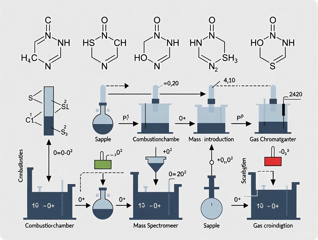
The analytical pathway for CHNOS determination follows a precise sequence from sample introduction to final quantification. The diagram below illustrates this integrated workflow, highlighting the critical transformation points and analytical decision pathways.
Diagram 1: CHNOS Analytical Workflow. This diagram illustrates the complete analytical pathway from sample preparation to final reporting, highlighting critical transformation stages and quality control checkpoints.
Advanced Technical Considerations
Method Optimization for Specific Inorganic Matrices
Analysis of inorganic compounds presents unique challenges that require method customization. Refractory compounds such as metal carbides, nitrides, or sulfides may require modified combustion conditions, including higher temperatures (up to 1,800°C), extended combustion times, or specialized catalysts to ensure complete decomposition [17]. For oxygen determination in metallic systems, the pyrolysis step must be carefully controlled to avoid side reactions that could generate anomalous CO or CO₂. The use of specific catalyst systems can enhance combustion efficiency for challenging matrices; for instance, tungsten-based catalysts effectively lower the combustion temperature required for complete oxidation of ceramic materials [2]. When analyzing volatile inorganic compounds, the sample introduction system may require cooling accessories to prevent premature decomposition. Method development should always include robustness testing to establish optimal conditions for specific sample types, with verification using matrix-matched certified reference materials.
Data Interpretation and Quality Assurance
Accurate interpretation of CHNOS data requires understanding of potential analytical interferences and their mitigation. Common issues include overlapping chromatographic peaks that can lead to incorrect assignment of elements, particularly when sulfur and nitrogen compounds co-elute [2]. Modern instruments address this through advanced separation chemistry and selective detection methods. Quality assurance protocols should include control charts for critical performance parameters such as calibration sensitivity, blank values, and reference material recovery [16]. Data validation should assess combustion completeness through carbon recovery in known standards, with investigation of values outside 98-102% recovery range. For method validation, determine precision (typically <1% RSD for replicates), accuracy (verified with certified materials), and detection limits (generally 0.01-0.05% for most elements) [2] [18]. The use of conservation of mass principles can help identify potential analytical errors, with the sum of elemental percentages providing insight into analysis completeness, though this approach has limitations with complex inorganic matrices containing elements not measured by the technique.
The instrumental anatomy of CHNOS analyzers represents a sophisticated integration of thermal, separation, and detection technologies designed for precise elemental quantification. From high-temperature furnaces ensuring complete sample combustion to advanced detection systems providing specific and sensitive measurement, each component plays a critical role in the analytical workflow [16] [17] [2]. The protocols outlined in this application note provide researchers with comprehensive methodologies for obtaining accurate, reproducible elemental composition data for inorganic compounds. As analytical technology advances, emerging trends including increased automation, miniaturization for field applications, and AI-enhanced data interpretation are poised to further expand the capabilities and applications of CHNOS analysis in inorganic materials research [2] [18]. By understanding both the fundamental principles and practical considerations detailed in this document, researchers can optimize their analytical approaches to address the diverse challenges presented by inorganic compound characterization.
The quantitative determination of carbon (C), hydrogen (H), nitrogen (N), oxygen (O), and sulfur (S) is a cornerstone of analytical chemistry, vital for research in inorganic compounds, materials science, and pharmaceutical development. The journey of CHNOS analysis from empirical Renaissance observations to today's fully automated instrumentation represents a profound evolution in scientific capability. This application note frames this technological progression within a broader thesis on combustion analysis, detailing the historical context, fundamental principles, and detailed protocols that empower modern researchers. The narrative begins with Georgius Agricola, a 16th-century pioneer whose systematic work on minerals and ores laid the conceptual groundwork for the elemental analyzers used in laboratories today [4]. By understanding this historical continuum and the precise methodologies of contemporary analysis, scientists can better appreciate the power and limitations of these essential analytical tools.
Historical Foundations: The Work of Georgius Agricola
Georgius Agricola (1494-1555), born Georg Bauer, was a German physician and scholar whose empirical studies of mining and minerals earned him the posthumous titles "father of mineralogy" and "forefather of geology" [19] [20]. His most influential work, De re metallica (On the Nature of Metals), published in 1556, served as the definitive textbook on mining and metallurgy for two centuries [19] [20].
Agricola's significance to analytical science stems from his revolutionary methodological approach. He rejected the mystical explanations and unquestioning reliance on ancient authorities that characterized much of the science of his time [19] [20]. Instead, he insisted on direct observation and systematic classification, fundamentally shifting the paradigm for investigating the natural world. While practicing medicine in the mining towns of Joachimsthal and Chemnitz, he gained intimate knowledge of ores and mining processes, basing his writings on firsthand observation and information from reliable sources [19] [20].
His critical contributions to the foundation of elemental analysis include:
- Systematic Mineral Classification: In De Natura Fossilium (1546), he developed a classification system for minerals (then called "fossils") based on their physical properties—such as color, weight, transparency, taste, odor, texture, solubility, and combustibility—rather than alphabetical listings or supposed magical traits [19] [20]. This empirical system endured for centuries.
- Theory of Ore Formation: Agricola proposed that mineral veins were formed by subterranean solutions circulating through fissures in rocks, predating modern theories of ore deposition [20].
- Pioneering Combustion Observation: In 1556, Agricola authored the first documented paper on the qualitative observation that different ores, when introduced into a flame, produced changes in "the color of fumes," a foundational principle underlying modern combustion analysis [4].
Table 1: Key Works of Georgius Agricola and Their Contributions
| Work Title | Publication Year | Core Contribution |
|---|---|---|
| Bermannus sive de re metallica dialogus | 1530 | Early dialogue covering mining in Germany and various metal ores [20]. |
| De Ortu et Causis Subterraneorum | 1546 | Theorized on origins of mountains and ore deposits; proposed theory of mineralizing juices [19] [20]. |
| De Natura Fossilium | 1546 | Introduced a new, physical property-based system for classifying minerals [19] [20]. |
| De re metallica | 1556 (Posthumous) | Comprehensive, illustrated encyclopedia of mining, mineralogy, and smelting processes [19] [20]. |
The Principle of Modern CHNOS Elemental Analysis
The core principle of modern CHNOS analysis is the complete, instantaneous combustion of a sample, followed by the separation and quantitative detection of the resulting gaseous products [6] [4]. This process, known as dynamic flash combustion, is a direct, sophisticated descendant of the qualitative observations made by Agricola centuries ago [4].
The analysis is performed to determine the elemental composition, purity, and empirical formula of unknown compounds, providing weight percentages of each element [4]. It is invaluable for characterizing chemicals in natural products, materials science, organic and inorganic synthesis, and pharmaceuticals [4].
Fundamental Workflow
The process can be broken down into four main stages:
- Flash Combustion: A small, weighed sample is combusted in a pure oxygen environment at high temperatures (typically over 1000°C). This "flash combustion" ensures the complete and instantaneous oxidation of the sample, converting its constituents into simple gases [6] [4].
- Gas Reduction and Purification: The resulting mixture of combustion gases is passed over a catalyst, such as copper, which removes excess oxygen and reduces any nitrogen oxides (NO~x~) back to elemental nitrogen (N~2~) [6].
- Gas Separation: The mixture of gases is then separated, most commonly using a gas chromatography (GC) column. This critical step ensures that the gases arrive at the detector at different times, allowing for individual quantification [4].
- Detection and Quantification: The separated gases are detected by specific sensors. The detection methods vary by element [4]:
- Carbon is determined as CO~2~ using a Non-Dispersive Infrared (NDIR) detector.
- Hydrogen is determined as H~2~O, and Nitrogen as N~2~, both typically detected using a Thermal Conductivity Detector (TCD).
- Sulfur is determined as SO~2~, also typically via TCD or NDIR.
- Oxygen is determined separately via pyrolysis (rather than combustion) in a hydrogen-helium gas mixture, converting all oxygen to carbon monoxide (CO), which is then detected [6].
The following diagram illustrates the logical workflow and instrumental components of a modern CHNOS analyzer, integrating the principles of flash combustion, gas chromatography, and detection.
Detailed Experimental Protocols
This section provides a step-by-step methodology for conducting CHNOS analysis, from sample preparation to data interpretation.
Protocol 1: Standard CHNS/O Analysis of a Solid Inorganic Compound
1. Objective: To determine the weight percentages of Carbon, Hydrogen, Nitrogen, Sulfur, and Oxygen in a solid inorganic sample (e.g., a metal-organic framework or mineral carbonate).
2. Principle: The sample is combusted in a high-purity oxygen environment. The combustion products are swept by a helium carrier gas through a reduction oven and separated by a GC column. The concentrations of the separated gases are measured by NDIR and TCD detectors [6] [4].
3. Materials and Reagents:
- CHNOS elemental analyzer (e.g., ELTRA combustion analyzer).
- High-purity oxygen (≥99.995%) and helium (≥99.995%) gases.
- Tin or silver capsules for solid samples.
- Microbalance (capable of 0.001 mg precision).
- Certified calibration standards (e.g., sulfanilamide for CHNS, benzoic acid for O).
- Forceps and sample handling tools.
4. Step-by-Step Procedure:
Step 1: Instrument Preparation and Calibration
- Power on the analyzer and the computer software. Allow the system to stabilize for the time recommended by the manufacturer (typically 1-2 hours).
- Set the combustion and reduction oven temperatures as specified in the instrument manual (e.g., combustion at 1050°C, reduction at 850°C).
- Check and ensure the carrier gas (He) and oxygen gas pressures and flows are within the specified ranges.
- Run at least 3-5 replicates of a certified calibration standard of known composition to create a calibration curve. The software will calculate the calibration factors for each element.
Step 2: Sample Preparation
- Using forceps, place an empty, clean sample capsule onto the microbalance and tare.
- Precisely weigh 1-5 mg of your homogeneous, dry, powdered sample into the capsule. Record the exact mass.
- Fold and crimp the capsule into a compact ball using a capsule press or forceps to prevent sample loss and ensure complete combustion.
Step 3: Sample Analysis
- Load the prepared sample capsule into the autosampler or manually drop it into the sample introduction port.
- Initiate the analysis cycle via the software. The sample will automatically drop into the combustion furnace.
- The analysis cycle, including combustion, gas separation, and detection, is typically completed within 5-10 minutes.
Step 4: Data Acquisition and Calculation
- The instrument software will automatically record the detector signals (chromatograms), integrate the peak areas for each element, and compare them to the established calibration curve.
- The software will then calculate and report the weight percentage of each element in the sample.
5. Data Interpretation:
- The raw output is the mass percentage of C, H, N, S, and O in the sample.
- These values can be used to determine the empirical formula of the compound or to assess its purity by comparing the theoretical and measured compositions.
Protocol 2: Oxygen-Specific Analysis via Pyrolysis
1. Objective: To determine the oxygen content in an inorganic sample where standard combustion is unsuitable.
2. Principle: The sample is pyrolyzed (heated in the absence of oxygen) in a reactor containing hydrogen and helium. Under these conditions, any oxygen in the sample is converted to carbon monoxide (CO). The CO is then separated and quantified, typically by a TCD [6].
3. Procedure Summary:
- The instrument is configured for oxygen mode, requiring a different reactor setup (pyrolysis in H~2~/He).
- Calibration is performed using an oxygen-containing standard like benzoic acid.
- The sample is weighed and introduced into the pyrolysis furnace.
- The resulting CO is carried by the gas stream, separated via GC, and detected. The oxygen content is calculated based on the CO signal [6].
The Scientist's Toolkit: Research Reagent Solutions
Successful and accurate CHNOS analysis relies on a suite of essential materials and reagents. The following table details the key components of the researcher's toolkit.
Table 2: Essential Materials and Reagents for CHNOS Analysis
| Item Name | Function & Importance |
|---|---|
| High-Purity Gases (O₂, He) | Oxygen enables complete sample combustion; Helium acts as an inert carrier gas. Impurities can cause significant analytical errors and high baselines [6]. |
| Certified Calibration Standards | Compounds of known, high-purity elemental composition (e.g., sulfanilamide). Essential for creating the calibration curve to convert instrument signal into quantitative mass percentages [4]. |
| Sample Encapsulation Capsules | Made of ultra-pure tin or silver. These containers hold the sample, aid in combustion via an exothermic "tin flash," and prevent contamination [6]. |
| Catalysts & Reagents | Specific catalysts (e.g., copper for oxygen removal, chromium oxide for combustion) packed in the combustion and reduction tubes. They ensure complete conversion of elements to their target gases and remove interferents [6]. |
| Microbalance | A precision balance capable of weighing to 0.001 mg. Accurate sample weighing is critical, as the results are mass-dependent. A 0.1 mg error in a 2 mg sample introduces a 5% error. |
| Homogenization Tools | Mortar and pestle or a ball mill. Ensures the analyzed sub-sample is representative of the whole, a key factor for obtaining reproducible results, especially for heterogeneous materials. |
Applications in Contemporary Research
CHNOS analyzers are critical across diverse scientific and industrial fields due to their efficiency, minimal sample preparation, and accuracy [4].
Table 3: Applications of CHNOS Analysis in Key Industries
| Industry/Field | Application Examples |
|---|---|
| Pharmaceuticals | Determination of drug compound composition for quality control; verification of synthetic products and raw material purity; refinement of drug formulations [4]. |
| Environmental Science | Evaluation of nutrient content, organic matter, and contamination levels in soil and plant samples; identification and quantification of environmental pollutants [4]. |
| Materials Science & Engineering | Characterization of new materials like nanomaterials, metal-organic frameworks (MOFs), polymers, and advanced ceramics; composition analysis in aerospace and metalworking industries [6] [4] [7]. |
| Agriculture | Nutritional assessment of crops and livestock feed to ensure adequacy of agricultural practices [4]. |
| Energy & Petrochemicals | Analysis of biofuels, solid recovered fuels, and coal for composition and quality control [6] [7]. |
Comparative Data and Limitations
Advantages and Technical Specifications
Modern CHNOS analyzers offer rapid analysis (often under 5 minutes per sample), high sensitivity (capable of detecting element concentrations down to ppm levels), and require only small sample sizes (1-5 mg) without loss of accuracy [6] [7]. They provide a highly effective and versatile solution for routine elemental characterization.
Known Limitations and Complementary Techniques
Despite their power, CHNOS analyzers are not a universal solution. Researchers must be aware of their constraints:
- No Structural Information: The analysis provides only the elemental content (C, H, N, O, S), not the molecular structure, functional groups, or bonding information [6]. Techniques like NMR or IR spectroscopy are required for structural elucidation.
- Sample Form Limitations: While they handle solids, liquids, and viscous substances, samples with high water content can interfere with hydrogen determination and may require drying prior to analysis [6].
- Complex Matrices: For samples containing a wide array of elements beyond CHNOS, techniques like Inductively Coupled Plasma (ICP) spectroscopy or X-ray photoelectron spectroscopy (XPS) may be used alongside or instead of CHNOS analysis for a more comprehensive elemental picture [4].
- Isotopic Information: Standard CHNOS analysis does not provide information on isotope ratios. For this, Isotope Ratio Mass Spectrometry (IRMS) is the preferred method [6].
The path from Georgius Agricola's astute observations of flame and mineral to the automated, precision instruments of the 21st century exemplifies the progress of scientific inquiry. The foundational principle of combustion analysis remains, but its execution has been transformed, allowing today's researchers to obtain precise quantitative data on elemental composition with unprecedented speed and accuracy. By adhering to the detailed protocols and understanding the capabilities and limitations outlined in this application note, scientists and drug development professionals can leverage CHNOS analysis as a powerful tool for characterizing inorganic compounds, ensuring product quality, and driving innovation in their respective fields.
Why Inorganic Compounds? Expanding the Application Beyond Organic Matrices
Combustion analysis, specifically CHNOS elemental analysis, is a powerful analytical technique traditionally associated with characterizing organic compounds. However, a significant paradigm shift is occurring as researchers increasingly recognize its utility for inorganic matrices. This technique, which determines the content of Carbon (C), Hydrogen (H), Nitrogen (N), Oxygen (O), and Sulfur (S) via dynamic flash combustion based on the Dumas method, is now proving indispensable for a wide range of inorganic materials [6]. Modern elemental analyzers completely combust a sample in a high-temperature, oxygen-rich environment, converting the target elements into measurable gaseous compounds (e.g., CO₂, H₂O, N₂, and SO₂), which are then separated and quantified using detectors such as thermal conductivity detectors (TCD) or infrared (IR) detectors [21] [22]. The robustness, precision, and ability to analyze solid and liquid samples without extensive preparation make this method uniquely suited for expanding into inorganic research domains, from metallurgy to advanced material science [21] [23].
Key Applications of CHNOS Analysis in Inorganic Research
The application of CHNOS analysis to inorganic compounds provides critical quantitative data for quality control, material characterization, and research and development. The table below summarizes the primary application areas, specific inorganic matrices analyzed, and the key elements of interest.
Table 1: Key Applications of CHNOS Analysis in Inorganic Research
| Application Area | Specific Inorganic Matrices | Elements Measured | Purpose and Importance |
|---|---|---|---|
| Metallurgy & Alloys | Steels, metal alloys [21] | C, S [21] | Determines critical elements that significantly influence mechanical properties such as ductility, strength, and corrosion resistance [21]. |
| Ceramics & Advanced Materials | Ceramics, minerals, nanomaterials [21] [6] | C, H, N, O, S | Characterizes composition for material development, verifies purity, and analyzes surface contaminants or functionalization. |
| Geological & Environmental Samples | Soils, minerals, rocks [21] | C, N [21] | Assesses soil fertility and health by measuring carbon and nitrogen content, directly related to nutrient cycling [21]. |
| Catalysis Research | Catalysts (e.g., supported metal catalysts) | C, S | Measures coke deposition (carbon) on spent catalysts or determines poison (sulfur) content, informing regeneration processes and performance studies. |
| Inorganic Chemicals & Precursors | Carbonates, inorganic salts [6] | C, H, N, O, S | Verifies chemical composition and purity of starting materials for synthesizing other inorganic compounds or materials. |
Experimental Protocols for Inorganic Matrices
Protocol: Carbon and Sulfur (CS) Analysis in Steel
1. Principle: A weighed sample of steel is combusted in a high-temperature (often >1500°C) furnace in a stream of oxygen. The carbon content is converted to carbon dioxide (CO₂) and the sulfur to sulfur dioxide (SO₂). These gases are then transported by a carrier gas (typically helium) to a detection system [21] [22].
2. Materials and Equipment:
- CHNS/O Elemental Analyzer with high-temperature combustion furnace.
- Tin or silver capsules for sample weighing.
- Microbalance (accuracy ± 0.001 mg).
- Solid standard references for calibration (e.g., certified steel standards with known C and S content).
- Oxygen and Helium gas supplies of high purity.
3. Procedure: a. Calibration: Calibrate the analyzer using certified standard reference materials that closely match the expected composition of the steel samples. b. Sample Preparation: Take a representative sample of the steel, ensuring it is clean and free of surface contaminants. If the sample is chips or a drill, homogenize it. Weigh an appropriate amount (typically 0.5 - 1.0 g for inhomogeneous samples) into a tin capsule [21]. c. Combustion and Analysis: Introduce the encapsulated sample into the combustion reactor via an autosampler. The sample is combusted in a pure oxygen environment. The resulting gases are passed over catalysts (e.g., copper) to remove excess oxygen and convert nitrogen oxides to N₂ [6]. d. Gas Separation and Detection: The gas mixture is passed through specific adsorbent traps to remove impurities. The CO₂ and SO₂ are then separated, typically by gas chromatography, and detected using a thermal conductivity detector (TCD) or infrared (IR) detector [21] [22]. e. Data Calculation: The instrument software calculates the carbon and sulfur concentrations as mass percentages by comparing the detected signal areas of the sample to those from the calibrated standards.
Protocol: Carbon, Hydrogen, and Nitrogen (CHN) Analysis in Soils
1. Principle: The soil sample is combusted in a similar manner to the steel analysis. The combustion converts carbon to CO₂, hydrogen to H₂O, and nitrogen to N₂. The gases are separated and quantified to determine the elemental composition [21].
2. Materials and Equipment:
- CHNS/O Elemental Analyzer.
- Tin capsules.
- Microbalance.
- Soil standard references for calibration.
- Oxygen and Helium gas supplies.
3. Procedure: a. Calibration: Calibrate the instrument with organic standards like atropine or acetamilide, which provide precise CHN ratios, or with certified soil standards. b. Sample Preparation: Air-dry the soil sample and gently grind it to a fine, homogeneous powder, taking care not to over-grind and heat the sample. Weigh a suitable amount (e.g., 50-100 mg for soils with high carbon content) into a tin capsule [21]. c. Combustion and Analysis: The sample is dropped into the combustion tube. Intelligent oxygen dosing ensures complete combustion of the often complex and refractory soil matrix [21]. d. Gas Separation and Detection: The combustion gases are separated using specific chromatography columns. Each gas (CO₂, H₂O, N₂) is measured sequentially by the detector [21]. e. Data Calculation: The software calculates the mass percentages of C, H, and N. The C/N ratio is a key parameter reported for assessing soil fertility and organic matter quality [21].
The Scientist's Toolkit: Essential Research Reagent Solutions
Successful CHNOS analysis in inorganic compounds relies on several key reagents and materials. The following table details these essential components and their functions within the analytical workflow.
Table 2: Essential Research Reagent Solutions for CHNOS Analysis
| Item | Function | Application Notes |
|---|---|---|
| High-Purity Gases (O₂, He) | O₂ is the combustion agent; He is the carrier gas transporting combustion products. | Essential for complete, reproducible combustion and sharp chromatographic separation. Impurities can cause high blanks and inaccurate results. |
| Combustion & Reduction Tubes | Contains catalysts (e.g., copper oxide, tungsten oxide) for complete oxidation and copper for oxygen removal/NOx reduction. | The integrity and activity of the catalysts are critical for quantitative conversion of elements, especially for refractory inorganic samples. |
| Adsorbent Traps & Chemical Scrubbers | Remove interfering combustion products (e.g., halogens, water) from the gas stream. | Protects the separation columns and detectors, ensuring accurate measurement of the target gases. |
| Tin & Silver Capsules | Sample containers for combustion. Silver is often preferred for samples with high halogen content. | Tin aids combustion via an exothermic reaction; the capsule material must not contribute to the elemental signal. |
| Certified Reference Materials (CRMs) | Calibration and validation of the analytical method. | Must be matrix-matched to the samples (e.g., soil CRMs for soil analysis, steel CRMs for metal analysis) for highest accuracy [21]. |
Workflow and Data Analysis Logic
The analytical process for CHNOS in inorganic compounds follows a strict logical pathway from sample preparation to final quantitative reporting. The diagram below illustrates this integrated workflow.
Mastering CHNOS Methods: Step-by-Step Protocols for Inorganic Sample Analysis
Within the framework of combustion analysis for CHNOS (Carbon, Hydrogen, Nitrogen, Oxygen, Sulfur) in inorganic compounds research, proper sample preparation is a critical prerequisite for obtaining accurate and reproducible results. The dynamic flash combustion method at the heart of CHNOS analysis quantitatively converts elements in the sample into measurable gases (CO₂, H₂O, N₂, and SO₂) [6]. The integrity of this process is wholly dependent on the initial sample condition. Inadequate preparation can lead to incomplete combustion, inaccurate quantification, and instrument damage, ultimately compromising research findings in drug development and material science [6] [24]. This document outlines detailed protocols and best practices for handling the diverse sample matrices—solids, liquids, and volatile substances—encountered in inorganic chemistry research.
Sample Preparation Fundamentals for CHNOS Analysis
The core objective of sample preparation for CHNOS analysis is to present a homogeneous, contaminant-free, and accurately weighed specimen that will combust completely and reproducibly. The fundamental principles apply across all sample types:
- Homogeneity: The sample must be uniform to ensure that the small portion weighed (often only a few milligrams) is representative of the entire material [6].
- Purity: Interfering matrices, such as salts, solvents, or moisture, must be removed to prevent skewed results and damage to the analytical system [24].
- Compatibility: The prepared sample must be physically and chemically suitable for introduction into the high-temperature combustion tube.
The following workflow provides a strategic overview of the sample preparation process, guiding the researcher from sample receipt to final analysis.
Sample-Specific Protocols
Solid Samples
Solid samples are the most common matrix for inorganic CHNOS analysis. The primary goals are particle size reduction and thorough drying.
Protocol 1: Grinding and Homogenization of Solid Inorganic Compounds
- Principle: Reduce particle size to increase surface area, ensuring uniform combustion and representative sub-sampling [6].
- Materials: Agate or hardened steel mortar and pestle, mechanical ball mill, analytical balance, spatula, desiccator.
- Procedure:
- Initial Inspection: Visually inspect the solid for obvious heterogeneity or discoloration.
- Coarse Crushing: For large crystals or chunks, use the mortar and pestle to break them down to a coarse powder.
- Fine Grinding: Transfer the coarse powder to a ball mill. Grind for 3-5 minutes in short bursts to avoid heat buildup. Alternatively, continue grinding with the mortar and pestle until a fine, uniform powder is achieved.
- Homogenization: Use a spatula to mix the powder thoroughly, employing a "cone and quarter" technique if necessary.
- Storage: Transfer the homogenized powder to a clean, labeled vial and store in a desiccator.
Protocol 2: Drying and Moisture Removal
- Principle: Remove adsorbed water to prevent overestimation of hydrogen content and avoid sputtering during combustion [6] [25].
- Materials: Oven, vacuum desiccator, moisture-free atmosphere glovebox (for air-sensitive compounds).
- Procedure:
- Oven Drying (for stable compounds): Spread the powdered sample in a thin layer in a glass vial. Place in an oven at 105°C for 4-6 hours (or as determined by prior testing).
- Vacuum Drying (for heat-sensitive compounds): Place the sample in a vacuum desiccator containing a suitable desiccant (e.g., phosphorus pentoxide). Apply vacuum for a minimum of 12 hours.
- Cooling: After drying, allow the sample to cool to room temperature in a desiccator before weighing.
- Verification: The need for drying can be confirmed by Karl Fischer titration on a separate aliquot [6].
Liquid Samples
Liquid samples require careful handling to prevent solvent interference and ensure accurate weighing of the analyte.
Protocol 3: Preparation of Non-Volatile Liquid Solutions
- Principle: Concentrate the analyte or remove volatile solvent matrices that can cause pressure surges in the combustion tube [24].
- Materials: Rotary evaporator, nitrogen evaporator, low-ash filter paper, micro-syringe.
- Procedure:
- Solvent Evaporation: Transfer a known volume of the liquid sample (e.g., 1-10 mL) to a tared evaporation vial. Gently evaporate the solvent to dryness using a rotary evaporator or under a stream of inert nitrogen gas. Avoid boiling or splattering.
- Residue Collection: The solid residue is the analyte for analysis. Follow the protocols for solid samples (grinding, homogenization, drying) if necessary.
- Direct Analysis (for high-boiling liquids): For viscous or non-volatile liquids, use a micro-syringe to directly weigh the sample into a tin or silver capsule. Ensure the capsule is crimped securely to prevent leakage.
Volatile and Highly Viscous Substances
These challenging samples require special techniques to prevent loss before analysis and ensure complete combustion.
Protocol 4: Encapsulation of Volatile and Air-Sensitive Samples
- Principle: Physically contain the sample in a sealed capsule to prevent evaporation and exposure to air [6].
- Materials: Tin or silver capsules, capsule press or crimper, micro-syringe, analytical balance, glovebox (for air-sensitive samples).
- Procedure:
- Capsule Taring: Weigh an empty, dry capsule. Record the mass.
- Sample Introduction (in a fume hood or glovebox):
- For liquids: Use a micro-syringe to introduce the sample directly into the capsule.
- For solids: Quickly transfer the solid powder into the capsule.
- Sealing: Immediately fold and crimp the capsule shut using a capsule press. Apply firm, even pressure to create a hermetic seal.
- Final Weighing: Weigh the sealed capsule to determine the exact mass of the sample by difference. The capsule material itself combusts and does not interfere with the analysis.
Protocol 5: Handling of Highly Viscous Substances
- Principle: Ensure a homogeneous and accurately weighed sample that can be efficiently introduced into the combustion zone.
- Materials: Solvent for dilution (e.g., high-purity acetone, toluene), micro-spatula, capsule.
- Procedure:
- Dilution: Dilute a small amount of the viscous substance with a minimal volume of a compatible, volatile solvent to reduce viscosity.
- Transfer and Evaporation: Transfer a known aliquot of the diluted sample into a capsule. Allow the solvent to evaporate completely at room temperature in a fume hood, leaving the analyte residue behind.
- Encapsulation: Seal the capsule as described in Protocol 4.
Table 1: Summary of Sample Preparation Techniques for Different Matrices
| Sample Matrix | Key Challenges | Recommended Techniques | Primary Goal |
|---|---|---|---|
| Solids | Heterogeneity, adsorbed moisture | Grinding, homogenization, oven/vacuum drying | Homogeneous, dry powder |
| Liquids | Volatile solvent, low analyte concentration | Solvent evaporation, direct encapsulation (for non-volatile) | Solvent-free residue or contained liquid |
| Volatile Substances | Evaporation, air sensitivity | Hermetic encapsulation (Tin/Silver capsules) | Prevent sample loss/degradation |
| Viscous Substances | Inhomogeneity, difficult weighing | Solvent dilution, residue deposition | Homogeneous, manageable aliquot |
The Scientist's Toolkit: Essential Research Reagents and Materials
The following reagents and materials are critical for successful sample preparation in CHNOS analysis.
Table 2: Essential Research Reagents and Materials for Sample Preparation
| Item | Function/Application |
|---|---|
| Tin and Silver Capsules | Sealed containers for volatile, air-sensitive, or liquid samples; prevent premature vaporization [6]. |
| Agate Mortar and Pestle | Grinding and homogenizing solid samples without introducing metallic contaminants. |
| Desiccator | Storage of dried samples to prevent reabsorption of atmospheric moisture [6]. |
| High-Purity Solvents (e.g., Acetone, Toluene) | Diluting viscous samples or cleaning equipment without leaving carbonaceous residues [24]. |
| Micro-syringes (±0.1 µL accuracy) | Precise transfer and weighing of liquid and volatile samples. |
| Low-Ash Filter Paper | Filtration of samples to remove particulate contaminants that could clog the combustion system [24]. |
| Phosphorus Pentoxide (P₂O₅) | Powerful desiccant for creating a moisture-free environment in vacuum desiccators. |
Data Quality and Analytical Considerations
Proper sample preparation directly impacts the quality of the final analytical data. Prepared samples should be analyzed alongside certified reference materials (CRMs) to validate the entire process, from preparation to combustion and detection. The prepared sample must yield elemental results that fall within the accepted deviation for publication, which for many journals is ±0.4% of the calculated value for each element [25]. It is crucial to note that this stringent requirement is itself under scrutiny, as real-world analytical variation can sometimes exceed this limit even for pure compounds [25]. Meticulous preparation is the first and most critical step in ensuring data meets the desired standard. Furthermore, CHNOS analysis provides only elemental composition and does not yield structural information or identify functional groups; techniques like NMR or MS are required for that level of characterization [6] [26] [27].
Combustion analysis for CHNOS (Carbon, Hydrogen, Nitrogen, Oxygen, and Sulfur) is a fundamental analytical technique for determining the elemental composition of inorganic compounds and various other sample types. This method is pivotal in research and drug development for characterizing chemical composition, verifying purity, and identifying unknown substances. The process relies on dynamic flash combustion, based on the Dumas method, to quantitatively convert elements in a sample into measurable gaseous products [6]. Understanding and controlling the core parameters of temperature, oxygen supply, and carrier gas is critical for achieving complete combustion and accurate, reproducible results. These parameters directly influence the efficiency of the combustion reaction, the completeness of the conversion, and the subsequent detection of the elements.
Fundamental Principles and Instrumentation
The Core Combustion Reaction
The CHNOS analysis is an indirect determination method. The sample is combusted at high temperatures in a pure oxygen environment, leading to the complete breakdown of its molecular structure and the conversion of its constituent elements into simple, measurable gases [6] [21]. The primary combustion reactions for carbon, hydrogen, nitrogen, and sulfur can be summarized as follows:
- Carbon (C) is converted to Carbon Dioxide (CO₂)
- Hydrogen (H) is converted to Water (H₂O)
- Nitrogen (N) is converted to Elemental Nitrogen (N₂)
- Sulfur (S) is converted to Sulfur Dioxide (SO₂)
The analysis of Oxygen (O) is performed differently, typically through pyrolysis (high-temperature decomposition in the absence of oxygen) using a hydrogen-helium gas mixture. The oxygen-containing products are then converted to Carbon Monoxide (CO) for detection [6].
Instrumental Workflow: From Sample to Result
The combustion and analysis process follows a precise sequence within an elemental analyzer. The following diagram illustrates the core workflow and the key subsystems involved.
Critical Parameters and Their Optimization
The accuracy of CHNOS analysis is highly dependent on the precise control of several interconnected parameters. The table below summarizes the core parameters, their functions, and their impact on the analysis.
Table 1: Key Combustion Parameters and Their Impact on CHNOS Analysis
| Parameter | Function & Purpose | Typical Conditions & Optimization Notes | Impact on Analysis |
|---|---|---|---|
| Combustion Temperature | Provides activation energy for the complete and instantaneous oxidation of the sample ("flash combustion") [6]. | Varies based on sample matrix; must be high enough to ensure complete decomposition. | Incomplete combustion at low temperatures leads to inaccurate low elemental values. Excessively high temperatures may damage system components. |
| Oxygen Supply | Oxidizing agent that reacts with the sample to form combustion products (CO₂, H₂O, SO₂) and N₂ [6]. | Precisely dosed and intelligently controlled to match the sample type and size for optimal combustion [21]. | Insufficient oxygen causes incomplete combustion. An excess must be managed to avoid interference with gas detection. |
| Carrier Gas | An inert gas (typically Helium, He) that transports the gaseous combustion products through the system [6]. | High-purity helium is standard. Flow rates must be stable and optimized for the instrument configuration. | Ensures sharp peaks and efficient separation of gases in the chromatography column. Contaminants or fluctuating flow cause baseline noise and poor separation. |
| Reaction Environment | Post-combustion, gases pass through a section of copper to remove excess oxygen and reduce nitrogen oxides (NOx) to N₂ [6]. | Copper must be periodically replaced or regenerated as it is consumed in the reaction. | Ensures that nitrogen is measured purely as N₂ and prevents damage to sensitive detectors from oxygen. |
Detailed Experimental Protocol for CHNOS Analysis
Research Reagent Solutions & Essential Materials
Table 2: Essential Materials and Reagents for CHNOS Combustion Analysis
| Item | Function / Specification | Notes for Researchers |
|---|---|---|
| Elemental Analyzer | Instrument with combustion tube, gas chromatography, and detectors (IR, TCD). | Ensure it is calibrated for the specific elements (CHNOS) of interest. |
| High-Purity Gases | Oxygen (O₂): ≥99.995% purity.Helium (He): Carrier gas grade, ≥99.995% purity. | Gas impurities can lead to high blanks and inaccurate results. |
| Combustion Tube Reagents | Copper Oxide (CuO): Ensures complete oxidation.Copper (Cu): Reduces NOx to N₂ and removes excess O₂. | Reagents must be refreshed regularly based on sample throughput. |
| Calibration Standards | Certified micro-analytical standards (e.g., sulfanilamide, atropine). | Must be of known, high purity for accurate calibration curves for each element [4]. |
| Sample Containers | Tin or silver capsules/crucibles. | Choice of material can aid in achieving the high temperature required for flash combustion. |
| Autosampler | Automated sample introduction system. | Typically holds 60-120 samples, enabling high-throughput and reproducible analysis [21]. |
Step-by-Step Methodology
Protocol: Elemental Composition Determination via Flash Combustion
1. Instrument Calibration and Setup:
- Power on the elemental analyzer and the required gas supplies. Set the oxygen and helium flow rates as specified by the instrument manufacturer.
- Allow the system to stabilize, ensuring the combustion and reduction zones have reached their set temperatures (e.g., combustion tube at ~1000-1150°C).
- Calibrate the instrument using certified reference standards that bracket the expected elemental composition of your samples. Run at least three replicates of two different standard concentrations to establish a calibration curve for carbon, hydrogen, nitrogen, and sulfur [4].
2. Sample Preparation:
- For solid samples, homogenize the material into a fine powder.
- Precisely weigh a small amount of sample (typically 1-5 mg) into a tin or silver capsule. The small sample size does not compromise accuracy [6].
- Crimp the capsule tightly to ensure it is sealed and to expel air. For liquid samples, use sealed ampoules or specialized capsules designed for liquids.
3. Sample Introduction and Combustion:
- Load the prepared samples into the autosampler.
- The autosampler will drop the sample capsule into the high-temperature combustion tube in a pure oxygen atmosphere.
- The "flash combustion" occurs instantaneously, completely oxidizing the sample. The tin capsule itself contributes to a highly exothermic reaction, ensuring rapid and complete combustion.
4. Gas Conditioning and Separation:
- The resulting gas mixture (CO₂, H₂O, N₂, SO₂, and excess O₂) is swept by the helium carrier gas through a chamber containing copper.
- The copper removes excess oxygen and reduces any nitrogen oxides (NOx) to elemental nitrogen (N₂) [6].
- The gases then pass through a series of specific absorbent traps to remove any remaining impurities, leaving only CO₂, H₂O, N₂, and SO₂ to be directed to the separation system.
- These gases are separated based on their properties using gas chromatography (GC) columns [6] [21].
5. Detection and Data Analysis:
- The separated gases are detected sequentially. CO₂ and SO₂ are typically detected using non-dispersive infrared (NDIR) detectors, while H₂O and N₂ are detected using a thermal conductivity detector (TCD) [21] [4].
- The instrument software compares the detector signals for the sample to the established calibration curves.
- The content of each element is automatically calculated and reported as a mass percentage (%) of the original sample [6].
Applications in Inorganic Compounds Research
Within the context of inorganic compounds research and drug development, CHNOS combustion analysis serves several critical functions:
- Purity Verification: Confirming the elemental composition of synthesized inorganic compounds or pharmaceutical ingredients against theoretical values, ensuring they meet stringent quality control standards [21] [4].
- Empirical Formula Determination: Establishing the empirical formula of newly synthesized or unknown compounds by providing precise quantitative data on the relative abundance of their constituent elements [4].
- Material Characterization: Analyzing the composition of advanced inorganic materials, such as ceramics, catalysts, and metal-organic frameworks (MOFs), where carbon, hydrogen, and nitrogen content can inform on structure and properties [6] [21].
Limitations and Considerations
Researchers must be aware of the limitations of this technique:
- Structural Information: CHNOS analysis provides only elemental content, not molecular structure or functional group information. It must be supplemented with techniques like NMR or mass spectrometry for full structural elucidation [6].
- Sample Moisture: High water content in samples can interfere with hydrogen determination. Samples may require drying prior to analysis, with moisture content independently checked via Karl Fischer titration if necessary [6].
- Isotopic Information: The standard CHNOS analysis does not provide information on isotope composition, which requires specialized methods like isotope-ratio mass spectrometry (IRMS) [6].
Combustion analysis is a cornerstone technique for determining the elemental composition of inorganic compounds, particularly for quantifying Carbon, Hydrogen, Nitrogen, Oxygen, and Sulfur (CHNOS). The accuracy of this analysis hinges on the effective separation and precise detection of the gaseous combustion products. This application note details the integrated use of Gas Chromatography (GC), Thermal Conductivity Detectors (TCD), and Infrared (IR) detection to characterize inorganic materials. The protocols herein are designed for researchers and scientists in drug development and related fields, providing a framework for reliable and reproducible elemental data essential for material characterization and quality control [16] [4].
Core Analytical Principles and Detector Comparison
The Combustion and Separation Workflow
The analysis begins with the "flash combustion" of a sample at high temperatures (often above 1,000 °C), which instantaneously oxidizes the material. The resulting mixture of gases is then separated by gas chromatography before being directed to specific detectors for quantification [16] [4].
Detection Principles
- Thermal Conductivity Detector (TCD): A universal, non-destructive detector that measures the change in the thermal conductivity of the gas stream flowing over a heated filament. When an analyte elutes from the column, it alters the ability of the gas to carry away heat, causing a measurable change in the filament's electrical resistance. This change is detected using a Wheatstone bridge circuit [28] [29].
- Infrared (IR) Detection: Typically used for carbon detection as CO₂. This method operates on the principle of non-dispersive infrared (NDIR) absorption, where CO₂ molecules absorb infrared radiation at specific wavelengths. The degree of absorption is directly proportional to the concentration of carbon in the sample [4].
- Other Specialized Detectors: While not the focus of this note, other detectors like Flame Ionization (FID) and Electron Capture (ECD) are used for specific applications, particularly in organic analysis [30].
The following workflow illustrates the typical path of a sample from combustion to final elemental quantification.
Detector Performance Specifications
Selecting the appropriate detector is critical for method development. The table below summarizes the key characteristics of detectors relevant to CHNOS analysis.
Table 1: Comparative Performance of Common GC Detectors for Elemental Analysis
| Feature / Detector | TCD | FID | ECD | IR (NDIR) |
|---|---|---|---|---|
| Detection Principle | Measures change in thermal conductivity [28] | Ionizes organic compounds in a H₂/air flame [30] | Captures electrons on electronegative analytes [30] | Measures IR absorption by specific gases (e.g., CO₂) [4] |
| Destructive? | No | Yes | Yes | No |
| Selectivity | Universal | Broad (most organics) | Highly selective (halogens, nitro-compounds) | Selective (CO₂ for carbon) |
| Typical Detection Limits | ~1 ppm (permanent gases) [29] | ~1 pg C/s [29] | ~1 ppt for halogens [29] | Varies, optimized for CO₂ |
| Linear Dynamic Range | 10⁵ – 10⁶ [29] | ~10⁷ [29] | 10⁴ – 10⁵ [29] | Wide |
| Ideal Applications in CHNOS | H₂, N₂, O₂, CH₄, CO, CO₂ (permanent gases) [29] | Not typically used post-combustion | Not typically used post-combustion | Carbon quantification via CO₂ [4] |
Experimental Protocols
Protocol: CHNOS Analysis via Combustion, GC Separation, and TCD/IR Detection
This protocol outlines the procedure for determining Carbon, Hydrogen, Nitrogen, Oxygen, and Sulfur in inorganic compounds.
I. Principle The sample is combusted in a high-temperature furnace under an oxygenated atmosphere, converting the elements into their respective gaseous oxides (CO₂, H₂O, NOₓ, SO₂) and N₂. These gases are separated by a gas chromatography column, and the concentrations of CO₂, H₂O, N₂, and SO₂ are quantified using a combination of IR (for CO₂) and TCD (for H₂O, N₂, and SO₂) detectors. Oxygen is often determined separately using pyrolysis or a modified combustion approach [17] [4].
II. Apparatus and Reagents
- Organic Elemental Analyzer: System equipped with a high-temperature combustion furnace (capable of >1,000°C), a GC separation column, and dedicated IR and TCD detectors [17] [4].
- Microbalance: Capable of weighing to 0.001 mg.
- High-Purity Gases: Helium or argon (carrier gas, ≥99.999%), oxygen (combustion gas, high purity) [31] [29].
- Calibration Standards: Certified reference materials with known CHNOS content, such as sulfanilamide, atropine, or BBOT [4].
- Sample Containers: Tin or silver capsules for solid samples.
III. Procedure Step 1: System Preparation and Calibration
- Ensure the system is leak-free. Pressurize the gas lines and check with an electronic leak detector. Do not use surfactant-based solutions [31].
- Set the combustion furnace temperature according to the manufacturer's specifications for the sample type (e.g., >1,000°C for refractory inorganics).
- Set the GC oven and detector (TCD) temperatures. The TCD block temperature should be stable, typically maintained at 100–150°C to prevent condensation [29].
- Establish gas flows. For a TCD, optimize the carrier gas flow rate, typically within a range of 0.2–1.5 L/min, for stable baseline and peak shape [29].
- Run at least three replicates of a blank (empty capsule) and a series of certified calibration standards to create a calibration curve for each element.
Step 2: Sample Preparation and Weighing
- Accurately weigh a small amount of homogeneous sample (typically 1-5 mg) into a pre-cleaned capsule.
- Fold the capsule tightly to encapsulate the sample, ensuring no material is lost.
Step 3: Sample Analysis
- Load the encapsulated sample into the auto-sampler.
- The sample is automatically dropped into the combustion furnace in a stream of helium carrier gas with a pulse of oxygen.
- "Flash combustion" occurs, quantitatively converting the elements into gases [4].
- The gas mixture is swept through a reduction stage (to convert NOₓ to N₂) and water-removal traps, then into the GC column for separation.
- The separated gases elute and are detected: CO₂ is quantified by the IR detector, and H₂O, N₂, and SO₂ are quantified by the TCD.
Step 4: Data Analysis
- The instrument software integrates the peak areas for each element from the detectors.
- The concentration of each element in the unknown sample is calculated by interpolation from the established calibration curves.
IV. Key Operational Considerations
- Carrier Gas Selection: Helium is preferred for TCD due to its high thermal conductivity, which maximizes sensitivity. However, if analyzing for hydrogen, argon is a better carrier gas to create a larger conductivity difference [29].
- Baseline Stability: Maintain constant inlet pressure and detector temperature to minimize baseline drift and noise. Ensure the laboratory temperature is stable (±5 °C) [31].
- Prevention of Contamination: Use ultra-high-purity gases with inline oxygen and moisture traps to preserve filament life and detector stability [31] [29].
The Scientist's Toolkit: Essential Research Reagents and Materials
The following table lists critical consumables and reagents required for successful CHNOS analysis.
Table 2: Essential Materials for CHNOS Combustion Analysis
| Item | Function | Specification & Notes |
|---|---|---|
| Helium Carrier Gas | Carrier gas for GC separation and TCD operation. | Purity ≥99.999%; essential for low detector noise and high sensitivity [29]. |
| High-Purity Oxygen | Combustion gas for sample oxidation. | Free of hydrocarbons and other contaminants to prevent high blanks. |
| Certified Reference Standards | Instrument calibration and quality control. | e.g., Sulfanilamide, BBOT; must cover the expected concentration range of samples [4]. |
| Tin / Silver Capsules | Sample containers for combustion. | Tin aids combustion exotherm; silver is used for samples containing halogens. |
| Gas Purification Traps | Remove impurities from carrier and combustion gases. | Oxygen and moisture traps are critical for protecting the GC column and TCD filaments [31]. |
| TCD Filaments | Sensing element of the TCD. | Typically made of tungsten-rhenium; can age and require replacement after ~1 year of use [29]. |
Advanced Applications and Technological Developments
The principles of gas separation and detection are continually refined to meet evolving analytical challenges. In combustion analysis for CHNOS, modern elemental analyzers integrate these components into highly automated and robust systems, guaranteeing complete quantitative conversion of the sample for highly precise results [17]. Recent research focuses on enhancing the performance of core components, such as the development of TCDs based on suspended 1D nanoheaters. These advancements aim to achieve ultrafast detection with ultra-low power consumption, paving the way for more portable and efficient analytical instruments in the future [32].
The precise determination of oxygen content in inorganic compounds is a critical analytical challenge in modern research, with significant implications for materials science, catalysis, and drug development. This protocol details a specialized methodology for oxygen analysis through pyrolysis and subsequent carbon monoxide conversion, framed within the broader context of combustion analysis for CHNOS (Carbon, Hydrogen, Nitrogen, Oxygen, Sulfur) determination in inorganic compounds research [17]. The ability to accurately quantify oxygen is essential for characterizing novel materials, understanding catalytic processes, and ensuring the quality and consistency of pharmaceutical compounds.
This application note provides researchers with a comprehensive procedural framework that integrates thermal decomposition techniques with advanced gas analysis. The described approach enables the precise quantification of oxygen content in diverse inorganic matrices, addressing a fundamental need in analytical chemistry. By implementing this protocol, laboratories can establish robust capabilities for elemental characterization that support research and development across multiple scientific disciplines, from fundamental materials research to applied pharmaceutical development [33] [17].
Experimental Principles and Workflows
Fundamental Principles of Pyrolytic Oxygen Analysis
The analytical approach described in this protocol is grounded in the principle of high-temperature combustion followed by specific detection. When a sample undergoes pyrolysis in an oxygen-deficient environment at temperatures exceeding 1000°C, the oxygen present within the sample matrix is converted primarily to carbon monoxide (CO) and, to a lesser extent, carbon dioxide (CO₂) through interactions with carbon [33] [34]. This conversion is facilitated by the proprietary furnace technology in modern elemental analyzers, which guarantees complete quantitative conversion of the sample to measurable gas species—a fundamental prerequisite for highly precise elemental analysis [17].
The Boudouard reaction (CO₂ + C ⇌ 2CO) plays a significant role in this process, particularly in the context of CO₂ conversion during gasification procedures [34]. Research has demonstrated that under optimized conditions, up to 27.2% of CO₂ from a gasification agent can be converted to CO, creating a promising route for the production of renewable carbon sources [34]. This reaction pathway is exploited in the analytical methodology to ensure complete conversion of oxygen-containing species to quantifiable gas products.
Instrumental Configuration
The analytical system required for this protocol consists of several integrated components:
- High-Temperature Combustion Furnace: Capable of maintaining temperatures well above 1000°C to ensure complete sample decomposition [17].
- Gas Regulation System: Patented ball valve technology for blank-free sample transfer, preventing atmospheric contamination during analysis [17].
- Specific Detection System: Thermal conductivity detectors (TCD) or other appropriate detectors for quantifying the generated CO [17].
- Gas Separation Components: Chromatographic columns or other separation mechanisms to isolate CO from other combustion products before detection.
The robustness and longevity of these components are critical for analytical precision, with some manufacturers offering extended guarantees (e.g., 10-year guarantee on high-temperature combustion furnaces and TCD cells) that attest to their reliability for routine analytical operations [17].
Research Reagent Solutions and Essential Materials
Table 1: Key research reagents and materials for oxygen analysis via pyrolysis and CO conversion
| Item | Function | Specifications |
|---|---|---|
| Combustion Analyzer | Quantifies oxygen content via CO detection | CHNOS-capable; furnace >1000°C [17] |
| High-Purity Carrier Gas | Transports pyrolysis products through system | Helium or argon, 99.995% minimum purity |
| Reference Standards | Calibration and method validation | Certified inorganic oxides with known oxygen content |
| Sample Containers | Holds sample during combustion | Tin or silver capsules, clean and pre-weighed |
| Gasification Agents | Creates controlled pyrolysis environment | Oxygen (18.4-23.1 vol%), CO₂ [34] |
| Wood Chips/Carbon Source | Facilitates oxygen conversion to CO | Coniferous wood chips, size category P 45 [34] |
Detailed Methodologies
Sample Preparation Protocol
Proper sample preparation is fundamental to analytical accuracy and precision. The following procedure must be meticulously followed:
- Homogenization: Grind inorganic samples to a fine, consistent particle size (<100 μm) using agate or tungsten carbide equipment to prevent contamination. For powdered samples, ensure thorough mixing to guarantee representative sampling.
- Drying: Dry samples at 105°C for a minimum of 2 hours to remove adsorbed moisture, which would otherwise contribute to the oxygen signal. Store dried samples in a desiccator containing phosphorus pentoxide or another suitable desiccant until analysis.
- Weighing: Accurately weigh 1-3 mg of dried sample into pre-cleaned tin or silver capsules using a calibrated microbalance with 0.001 mg precision. The exact mass should be recorded for subsequent calculations.
- Encapsulation: Fold capsules into compact pellets using capsule closure tools to ensure complete containment of the sample. Avoid contamination from handling by using powder-free gloves throughout the process.
For challenging matrices with high oxygen content or refractory characteristics, preliminary method development with a range of sample masses (1-5 mg) is recommended to establish optimal analytical conditions that ensure complete combustion without exceeding the dynamic range of the detection system.
Instrument Calibration and Validation
Calibration establishes the fundamental relationship between instrumental response and oxygen content, while validation confirms method reliability:
Primary Calibration:
- Select a minimum of three certified reference materials with oxygen content spanning the expected concentration range in samples.
- Analyze each calibration standard in triplicate using the same conditions intended for unknown samples.
- Construct a calibration curve by plotting integrated peak areas against oxygen content (μg or %). The correlation coefficient (R²) should exceed 0.995 for acceptable linearity.
Quality Control:
- Analyze a verification standard with known oxygen content after every 10-12 unknown samples to monitor instrumental drift.
- Establish control limits (±3% relative difference from certified value) for ongoing method validation.
- Implement blank corrections by analyzing empty capsules to account for any background oxygen signal.
System Suitability Tests:
- Before each analytical batch, confirm that the system meets predetermined criteria: baseline stability (<5% fluctuation over 30 seconds), retention time consistency (<2% RSD), and response factor stability (<5% RSD across calibration verification).
Table 2: Representative calibration data for oxygen analysis in inorganic compounds
| Standard | Oxygen Content (%) | Peak Area (μV·s) | Retention Time (min) | RSD (%) |
|---|---|---|---|---|
| Certified Reference A | 15.32 | 154,321 | 3.45 | 1.2 |
| Certified Reference B | 28.45 | 289,654 | 3.42 | 0.8 |
| Certified Reference C | 45.18 | 462,189 | 3.47 | 1.5 |
| Control Standard | 23.16 | 235,487 | 3.44 | 1.1 |
Pyrolysis and CO Conversion Parameters
The pyrolysis and conversion steps require precise control of multiple parameters to ensure complete oxygen conversion and accurate quantification:
Combustion Conditions:
- Set combustion furnace temperature to 1080°C to ensure complete decomposition of inorganic matrices.
- Maintain combustion zone temperature stability within ±5°C throughout the analysis.
- Adjust oxygen injection parameters to achieve a combustion pulse duration of 20-30 seconds, ensuring complete oxidation of the sample.
Reduction and Conversion:
- Maintain reduction furnace at 850°C to efficiently convert CO₂ to CO.
- Use high-purity carbon (e.g., wood chips, charcoal) in the reduction tube to facilitate the Boudouard reaction (CO₂ + C → 2CO) [34].
- Monitor reduction efficiency regularly by analyzing standards with known oxygen content.
Gas Separation and Detection:
- Optimize chromatographic conditions to achieve baseline separation of CO from other combustion products (N₂, CH₄, CO₂).
- Set thermal conductivity detector parameters (filament temperature, bridge current) according to manufacturer specifications for optimal CO detection.
- Use high-purity helium (99.995% minimum) as carrier gas at a flow rate of 120-180 mL/min.
Research indicates that using oxygen-enriched gasification agents (18.4-23.1 vol% O₂) in combination with CO₂ creates a nitrogen-free environment that enhances conversion efficiency and simplifies subsequent gas analysis [34]. This approach can achieve cold gas efficiencies of 83.5-95.5% with only minor formation of interfering tars [34].
Data Analysis and Calculation
The quantitative determination of oxygen content follows a systematic calculation procedure:
Peak Integration: Process chromatographic data using appropriate integration parameters to accurately determine CO peak areas. Apply consistent baseline correction across all analyses.
Concentration Calculation: Calculate oxygen content using the linear regression equation derived from the calibration curve:
- Oxygen (μg) = (Peak Area - Intercept) / Slope
- Oxygen (%) = (Oxygen (μg) / Sample Weight (μg)) × 100
Statistical Reporting: Report results as mean ± standard deviation for replicate analyses (typically n=3). Include relative standard deviation (RSD) as a measure of precision. Apply correction factors based on recovery rates of certified reference materials if necessary.
For samples exhibiting unusual matrix effects or chromatographic interferences, standard addition methodology may be employed to verify accuracy. In this approach, known quantities of oxygen-containing standards are added to the sample, and the increase in response is used to calculate the original oxygen content.
Workflow Visualization
Oxygen Analysis via Pyrolysis and CO Conversion
Results and Data Interpretation
Analytical Performance Metrics
The implementation of this protocol should yield specific performance characteristics that demonstrate method validity:
- Accuracy and Precision: For homogeneous inorganic samples, method accuracy should be within ±2% of certified values for reference materials. Precision, expressed as relative standard deviation (RSD), should be ≤1.5% for replicate analyses of homogeneous materials.
- Detection and Quantification Limits: Calculate method detection limit (MDL) as three times the standard deviation of blank measurements. Under optimal conditions, MDL for oxygen should approach 0.01%. The quantification limit (QL), defined as ten times the standard deviation of blanks, typically reaches 0.03% oxygen.
- Dynamic Range: The method demonstrates linear response across oxygen concentrations ranging from 0.1% to 50%, accommodating diverse inorganic matrices from metal oxides to complex inorganic salts.
Troubleshooting Common Issues
Table 3: Troubleshooting guide for oxygen analysis via pyrolysis and CO conversion
| Problem | Potential Causes | Solutions |
|---|---|---|
| Low/Oxygen Results | Incomplete combustion | Increase combustion temperature; check oxygen supply; reduce sample mass |
| High Blank Values | Contaminated reagents/capsules | Use fresh capsules; analyze system blanks; purify carrier gas |
| Poor Peak Shape | Column degradation; flow issues | Condition/replace separation column; check for leaks; adjust carrier flow |
| Irreproducible Results | Sample heterogeneity; moisture | Improve sample grinding/homogenization; ensure complete drying |
| Declining Sensitivity | Detector aging; catalyst exhaustion | Check detector parameters; replace reduction catalyst |
Data Presentation and Comparison
Table 4: Comparative oxygen analysis data for various inorganic compounds
| Sample Type | Theoretical O (%) | Measured O (%) | Standard Deviation | Recovery (%) |
|---|---|---|---|---|
| Silicon Dioxide (SiO₂) | 53.26 | 52.89 | 0.42 | 99.3 |
| Aluminum Oxide (Al₂O₃) | 47.08 | 46.92 | 0.38 | 99.7 |
| Calcium Carbonate (CaCO₃) | 47.96 | 47.51 | 0.51 | 99.1 |
| Titanium Dioxide (TiO₂) | 39.90 | 39.42 | 0.45 | 98.8 |
| Zinc Oxide (ZnO) | 19.65 | 19.71 | 0.29 | 100.3 |
| Copper Oxide (CuO) | 20.11 | 19.89 | 0.33 | 98.9 |
This application note presents a comprehensive protocol for oxygen analysis in inorganic compounds through pyrolysis and CO conversion, providing researchers with a robust methodology that delivers precise and accurate results. The integration of high-temperature combustion with specific CO detection represents a reliable approach for oxygen quantification across diverse inorganic matrices. The detailed methodologies, instrumental parameters, and troubleshooting guidance contained in this protocol enable laboratories to implement this technique effectively, supporting research initiatives in materials science, catalytic development, and pharmaceutical applications. By adhering to the procedures outlined herein, researchers can generate high-quality oxygen analysis data that meets the rigorous demands of contemporary scientific investigation.
In the realm of pharmaceutical development, the precise determination of a drug substance's elemental composition is a critical pillar of quality control and regulatory compliance. Elemental analysis, particularly the determination of Carbon, Hydrogen, Nitrogen, Oxygen, and Sulfur (CHNOS), provides foundational data for verifying molecular formulas, assessing purity, and ensuring batch-to-batch consistency [35]. This process is indispensable for confirming that active pharmaceutical ingredients (APIs) and excipients meet stringent specifications for identity, strength, and quality. Within the broader context of combustion analysis for CHNOS in inorganic compounds research, these techniques are adeptly applied to characterize catalysts, metal-containing APIs, and various inorganic excipients used in drug formulations.
The regulatory landscape is increasingly rigorous. The United States Pharmacopeia (USP) is implementing modernized standards for impurity testing, effective May 2026, which will replace outdated methods for detecting trace metals and bring U.S. standards in line with those of Europe, Japan, and India [36]. This global harmonization underscores the necessity for robust, precise, and reliable analytical methods like combustion analysis to meet evolving compliance demands. Furthermore, the industry is witnessing a shift towards Quality-by-Design (QbD) principles, where analytical methods are developed with a risk-based approach, and an increased adoption of Real-Time Release Testing (RTRT), which relies on robust process data to ensure quality without end-product testing [37].
The Role of CHNOS Analysis in Pharmaceutical Development
Combustion-based elemental analysis serves as an absolute method for directly measuring the quantities of core elements in a sample, independent of the molecular matrix [35]. This capability is vital for several critical applications in drug development:
- Formula Verification and Purity Assessment: The empirical formula of a new chemical entity must be conclusively verified. Combustion analysis provides the weight percentage of CHNOS elements, allowing for the calculation of the empirical formula and direct comparison to the theoretical composition. Significant deviations can indicate the presence of impurities, solvates, or incorrect synthesis [35] [4]. For instance, a lower-than-expected carbon content might suggest contamination with an inorganic salt.
- Quality Control of Starting and End Products: The purity of raw materials and final drug products is paramount. Quantitative CHNOS analysis is a standard method for certifying that materials meet pre-defined specifications before they enter the manufacturing process [35]. This is crucial for ensuring the safety and efficacy of the final drug product.
- Analysis of Complex Modalities and Inorganic Compounds: As pharmaceutical science advances, drug modalities now include biologics, metal-based therapies, and inorganic compounds used as catalysts or excipients. CHNOS analysis is uniquely capable of characterizing these materials, providing essential data on their elemental makeup that complements other techniques like NMR or MS [38].
A key advantage of modern combustion analysis is its status as an "absolute method" that does not require matrix-specific standards for validation, unlike many spectroscopic techniques [35]. The instrument is typically calibrated using high-purity micro-analytical standards, and the same procedure can be applied to vastly different sample matrices, from organic APIs to inorganic metal complexes [35] [4].
Fundamental Principles of Combustion Analysis for CHNOS
The current state-of-the-art for simultaneous CHNOS analysis is combustion analysis [35]. The fundamental principle involves the complete and instantaneous oxidation of a sample through "flash combustion," which transforms all organic and inorganic substances into simple, measurable gaseous compounds [4].
The general process can be broken down into the following stages:
- Flash Combustion: The sample is combusted in a high-temperature furnace (exceeding 1000°C) within a controlled oxygen environment. This process completely destroys the molecular structure, converting the constituent elements into their gaseous forms [35] [4].
- Carbon (C) is converted to Carbon Dioxide (CO₂)
- Hydrogen (H) is converted to Water (H₂O)
- Nitrogen (N) is converted to elemental Nitrogen (N₂)
- Sulfur (S) is converted to Sulfur Dioxide (SO₂)
- Gas Separation: The resulting mixture of combustion gases is passed through a series of specific traps and chromatography columns. These components separate the gases quantitatively and reversibly, ensuring that each gas can be measured individually without interference [35].
- Gas Detection and Quantification: The separated gases are then detected and quantified by specific detectors [35] [4]:
- Carbon is typically detected via Non-Dispersive Infrared (NDIR) absorption, which measures the infrared radiation absorbed by CO₂.
- Hydrogen and Nitrogen are commonly detected using a Thermal Conductivity Detector (TCD), which senses differences in the thermal conductivity of the gases compared to a reference.
- Sulfur as SO₂ can also be detected by NDIR or other suitable methods.
- Oxygen analysis often requires a separate pyrolysis step (rather than combustion) in an inert atmosphere, converting oxygen to Carbon Monoxide (CO), which is then measured by TCD or an electrochemical sensor.
The signal intensity from these detectors correlates directly with the concentration of each element in the original sample, allowing for the calculation of mass percentages [35].
Workflow Visualization: CHNOS Combustion Analysis
The following diagram illustrates the integrated workflow for the simultaneous determination of CHNS and the separate analysis for oxygen.
Diagram Title: Workflow for CHNS and Oxygen Elemental Analysis
Research Reagent Solutions and Materials
A successful CHNOS analysis relies on high-purity reagents and calibrated materials to ensure accuracy and precision. The following table details the essential components of the "Scientist's Toolkit" for these analyses.
Table 1: Essential Research Reagents and Materials for CHNOS Combustion Analysis
| Item | Function & Importance |
|---|---|
| Micro-analytical Standards | High-purity compounds (e.g., sulfanilamide, aspartic acid) with certified CHNOS content. Used for daily calibration and validation of the elemental analyzer to ensure measurement accuracy [35] [4]. |
| Combustion & Reaction Tubes | Specialized quartz or ceramic tubes housed within the furnace where flash combustion or pyrolysis occurs. They must withstand extreme temperatures and chemical environments [35]. |
| Catalysts | Metal oxide catalysts (e.g., tungsten trioxide, cobaltous oxide) packed within the combustion tube. They ensure the complete oxidation of the sample to simple gases and the quantitative conversion of elements (e.g., S to SO₂) [35]. |
| High-Purity Gases | Helium: The carrier gas for transporting combustion products through the system.Oxygen: For the combustion process.Gas purity is critical to prevent baseline noise and erroneous peaks [35]. |
| Sample Encapsulation Materials | Tin or silver capsules for solid samples. These capsules aid in sample handling and, in the case of tin, contribute exothermically to the "flash combustion" process, ensuring a rapid and complete burn [35]. |
| Desiccants & Chemical Traps | Specific adsorbents (e.g., magnesium perchlorate for water) used to remove unwanted combustion products during the separation process or to purify carrier gases [35]. |
Detailed Experimental Protocols
This section provides a step-by-step protocol for the quantitative determination of CHNOS elements in a drug substance or inorganic compound using combustion analysis.
Protocol 1: Simultaneous Determination of Carbon, Hydrogen, Nitrogen, and Sulfur (CHNS)
Principle: The sample is combusted in a high-temperature oxygen-rich environment. The resulting gases are separated by chromatography and detected, with the element concentrations calculated from the detector signals [35] [4].
Materials and Equipment:
- Elemental Analyzer equipped with autosampler, combustion tube, gas chromatography column, and detectors (NDIR for C and S, TCD for H and N).
- Microbalance (capable of weighing to ±0.001 mg).
- High-purity oxygen and helium gases.
- Tin capsules and forceps.
- Certified CHNS standard (e.g., sulfanilamide).
Procedure:
- System Preparation: Power on the instrument and ensure the combustion furnace is at operating temperature (typically >1000°C). Set the helium and oxygen gas flows to the manufacturer's specifications. Allow the system to stabilize until a stable baseline is achieved on the detectors.
- Calibration: Weigh 2-3 mg of the certified standard into a tin capsule. Crimp the capsule closed to exclude air. Place it in the autosampler. Run a minimum of 3-5 replicates to establish a calibration factor for each element.
- Sample Preparation: Accurately weigh 2-5 mg of the homogeneous, dry drug substance into a tin capsule. The sample weight should be within the linear range of the calibration. Crimp the capsule closed, ensuring no sample is lost.
- Combustion and Analysis:
- Load the sample capsule into the autosampler.
- The autosampler drops the capsule into the combustion tube, where it is flash-combusted in a pulse of oxygen.
- The resulting gases (CO₂, H₂O, N₂, SO₂) are swept by the helium carrier gas through a mixing chamber and then into a gas chromatography (GC) column.
- Gas Separation and Detection: The GC column separates the gases based on their affinity for the stationary phase. They elute from the column as distinct, sharp peaks and pass through the detectors sequentially.
- CO₂ and SO₂ are measured by NDIR detectors.
- H₂O and N₂ are measured by the TCD.
- Data Evaluation: The instrument software integrates the peak areas for each element. The concentration of each element in the sample is calculated by comparing the sample peak areas to the calibration curve established from the standards. Results are typically reported as mass percentages (%C, %H, %N, %S).
Protocol 2: Determination of Oxygen
Principle: The sample is pyrolyzed at high temperature in an inert helium atmosphere. The oxygen in the sample is quantitatively converted to carbon monoxide (CO), which is then measured by a thermal conductivity detector [35].
Materials and Equipment:
- Elemental Analyzer with a pyrolysis furnace and oxygen-specific setup.
- Microbalance.
- High-purity helium gas.
- Silver capsules and forceps.
- Certified oxygen standard (e.g., benzoic acid).
Procedure:
- System Preparation: Power on the pyrolysis furnace and set to the required temperature (typically ~1100-1300°C). Purge the system with high-purity helium.
- Calibration: Weigh 2-3 mg of the oxygen standard into a silver capsule. Analyze in replicates to establish the calibration factor for oxygen.
- Sample Preparation: Accurately weigh 2-5 mg of the sample into a silver capsule and crimp it closed.
- Pyrolysis and Analysis: The sample capsule is dropped into the hot pyrolysis tube filled with an inert carbon source (e.g., platinum-coated carbon). Under these conditions, oxygen in the sample is converted to CO.
- Gas Detection: The resulting CO gas is carried by helium through chemical traps to remove interfering species (like halogens and sulfur oxides) and into the TCD for quantification.
- Data Evaluation: The software calculates the oxygen content based on the CO peak area and the pre-determined calibration factor. The result is reported as mass percentage (%O).
Data Interpretation and Method Validation
Calculation of Empirical Formula: The mass percentages obtained from CHNOS analysis are used to determine the empirical formula. This is done by:
- Converting the mass of each element to moles.
- Dividing each mole value by the smallest mole number obtained.
- Rounding to the nearest whole number to establish the atom ratios.
Method Validation Parameters: For regulatory compliance, the analytical method must be validated. Key parameters, as guided by ICH Q2(R2), include [37]:
- Accuracy: Determined by spiking studies or analysis of certified standards, with recovery typically required to be 98-102%.
- Precision: Measured as repeatability (multiple injections of the same sample) and intermediate precision (different days, different analysts), with RSD typically <1%.
- Linearity and Range: Demonstrated by analyzing standards across a range of concentrations (e.g., 1-5 mg).
- Robustness: The ability of the method to remain unaffected by small, deliberate variations in method parameters (e.g., combustion temperature, gas flow rate).
Table 2: Typical Method Validation Criteria for CHNOS Analysis in Pharmaceuticals
| Validation Parameter | Acceptance Criteria | Experimental Approach |
|---|---|---|
| Accuracy | Recovery 98-102% | Analysis of certified reference material (CRM) |
| Precision (Repeatability) | RSD < 1.0% for C, H, N, O, S | Six replicate analyses of a homogeneous sample |
| Linearity | R² > 0.999 | Analysis of 5-7 standard weights across the working range |
| Range | 0.5 mg to 5 mg sample weight | Established from linearity studies |
| Robustness | %RSD < 1.0% for all elements | Deliberate variation of O₂ time, furnace temperature |
Combustion analysis for CHNOS elements remains a cornerstone technique in modern drug development. Its robustness, precision, and status as an absolute method make it indispensable for the critical tasks of drug purity assessment and formula verification [35]. As the pharmaceutical industry advances with increasingly complex modalities like biologics and metal-based therapies, and as global regulatory standards become more stringent, the role of precise elemental analysis will only grow in importance [36] [38].
The successful implementation of these methods, framed within a QbD and lifecycle management approach, ensures that drug products are developed and manufactured with an inherent assurance of quality, safety, and efficacy from the research bench to the commercial market [37]. By providing unambiguous data on the fundamental building blocks of matter, CHNOS combustion analysis continues to be a vital tool in the scientist's arsenal for safeguarding public health.
Solving CHNOS Challenges: Troubleshooting and Optimization for Reliable Results
Managing Sample Heterogeneity and High Water Content
Elemental analysis for Carbon, Hydrogen, Nitrogen, Oxygen, and Sulfur (CHNOS) via combustion is a fundamental technique in analytical chemistry, providing critical data for characterizing organic and inorganic compounds [21]. However, two significant challenges frequently compromise data accuracy: sample heterogeneity and high water content. Inorganic compounds research presents unique difficulties due to varied material structures and compositions that can resist uniform combustion [39]. Simultaneously, water content artificially inflates hydrogen measurements and impacts combustion dynamics [6]. This application note details standardized protocols for managing these challenges, ensuring reliable CHNOS data for research and drug development applications. The guidance is framed within a broader thesis on advancing combustion analysis methodologies for complex inorganic matrices.
Core Challenges in CHNOS Analysis
Sample Heterogeneity
Sample heterogeneity refers to the non-uniform distribution of components within a material. This is a common characteristic of coal, biomass, soils, and engineered inorganic composites [16] [39]. In combustion analysis, heterogeneity can cause sub-sampling error, where a small analyzed portion is not representative of the bulk material. This leads to imprecise and non-reproducible elemental composition data. The problem is exacerbated in materials with complex internal structures, such as the porous "coal frame" found in coal-water fuels [39].
High Water Content
Water content directly interferes with the quantitative determination of hydrogen, as the combustion process cannot distinguish between hydrogen from the sample matrix and hydrogen from water [6]. Furthermore, the evaporation of water during the combustion process requires significant energy, which can lower the combustion temperature and lead to incomplete combustion of the sample [40]. This is particularly critical for samples like plant materials or coal-water slurries, where achieving sustained ignition requires careful thermal management [39] [40].
Experimental Protocols
Protocol for Homogenizing Heterogeneous Solids
This protocol is designed for heterogeneous solid samples such as coal, biomass, soils, and inorganic composites.
- Principle: Reduce particle size and mix thoroughly to ensure any aliquot taken for analysis is representative of the whole sample.
- Materials: Jaw crusher, mechanical mill (e.g., ball mill), mortar and pestle, sieve set (e.g., 100 µm), sample splitter (riffle splitter), laboratory balance.
- Procedure:
- Primary Crushing: For large, coarse samples (e.g., coal, rocks), use a jaw crusher to reduce the material to a gravel-sized fraction (~5 mm).
- Secondary Milling: Transfer the crushed material to a mechanical mill (e.g., a ball mill) for fine grinding. The duration of milling depends on the material's hardness and the desired fineness.
- Sieving: Pass the milled material through a sieve (e.g., 100 µm) to obtain a consistent particle size fraction. Material that does not pass through should be returned to the mill for further grinding.
- Mixing and Splitting: Use a sample splitter (riffle splitter) to homogenize and reduce the sample quantity. Repeat the splitting process until a representative analytical sample of 10-100 mg is obtained.
- Verification: To verify homogeneity, analyze multiple aliquots from the same prepared sample. The relative standard deviation (RSD) of the carbon content should be <2%.
Protocol for Managing High Water Content
This protocol outlines steps to account for or remove water that would otherwise interfere with hydrogen determination.
- Principle: Either measure the water content separately to correct the final hydrogen value, or remove the water prior to analysis without volatilizing organic hydrogen.
- Materials: Laboratory oven, desiccator, Karl Fischer titrator, moisture analyzer, helium-purged glove bag, tin capsules for solid samples.
- Procedure A (Drying and Correction):
- Determine Water Content: Weigh a separate aliquot of the wet sample (approx. 1 g). Analyze its water content using a validated method, preferably Karl Fischer titration, for accurate results [6].
- Dry the Analytical Sample: Weigh the precise amount of the wet sample into the combustion capsule. Dry the capsule in a laboratory oven at a temperature that removes free water without degrading the sample (e.g., 105°C for 2-4 hours). The optimal temperature and duration must be determined empirically for each sample type.
- Cool and Analyze: Cool the dried sample in a desiccator and re-weigh to determine the dry mass. Proceed with CHNOS analysis.
- Data Correction: Correct the final measured hydrogen percentage using the formula:
- H~dry~ = (H~measured~ × Mass~dry~) / (Mass~wet~ × (1 - %Water/100)) where H~dry~ is the corrected hydrogen content of the dry sample, and H~measured~ is the value obtained from the analyzer.
- Procedure B (Handling Hygroscopic Samples):
- For samples that readily absorb atmospheric moisture, all preparation must be performed in a controlled, dry environment.
- Weigh samples quickly inside a helium-purged glove bag or under a stream of inert gas.
- Seal samples in airtight tin capsules immediately after weighing to prevent moisture uptake before combustion.
Data Presentation and Analysis
The following tables summarize key quantitative data and experimental parameters relevant to managing the discussed challenges.
Table 1: Impact of Heterogeneity and Moisture on Combustion Characteristics
| Sample Type | Typical Moisture Content (wt.%) | Minimum Sustained Ignition Temperature | Key Homogenization Challenge |
|---|---|---|---|
| Coal-Water Fuel [39] | Up to 60% | ~600 °C | Porous coal frame structure |
| Plant Biomass [21] | Variable, can be high | Not Specified | Fibrous and cellular structure |
| Human Faeces [40] | Up to 60% | ~600 °C | Organic and inorganic particulate mix |
| Pharmaceutical Blend | Low, but hygroscopic | Not Specified | Uniform mixing of API and excipients |
Table 2: Essential Research Reagent Solutions and Materials
| Item | Function/Description |
|---|---|
| Leco CHNS Analyzer [16] | Instrument for rapid, simultaneous determination of C, H, N, S via flash combustion. |
| Helium Carrier Gas [6] | Inert gas used to transport combustion products through the separation and detection system. |
| High-Purity Oxygen [21] | Oxidant for the complete flash combustion of the sample in the furnace. |
| Tin Capsules [21] | Sample containers that aid in rapid, high-temperature combustion. |
| Copper Oxide (CuO) [41] | A traditional combustion catalyst used to ensure complete oxidation of carbon to CO₂. |
| Copper Metal [6] | Placed in the reduction tube to remove excess oxygen and convert nitrogen oxides to N₂. |
| Karl Fischer Reagents [6] | Used in the volumetric or coulometric titration to determine water content precisely. |
Workflow and Pathway Visualization
The following diagram illustrates the integrated workflow for managing heterogeneous and wet samples, from preparation to data correction.
Sample Preparation and Analysis Workflow
Robust CHNOS analysis of complex inorganic compounds hinges on effectively addressing sample heterogeneity and water content. The protocols outlined herein—emphasizing rigorous mechanical homogenization, strategic drying, and precise moisture correction—provide a reliable framework for obtaining accurate elemental data. For researchers in drug development and materials science, adherence to these methods ensures data integrity, supports quality control, and facilitates valid comparisons across studies. Mastery of these sample preparation techniques is therefore not merely procedural but foundational to generating meaningful scientific insights from combustion-based elemental analysis.
Combating Contamination and Incomplete Combustion
Within the precise field of elemental analysis for inorganic compounds, the accuracy of CHNOS (Carbon, Hydrogen, Nitrogen, Oxygen, Sulfur) determination is paramount. Combustion analysis, the foundational technique for this quantification, is highly sensitive to methodological integrity. Incomplete combustion and sample contamination represent two critical challenges that can systematically compromise data quality, leading to erroneous compositional results and flawed scientific conclusions. This document outlines detailed application notes and protocols designed to help researchers identify, prevent, and mitigate these issues, thereby ensuring the reliability of analytical results within a broader research context.
Understanding the Fundamentals
The Combustion Process in CHNOS Analysis
In CHNOS analysis, a sample is combusted in a high-temperature furnace (often exceeding 900°C) within a controlled, oxygen-rich environment [2]. This process breaks down the material, converting its constituent elements into measurable gaseous forms:
- Carbon is converted to Carbon Dioxide (CO₂).
- Hydrogen is converted to Water (H₂O).
- Nitrogen is converted to Nitrogen oxides (NOₓ) or Nitrogen gas (N₂).
- Sulfur is converted to Sulfur Dioxide (SO₂).
- Oxygen is typically determined indirectly via pyrolysis, converting it to Carbon Monoxide (CO) and CO₂ [2].
These resultant gases are then separated (e.g., via gas chromatography) and detected using methods such as Thermal Conductivity Detectors (TCDs) or Infrared Detectors (IR) [2].
The Critical Problem: Incomplete Combustion
Incomplete combustion occurs when the burning process is suboptimal, preventing the complete conversion of elements into their target gases [42]. In oil and gas operations, this is often caused by variable gas flows, equipment degradation, or adverse environmental factors [42]. In a laboratory setting, common causes include:
- Insufficient furnace temperature.
- Inadequate oxygen supply or poor carrier gas flow dynamics.
- Sample size too large for complete combustion.
- The presence of refractory compounds that resist oxidation.
- Contaminants that poison catalysts.
This incomplete process can generate soot (black carbon), carbon monoxide (CO), unburned methane, and volatile organic compounds (VOCs) [42] [43]. For analytical results, this translates into low recoveries for carbon, hydrogen, and sulfur, and a cascade of data inaccuracies.
The Pervasive Challenge: Sample Contamination
Contamination introduces extraneous elements that are mistakenly quantified as part of the sample. This can occur from:
- Impure reagents or gases.
- Improperly cleaned sampling tools or containers.
- Carryover from previous samples.
- Environmental exposure to laboratory air, dust, or skin oils.
Contamination leads to positively biased results, falsely elevating the measured percentage of the contaminant element.
Experimental Protocols for Mitigation
The following protocols are designed to be integrated into standard CHNOS analytical procedures to enhance data fidelity.
Protocol 1: Verification of Combustion Completeness
Principle: This protocol assesses combustion efficiency by analyzing a standard with known elemental composition and monitoring for by-products of incomplete combustion.
Materials:
- Elemental Analyzer
- Certified Reference Material (CRM) similar to sample matrix (e.g., EDTA, BBOT)
- High-purity oxygen and carrier gases
- Combustion tubes and catalysts
Methodology:
- System Calibration: Calibrate the analyzer using an appropriate CRM as per manufacturer guidelines.
- Control Analysis: Run the CRM and record the measured values for C, H, N, O, S.
- By-Product Monitoring:
- Visually inspect the combustion tube for soot deposits after analysis [43].
- Analyze the CRM and observe the chromatogram for anomalous peaks (e.g., a large CO peak can indicate incomplete combustion in carbon/helium mode).
- Data Interpretation:
- Combustion Efficiency Check: Compare the measured values of the CRM to the certified values. Recovery rates consistently below 98-99% may indicate incomplete combustion.
- Soot Inspection: The presence of soot is a definitive visual indicator of incomplete combustion and requires immediate corrective action [43].
Protocol 2: Assessment and Control of Sample Contamination
Principle: This protocol establishes a baseline for procedural blanks and implements rigorous cleaning procedures to identify and minimize contamination sources.
Materials:
- High-purity solvents (e.g., acetone, methanol)
- Contamination-free sample vials and capsules
- Clean forceps and tools
- Ultrasonic cleaning bath
Methodology:
- Tool Cleaning: Clean all tools and vials with high-purity solvents using an ultrasonic bath. Perform this cleaning in a dedicated, dust-free environment.
- Procedural Blank Determination:
- Weigh an empty, cleaned sample capsule into the analyzer.
- Run the blank analysis using the same method as for actual samples.
- Repeat this process 3-5 times to establish a consistent baseline value for the blank.
- Blank Subtraction and Acceptance Criteria:
- The average blank value for each element should be subtracted from sample results if statistically significant.
- Establish a maximum acceptable blank level (e.g., blank signal < 1% of the typical sample signal). If blanks exceed this level, the source of contamination must be investigated and eliminated before sample analysis.
Data Presentation and Analysis
Table 1: Diagnostic Indicators and Corrective Actions for Combustion Issues
| Observed Symptom | Potential Cause | Corrective Action |
|---|---|---|
| Low recovery for C, H, S; visible soot in tube [43] | Incomplete combustion | Increase furnace temperature; check oxygen supply/pressure; reduce sample mass; inspect/replace combustion catalyst. |
| High & variable blank for C | Contaminated solvents or sample cups | Use higher purity solvents; implement rigorous cup cleaning protocol; analyze blanks more frequently. |
| Erratic N values | Air leak in system; contaminated helium carrier gas | Check system seals and connections; use higher purity helium with proper gas filters. |
| Poor O recovery | Incomplete pyrolysis; contaminated reactor | Service/clean the pyrolysis reactor; ensure proper reactor temperature. |
Table 2: Essential Research Reagent Solutions and Materials
| Item | Function / Explanation |
|---|---|
| Certified Reference Materials (CRMs) | High-purity standards with certified elemental composition; used for instrument calibration and validation of analytical method accuracy and precision. |
| High-Purity Oxygen (≥99.995%) | The combustion gas; impurities can lead to incomplete combustion or high analytical blanks. |
| Ultra-High Purity Helium Carrier Gas | Carries the product gases through the separation columns and detectors; impurities can cause high baselines and noise. |
| Combustion & Reduction Catalysts | Packed in the analyzer's furnaces to ensure complete oxidation of carbon and hydrogen, and reduction of nitrogen oxides to N₂. |
| Tin or Silver Sample Capsules | Used to encapsulate samples; they aid in the combustion process via an exothermic reaction and trap certain contaminants (e.g., halogens). |
| Contamination-Free Solvents | High-purity acetone or methanol for effective cleaning of labware and tools to prevent sample contamination. |
Workflow Visualization
The following diagram outlines a systematic workflow for diagnosing and addressing issues of contamination and incomplete combustion in the analytical process.
Combating contamination and incomplete combustion is not a single action but a continuous practice of rigorous methodology and vigilant quality control. By integrating the protocols and diagnostic checks outlined in this document—systematic blank assessment, CRM validation, and visual inspection—researchers can significantly enhance the integrity of their CHNOS data. A robust, validated analytical process is the foundation upon which reliable research in inorganic chemistry and drug development is built, ensuring that conclusions are drawn from accurate and trustworthy elemental composition data.
Within the framework of combustion analysis for CHNOS (Carbon, Hydrogen, Nitrogen, Oxygen, Sulfur) in inorganic compounds research, the long-term reliability of analytical instruments is a cornerstone of data integrity. The furnace and detector are the core components of a combustion elemental analyzer, and their performance directly dictates the accuracy and precision of elemental quantification [2]. This document provides detailed application notes and protocols designed to help researchers, scientists, and drug development professionals maintain these critical subsystems, thereby ensuring consistent, high-quality analytical results for inorganic materials research.
Maintenance Schedules and Key Components
Proactive maintenance is essential to prevent instrument drift, calibration failures, and unexpected downtime. The following table summarizes the core components and recommended maintenance frequencies for a CHNOS analyzer's combustion and detection system.
Table 1: Maintenance Schedule for Furnace and Detector Systems
| Component | Key Maintenance Activities | Frequency | Purpose & Notes |
|---|---|---|---|
| Combustion Tube | Inspect for cracks, erosion, or catalyst depletion; Replace when necessary [44]. | Every 200 samples or as needed [44]. | Ensures complete combustion. Tubes are packed with reagents like copper oxide and electrolytic copper [44]. |
| Reduction Tube | Inspect and replace packing reagents [44]. | As needed, based on sample load. | Removes excess oxygen and reduces nitrogen oxides to N₂ [21]. |
| Gas Purification | Replace traps for moisture and other impurities. | Regularly, per manufacturer's advice. | Maintains purity of carrier and combustion gases, critical for baseline stability. |
| Detector (TCD/IR) | Perform system checks for leaks and sensitivity; Verify calibration with standards [44]. | Start of each run/sequence [44]. | Ensures accurate quantification of gaseous combustion products [2]. |
| Autosampler | Clean and inspect for wear. | Weekly/Monthly | Prevents cross-contamination and ensures accurate sample delivery. |
| O-Rings & Seals | Inspect and replace. | As needed, during tube changes. | Maintains a sealed, airtight system to prevent atmospheric contamination. |
Detailed Maintenance Protocols
Combustion Tube Replacement and Packing
The combustion tube is subjected to extreme temperatures and corrosive gases, making its integrity paramount.
Experimental Protocol: Combustion Tube Replacement
- Power Down and Isolate: Allow the instrument to cool completely. Shut off the power and isolate the carrier and oxygen gas supplies.
- Disassemble Furnace Assembly: Carefully remove the furnace housing and disconnect the combustion tube from its fittings.
- Remove Old Tube: Gently extract the worn combustion tube. Inspect it for any visible damage, such as cracks or significant erosion.
- Pack New Tube (if applicable): If packing a tube in-house, use the specified reagents. For a CHNS tube, this typically involves packing with copper oxide wires and electrolytic copper [44]. For an oxygen pyrolysis tube, use nickel-plated carbon and quartz turning [44].
- Install and Reconnect: Carefully place the new (or repacked) tube into the furnace. Reconnect all gas lines and electrical connections according to the manufacturer's diagram.
- Leak Check: Once reassembled, pressurize the system with helium and perform a comprehensive leak check using an appropriate leak detector or soap solution before proceeding [44].
Detector Performance Verification and Calibration
The Thermal Conductivity Detector (TCD) must be stable and sensitive for accurate quantification.
Experimental Protocol: Daily QC and Detector Check
- System Conditioning: Run an unweighed standard (e.g., BBOT) in a "bypass" cycle to condition the system [44].
- Blank Run: Analyze an empty tin capsule to establish blank values and ensure no contamination remains in the system [44].
- Calibration Curve Generation: Weigh 2-3 mg of a certified standard (e.g., BBOT or Acetanilide) in triplicate and run them as "standards" to generate a fresh calibration curve [45] [44].
- Quality Control Check: Run one or two additional weighed standards as "unknowns" (checks). The measured values for these checks should be within 0.3% of the theoretical mass percentage to verify the calibration's accuracy [2] [44].
- Chromatogram Inspection: Visually inspect the chromatograms for sharp, well-resolved peaks. The vertical red lines representing the integration window can be adjusted in the software's component table to ensure accurate peak area calculation [44].
The Scientist's Toolkit: Essential Research Reagents and Materials
The following materials are critical for the operation and maintenance of a CHNOS combustion analyzer.
Table 2: Essential Research Reagents and Consumables
| Item | Function | Application Note |
|---|---|---|
| Pressed Tin Capsules | Sample container for most solid samples [44]. | Promotes complete combustion through an exothermic reaction (tin fire) [21]. |
| Silver Capsules | Sample container for halogenated samples and O analysis [44]. | Prevents aggressive combustion that could damage the quartz tube for volatile samples. |
| Calibration Standards (e.g., BBOT, Acetanilide) | Used to generate the calibration curve for quantifying elements [44]. | Must be pure, dry, and of known composition. BBOT is suitable for CHNS as it contains all four elements [44]. |
| Vanadium Pentoxide | Combustion aid [44]. | Especially useful for samples requiring accurate sulfur determination, ensures complete oxidation. |
| Copper Oxide Wires & Electrolytic Copper | Reagents for packing the CHNS combustion/reduction tube [44]. | Copper oxide aids combustion, while elemental copper removes excess oxygen and reduces NOx to N₂ [21] [44]. |
| Nickel-plated Carbon | Reagent for packing the oxygen pyrolysis tube [44]. | Catalyzes the conversion of oxygen-containing products to carbon monoxide (CO) for detection [21]. |
| UHP Helium & Oxygen | Carrier gas and combustion gas, respectively [44]. | Ultra High Purity (UHP) gases are essential to prevent contamination and baseline noise. |
Workflow and System Logic
The long-term performance of the furnace and detector is governed by a logical sequence of preventative maintenance, quality control, and troubleshooting. The following diagram visualizes this workflow, connecting routine tasks to the specific performance outcomes they safeguard.
Calibration Strategies with High-Purity Micro-Analytical Standards
In the realm of combustion analysis for CHNOS (Carbon, Hydrogen, Nitrogen, Oxygen, Sulfur) in inorganic compounds research, the precision and accuracy of quantitative results are fundamentally dependent on robust calibration strategies employing high-purity micro-analytical standards. Elemental analysis via combustion is a well-established technique where a sample is combusted at high temperatures in an oxygen environment, converting elements into measurable gases like CO₂, H₂O, N₂, and SO₂ [6] [4]. The detection of these gases is typically achieved through methods such as thermal conductivity detection (TCD) or non-dispersive infrared (NDIR) detection [4] [46]. However, the correlation between detector response and elemental concentration is not absolute, necessitating meticulous calibration using certified reference materials to establish accurate quantitative relationships. This document outlines detailed protocols and application notes for effective calibration, framed within the rigorous demands of inorganic compounds research.
The Critical Role of High-Purity Standards
High-purity micro-analytical standards are the cornerstone of reliable quantitative elemental analysis. The use of "micro-analytical standard" compounds is essential for the accurate quantification of elements [4]. Their function extends beyond simple instrument calibration to encompass method validation and quality assurance.
- Foundation of Accuracy: Impure standards introduce systematic errors that compromise the entire analytical process. As highlighted in metabolomic studies, even minor impurities can cause overlapping signals or misleading data, fundamentally undermining the reliability of results [47]. In the context of CHNOS analysis, an impurity in a carbon standard could lead to an overestimation of carbon content in an unknown inorganic sample.
- Purity Requirements: The calibration process requires standards of sufficient purity to be competitively available from multiple suppliers, often referred to as ACS reagent grade [25]. The standards must be meticulously characterized, with purity exceeding 99% being a common benchmark to ensure analytical reliability [47]. This is particularly crucial for inorganic compounds, which may have complex matrices.
- Traceability and Certification: Reputable standard providers supply a Certificate of Analysis (CoA) that documents critical quality assurance data, including chromatographic purity testing and structural identity confirmation via techniques like NMR [48] [47]. This traceability is non-negotiable for regulatory compliance and for defending the validity of research findings in scientific publications.
Calibration Methodologies
A comprehensive calibration strategy involves multiple stages, from standard selection to the establishment of the calibration curve itself.
Selection of Calibration Standards
Choosing the appropriate standards is the first critical step. The selection must be fit-for-purpose, considering the sample matrix and the elements of interest.
Table 1: Types of High-Purity Micro-Analytical Standards for Calibration
| Standard Type | Description | Primary Function | Considerations |
|---|---|---|---|
| Pure Element Compounds | High-purity, simple compounds (e.g., sulfanilamide for CHNS). | Fundamental calibration for element response. | Must be stable, non-hygroscopic, and have a defined composition [49]. |
| Matrix-Matched Standards | Standards with a chemical background similar to the sample. | Correct for matrix-specific combustion effects. | Ideal but often difficult to obtain for novel inorganic materials. |
| Custom Blends | Mixtures prepared to user specifications [48]. | Simulate complex or specific sample compositions. | Essential for method development of unique inorganic compounds. |
The Calibration Workflow
The calibration process is a multi-step procedure that ensures the instrument produces accurate and reproducible results. The following workflow diagram outlines the key stages from preparation to validation.
Quantitative Calibration and K-Factor Determination
The core of quantitative analysis lies in establishing a relationship between the detector signal and the mass of the element. This is commonly achieved through the calculation of a K-factor (calibration coefficient) [49].
The general formula for calculating the mass percentage of an element in a sample is:
Element % = (Signalsample - Signalblank) × K-factor / Sample Weight × 100%
The K-factor is determined by analyzing a standard of known purity and composition:
K-factor = (Known Mass of Element in Standard) / (Signalstandard - Signalblank)
For example, a standard like sulfanilamide (C₆H₈N₂O₂S) has well-defined theoretical elemental concentrations. The instrument software compares the measured values from the standard analysis to these theoretical values to calculate the K-factor [6] [49]. A calibration is considered "in spec" when the measured percentages for the standard fall within a predefined range, such as ±0.4% of the theoretical value for journals, though the validity of this uniform requirement has been questioned by recent international studies [25].
Table 2: Example Acceptance Ranges for a Typical CHN Standard
| Element | Theoretical % | Acceptable Range (e.g., ±0.4%) | Measured % (In-Spec) |
|---|---|---|---|
| Carbon (C) | 71.09 | 70.69 - 71.49 | 71.25 |
| Hydrogen (H) | 6.71 | 6.31 - 7.11 | 6.80 |
| Nitrogen (N) | 10.36 | 9.96 - 10.76 | 10.20 |
Experimental Protocols
Protocol: Initial Calibration of a CHNS Elemental Analyzer
This protocol details the steps for performing an initial calibration following the workflow in Section 3.2.
1. Principle: The analyzer is calibrated by running high-purity micro-analytical standards to determine the K-factor for each element (C, H, N, S) [49].
2. Research Reagent Solutions:
Table 3: Essential Materials for CHNS Calibration
| Item | Function | Specifications |
|---|---|---|
| High-Purity Standards | Primary calibration reference. | e.g., Sulfanilamide, >99.5% purity, certified for elemental analysis [47]. |
| Tin Capsules | Sample containers for combustion. | Clean, blank-tested capsules. |
| Helium Carrier Gas | Transports combustion gases. | High-purity grade (≥99.999%). |
| Oxygen Gas | Combustion agent. | High-purity grade. |
| Copper Oxide / Catalysts | Ensures complete combustion. | For combustion and reduction tubes. |
3. Procedure: 1. System Stabilization: Ensure the instrument has been powered on and the detector bridges have been warming up for at least 15-60 minutes to stabilize. Bridge values should typically be between 3000-5000 [49]. 2. Standard Preparation: Accurately weigh 2-3 mg of the high-purity standard into a tin capsule. Crimp the capsule tightly to seal it. Do not allow weighed standards to sit for extended periods (e.g., over a weekend) to prevent degradation [49]. 3. Blank Analysis: Run several empty tin capsules (blanks) to establish a baseline signal for the system and subtract any background contribution [49]. 4. Standard Analysis: Load the prepared standard capsules into the autosampler. Execute the analysis run. The combustion, gas separation, and detection will proceed automatically [6] [21]. 5. K-factor Calculation: The instrument software will automatically calculate the K-factor for each element based on the known mass of the element in the standard and the integrated detector signal [49]. 6. Calibration Curve: The software typically establishes a linear calibration curve for each element, correlating signal area to element mass.
Protocol: Quality Control and Validation
Ongoing quality control is vital to maintain calibration integrity over time.
1. Principle: A second certified reference material (CRM), different from the one used for calibration, is analyzed to verify the accuracy of the calibration [25].
2. Procedure: 1. Following successful initial calibration, analyze a check standard or CRM. 2. Compare the found values to the certified values. 3. Acceptance Criteria: The deviation should be within the required limits for your application. For many chemistry journals, this has traditionally been ±0.4%, though a 2022 international study suggests this may be an unrealistically strict benchmark for all compounds [25]. 4. Corrective Action: If the results for the check standard are out of specification, the calibration process must be investigated and repeated. Potential issues include degraded combustion tubes, exhausted scrubbers, or an unstable detector [49].
Data Analysis and Troubleshooting
Effective data analysis goes beyond simply accepting the result printed by the instrument software.
- Handling Replicates: For solid samples, duplicate runs are standard procedure. For liquids or semi-liquids, triplicate runs are recommended due to potential issues with homogeneity or volatile component loss [49]. The precision between replicates should be monitored as an indicator of analytical quality.
- Interpreting Results: When reporting data, especially for publication, it is critical to understand journal requirements. While many journals historically demand ±0.4% agreement with theoretical values, researchers should be aware of the ongoing debate. A 2022 study of 18 international service providers concluded that the ±0.4% deviation is not always justified, and some journals now allow for explanations if results are slightly outside this range, particularly for air- or temperature-sensitive compounds [25].
- Common Calibration Issues:
- Drifting K-factors: Often caused by an unstable detector before analysis or degradation of the combustion/reduction tubes [49].
- High Blank Values: Indicates contamination in the system or impure gases.
- Out-of-Spec Standards: Points to problems with the combustion efficiency, gas flow, or an incorrect calibration curve.
Robust calibration strategies with high-purity micro-analytical standards are not a mere preliminary step but the very foundation of generating reliable and defensible data in CHNOS combustion analysis for inorganic compounds. By adhering to the detailed protocols for standard selection, instrument calibration, and quality control outlined in this document, researchers can ensure the accuracy and precision of their work. Furthermore, a critical understanding of the data quality requirements, informed by current scientific discourse, empowers scientists to validate their findings effectively and meet the stringent standards of modern research and development.
Combustion analysis is a cornerstone technique for the quantitative determination of carbon, hydrogen, nitrogen, oxygen, and sulfur (CHNOS) in various sample matrices [16]. For researchers investigating inorganic compounds, this method provides critical data on elemental composition, essential for calculating material balances, assessing purity, and understanding fundamental chemical properties [16]. The analytical process typically involves rapid, complete combustion of a sample at high temperatures (often above 1,000 °C) in an oxygen-rich environment, followed by the separation and precise quantification of the resulting gaseous products [17]. Instruments like the Leco CHNS analyzer utilize the "Dumas method," achieving instantaneous sample oxidation via flash combustion, transforming organic and inorganic substances into simple combustion products such as CO2, H2O, N2, and SO2 [16].
Despite its robustness for elemental quantification, standard combustion analysis possesses inherent limitations. A primary constraint is its inability to provide structural data; the technique reveals the quantity of each element present but yields no information on their spatial arrangement, chemical bonding, or molecular structure [16]. Furthermore, while specialized analyzers can determine the total concentration of an element, they generally do not distinguish between its different isotopes [17]. For researchers in drug development and inorganic chemistry, where structure dictates function and isotopic tracing can reveal reaction pathways, these limitations represent significant gaps. This application note details these challenges and provides standardized protocols to bridge these informational deficits by integrating combustion analysis with complementary analytical techniques.
Defined Limitations and Complementary Techniques
The Lack of Structural Information
Standard CHNOS analysis quantitatively measures elemental composition but provides no data on the molecular structure or atomic connectivity of the analyte [16]. The combustion process itself destroys the original molecular architecture, converting it into simple gases. This makes it impossible to distinguish between structural isomers or different coordination complexes based on CHNOS data alone.
Table 1: Techniques to Overcome the Lack of Structural Data
| Technique | Principle | Information Provided | Sample Requirements | Complementary Role to CHNOS |
|---|---|---|---|---|
| X-ray Diffraction (XRD) | Analysis of crystal structure by measuring diffraction patterns of X-rays. | Three-dimensional atomic arrangement, bond lengths, bond angles, and unit cell parameters. | Single crystal or powdered solid sample. | Provides full structural context for the elemental percentages obtained from combustion analysis. |
| Nuclear Magnetic Resonance (NMR) Spectroscopy | Interaction of atomic nuclei with a magnetic field to determine the local magnetic environment of nuclei. | Chemical environment of atoms (e.g., ^1H, ^13C, ^15N), functional groups, and molecular connectivity. | Solid or liquid sample. | Identifies specific functional groups and molecular motifs that contain the elements quantified by CHNOS. |
| Fourier-Transform Infrared (FTIR) Spectroscopy | Absorption of infrared light by molecular bonds, causing them to vibrate. | Functional groups present, types of chemical bonds, and molecular symmetry. | Solid, liquid, or gas sample. | Quickly characterizes functional groups (e.g., carbonyls, sulfoxides) that contain the C, O, and S measured in combustion. |
| X-ray Photoelectron Spectroscopy (XPS) | Emission of electrons from a sample irradiated with X-rays, measuring their kinetic energy. | Elemental composition, empirical formula, and chemical state of elements at the material's surface. | Solid sample under ultra-high vacuum. | Provides oxidation states and local chemical environments for elements like S and N that are also measured by CHNOS. |
The Lack of Isotopic Information
Traditional elemental analyzers are designed to measure the total content of an element, such as sulfur or nitrogen, without distinguishing between its different isotopes (e.g., ^32S vs. ^34S or ^14N vs. ^15N) [17]. This precludes applications in isotopic tracing, geochemical sourcing, and studies of metabolic pathways.
Table 2: Techniques for Isotopic Analysis
| Technique | Principle | Isotopes Measured | Key Applications | Integration with CHNOS |
|---|---|---|---|---|
| Isotope Ratio Mass Spectrometry (IRMS) | Precise measurement of the relative abundances of isotopes in a gaseous sample after conversion to simple molecules (e.g., CO2, N2, SO2). | ^2H/^1H, ^13C/^12C, ^15N/^14N, ^18O/^16O, ^34S/^32S. | Tracer studies, metabolic flux analysis, environmental fate studies, authenticity testing. | CHNOS analyzer can be coupled online to an IRMS; the combustion products are directly transferred for isotopic ratio measurement. |
| Inductively Coupled Plasma Mass Spectrometry (ICP-MS) | Ionization of sample atoms in a plasma and separation based on their mass-to-charge ratio. | Virtually all elements in the periodic table, including metal isotopes and non-metals like S. | Ultra-trace metal analysis, isotopic labeling studies in drug development, speciation analysis. | Provides isotopic data for elements not easily covered by IRMS (e.g., metals) alongside CHNOS elemental concentration data. |
Experimental Protocols
Protocol 1: Coupled CHNOS & Isotope Ratio Analysis for Nitrogen Tracing
This protocol details a method for determining total nitrogen content and its isotopic ratio (^15N/^14N) in a single analytical run, which is vital for tracking labeled compounds in drug metabolism studies.
I. Principle A sample is combusted in an elemental analyzer, converting nitrogen to N2 gas. The resulting gas is then carried in a helium stream directly to an Isotope Ratio Mass Spectrometer (IRMS). The elemental analyzer quantifies the total amount of N2, while the IRMS measures the ratio of mass 28 (^14N^14N) to mass 29 (^14N^15N) or 30 (^15N^15N) ions.
II. Materials and Equipment
- Organic Elemental Analyzer: Configured for high-temperature combustion (e.g., Elementar vario ISOTOPE cube or similar) [17].
- Isotope Ratio Mass Spectrometer: Coupled to the elemental analyzer via a continuous flow interface.
- Microbalance: Capable of weighing to ±0.001 mg.
- Tin or Silver Capsules: For sample weighing and encapsulation.
- Standard Gases: High-purity helium carrier gas, oxygen for combustion.
- Certified Reference Materials: with known %N and δ^15N values for calibration (e.g., IAEA-N-1, USGS40).
III. Procedure
- System Preparation: Ensure the elemental analyzer furnace is at operating temperature (>1000°C) and the IRMS is stabilized and calibrated. Flush the system with helium to establish a stable baseline [17].
- Calibration: a. Weigh and analyze a series of certified reference materials covering the expected concentration and isotopic range. b. Generate a calibration curve for nitrogen content (from the elemental analyzer's TCD signal) and correct the isotopic ratios in the IRMS software.
- Sample Preparation: a. Accurately weigh 1-5 mg of the homogeneous solid sample into a tin capsule. b. Fold the capsule into a compact pellet to ensure reproducible combustion.
- Analysis: a. Load the sample pellet into the autosampler of the elemental analyzer. b. The sample is dropped into the combustion furnace with a pulse of oxygen. Flash combustion occurs, oxidizing the sample [16]. c. The combustion gases are passed over catalysts (e.g., tungsten oxide) to ensure complete oxidation and then through a reduction tube (e.g., copper) to remove excess oxygen and convert nitrogen oxides to N2. d. Water vapor is removed by a specific adsorbent (e.g., magnesium perchlorate). e. The gaseous mixture (primarily CO2, H2O, N2, and SO2) is chromatographically separated. f. The purified N2 gas peak is introduced into the IRMS via the continuous flow interface. g. The IRMS measures the ^28N2, ^29N2, and ^30N2 ion currents.
- Data Analysis: a. The elemental analyzer software calculates the percent nitrogen from the TCD area of the N2 peak. b. The IRMS software calculates the isotopic ratio (δ^15N), expressed in per mil (‰) relative to a standard.
Protocol 2: Integrating Combustion Data with XRD for Structural Elucidation of Inorganic Complexes
This protocol outlines a sequential approach to fully characterize a synthetic inorganic compound by combining bulk elemental data from combustion analysis with definitive structural data from XRD.
I. Principle Combustion analysis provides the empirical formula of the compound, which is used as a fundamental input for solving and refining the crystal structure obtained via X-ray diffraction.
II. Materials and Equipment
- CHNOS Elemental Analyzer: (e.g., Leco CHNS or Elementar model) [16] [17].
- Single Crystal X-ray Diffractometer.
- Microbalance.
- Sample Vials.
- Inert Solvent (e.g., acetonitrile, diethyl ether) for crystal growth.
III. Procedure
- Bulk Analysis via Combustion: a. Take a representative portion of the synthesized powder and dry thoroughly. b. Accurately weigh 2-3 mg and analyze for C, H, N, O, S content using the standard flash combustion method per the manufacturer's protocol [16]. c. Calculate the empirical formula from the obtained weight percentages.
- Crystal Growth for XRD: a. Dissolve a separate portion of the sample in a suitable solvent. b. Use a slow diffusion or evaporation technique to grow a single crystal of suitable size (typically 0.1-0.5 mm in dimension).
- X-ray Diffraction: a. Mount a suitable single crystal on the diffractometer. b. Collect a full dataset of diffraction intensities at cryogenic or room temperature. c. Using the empirical formula from step 1 as a constraint, solve the crystal structure using direct methods. d. Refine the structural model against the collected data to obtain final atomic coordinates, thermal parameters, and bond metrics.
- Data Correlation: a. Cross-verify that the elemental ratios in the refined crystal structure are consistent with the empirical formula from combustion analysis. b. The combined dataset now provides both quantitative bulk composition and definitive three-dimensional atomic structure.
The Scientist's Toolkit: Research Reagent Solutions
Table 3: Essential Materials for CHNOS Analysis and Integration
| Item | Function | Specification & Notes |
|---|---|---|
| Tin & Silver Capsules | Sample containment for combustion. | Tin promotes an exothermic reaction aiding combustion. Silver is preferred for samples containing halogens. |
| High-Purity Gases | Carrier gas (He) and combustion gas (O2). | Helium purity ≥99.999%; Oxygen purity ≥99.995% to prevent contamination and baseline noise. |
| Certified Reference Materials (CRMs) | Calibration and validation of analytical methods. | Acetanilide, BBOT, Atropine for CHNS; certified isotopes for IRMS. Must be traceable to national standards. |
| Catalyst Tubes | Ensure complete and quantitative combustion/reduction of products. | Combustion tube: Tungsten oxide, cobalt oxide. Reduction tube: Copper. Require periodic replacement based on sample load. |
| Chemical Desiccants | Removal of water vapor from the gas stream. | Anhydrous magnesium perchlorate (Mg(ClO4)2) or Drierite. Essential for accurate H and O measurement. |
| Isotopically Labeled Precursors | Tracer studies for metabolic or reaction pathway analysis. | e.g., ^15N-labeled ammonium salts, ^13C-labeled carboxylic acids. Purity and isotopic enrichment must be known. |
| Crystallization Solvents | Growing single crystals for XRD analysis. | High-purity, anhydrous solvents like hexane, diethyl ether, acetonitrile, DMSO. Must not react with the analyte. |
Workflow Visualizations
Diagram 1: Integrated workflow for combining CHNOS analysis with XRD to overcome the lack of structural data. The empirical formula derived from combustion guides the structural solution process in XRD.
Diagram 2: Coupled analytical setup (EA-IRMS) for simultaneous determination of elemental content and stable isotope ratios, addressing the limitation of missing isotopic information.
Validating CHNOS Data: Meeting Journal Standards and Comparative Method Assessment
In the field of inorganic compounds research, combustion analysis for carbon, hydrogen, nitrogen, oxygen, and sulfur (CHNOS) serves as a critical tool for verifying elemental composition and confirming sample purity. Elemental analyzers based on high-temperature combustion principles have become instrumental for characterizing both organic and inorganic samples, providing rapid and precise measurements that inform researchers about the fundamental composition of their synthesized compounds [7]. For drug development professionals and research scientists, this technique offers invaluable data for quality control and regulatory compliance, ensuring that compounds meet stringent purity standards before advancing to further development stages.
The application of combustion analysis to inorganic compounds presents unique challenges and considerations. While often associated with organic materials, modern combustion analyzers are equally suited for inorganic samples, reliably determining the carbon, hydrogen, sulfur, oxygen, and hydrogen content in different kinds of solids across a wide measuring range [7]. This capability is particularly valuable for characterizing metal-organic frameworks, inorganic catalysts, and pharmaceutical compounds containing metallic elements. The flash combustion method employed by these instruments enables complete oxidation of samples at temperatures exceeding 1,000°C, converting all organic and inorganic substances into measurable combustion products [4] [50].
The ±0.4% Standard: Current Landscape and Practical Challenges
Prevalence of the ±0.4% Rule Across Scientific Journals
The ±0.4% deviation rule has emerged as a widely adopted, though inconsistently applied, standard for elemental analysis data acceptance across chemistry journals. As evidenced by a comprehensive 2022 international study evaluating elemental analysis services, this benchmark remains deeply embedded in scientific publishing practices despite questions about its justification [25].
Table 1: Journal Requirements for Elemental Analysis Data
| Journal | Elemental Analysis Requirements |
|---|---|
| Nature Chemistry | ±0.4% encouraged for small molecules |
| Journal of Organic Chemistry | Found values within 0.4% of calculated values |
| Angewandte Chemie | Data should be provided to an accuracy within ±0.4% |
| Chemistry—A European Journal | Data should be provided to an accuracy within ±0.4% |
| Chemical Science | Accuracy to within ±0.3% expected; ±0.5% in exceptional cases |
| Organometallics | ±0.4% considered acceptable; allows explanation for deviations slightly outside range |
| Organic Letters | Within 0.4% or HRMS data within 5 ppm |
| Journal of the American Chemical Society | Evidence for elemental constitution required without specific percentage threshold |
The data reveals significant variation in how journals apply the ±0.4% standard. While some publishers maintain strict adherence to this threshold, others offer alternative pathways for demonstrating compound purity, such as high-resolution mass spectrometry (HRMS) [25]. Notably, Organometallics explicitly acknowledges real-world challenges by permitting authors to provide explanations for deviations slightly outside the accepted range, recognizing that perfect agreement is not always attainable, particularly for air-sensitive or thermally sensitive compounds [25].
Practical Limitations and Analytical Considerations
The practical implementation of the ±0.4% rule faces several significant challenges in real-world research settings. The analytical precision of combustion analysis varies by element and instrument, with detection limits typically around 0.05 wt-% (500 ppm) for carbon, hydrogen, and nitrogen, 0.100 wt-% for sulfur, and 0.050 wt-% for oxygen [51]. This inherent methodological variation complicates consistent application of a uniform percentage-based standard across all elements.
Sample-related factors further challenge rigid adherence to the ±0.4% threshold:
- Air and temperature sensitivity: Many inorganic compounds, particularly organometallics and coordination complexes, demonstrate sensitivity to air or temperature fluctuations, potentially leading to degradation during shipment or analysis [25].
- Residual solvents and hydration: Many inorganic compounds, especially those crystallized from solution, may retain solvent molecules or water of hydration, which affects elemental percentages [52].
- Operator and calibration variability: Analysis performed by third-party services introduces potential variability through operator error or calibration differences, factors beyond the control of researching laboratories [25].
The fundamental assumption underlying the ±0.4% standard—that it corresponds to 99.6% purity—represents a significant oversimplification. As noted in the international study, "for some publishers (e.g., Wiley), there appears to be uniform guidelines among sister journals, while for ACS and RSC publications, the guidelines vary from journal to journal, with some specifying differing acceptable ranges, and others not having an acceptable range specified" [25]. This inconsistency creates confusion among researchers seeking to publish their work across different venues.
Methodological Framework: Protocols for Reliable CHNOS Analysis
Fundamental Principles of Combustion Analysis
CHNOS combustion analysis operates on the principle of complete and instantaneous oxidation of samples through flash combustion, which transforms all organic and inorganic substances into volatile combustion products [4] [50]. The sample is combusted at elevated temperatures (typically 1,000°C or higher) under a controlled oxygen atmosphere (approximately 25 kPa), converting the constituent elements into their corresponding gaseous oxides and other simple gases [51].
The fundamental chemical reactions during combustion analysis include:
- Carbon conversion: Organic and inorganic carbon compounds are converted to CO₂
- Hydrogen conversion: Hydrogen-containing compounds form H₂O
- Nitrogen conversion: Nitrogen compounds generate N₂ gas
- Sulfur conversion: Sulfur-containing compounds produce SO₂
- Oxygen analysis: Implemented through pyrolytic reduction on granulated carbon at 1480°C, converting oxygen into carbon monoxide [51]
Following combustion, the resulting gases (CO₂, H₂O, N₂, and SO₂) are separated using gas chromatography and detected quantitatively, typically using thermal conductivity detectors (TCD) [4] [51]. For certain elements, alternative detection methods may be employed; carbon detection often utilizes non-dispersive infrared (NDIR) spectroscopy, which measures the absorption of infrared radiation by CO₂ [4].
Detailed Experimental Protocol for CHNOS Analysis
Sample Preparation Requirements
Proper sample preparation is critical for obtaining accurate CHNOS analysis results. The following protocol ensures optimal conditions for analysis:
- Sample Drying: Remove residual solvents or moisture through freeze-drying or vacuum oven drying to constant weight. This step is essential as water content significantly affects hydrogen results [51] [52].
- Homogenization: Finely grind samples using a mortar and pestle or ball mill to ensure representative sampling at the micro level [52].
- Mass Determination: Precisely weigh approximately 20 mg of sample using a microbalance. For materials containing inorganic carbon, additional pretreatment with dilute hydrochloric acid may be necessary to remove carbonates [52].
- Encapsulation: Transfer the weighed sample into clean, pre-weighed tin or silver capsules, carefully sealing to prevent atmospheric contamination.
Instrument Calibration and Validation
Calibration represents perhaps the most critical component of reliable CHNOS analysis:
- Reference Standards: Utilize high-purity 'micro-analytical standard' compounds with certified elemental composition for calibration [4].
- Multi-point Calibration: Establish calibration curves for each element across the expected concentration range.
- Quality Control: Include control standards with known composition at regular intervals throughout the analysis sequence to monitor instrument performance.
- Blank Correction: Run empty capsules to establish baseline values and subtract background contamination.
For inorganic compounds specifically, select calibration standards with similar chemical characteristics and decomposition profiles to the samples being analyzed.
Table 2: Essential Research Reagent Solutions for CHNOS Analysis
| Reagent/Equipment | Function | Technical Specifications |
|---|---|---|
| Combustion Analyzer | Sample oxidation and gas detection | Flash combustion at 1,000-1,480°C, GC separation, NDIR/TCD detection |
| Micro-analytical Standards | Instrument calibration | High-purity compounds with certified elemental composition |
| Tin/Silver Capsules | Sample containment | Pre-cleaned, low elemental background |
| Helium Carrier Gas | Transport of combustion gases | High purity (99.995% or higher) |
| Oxygen Supply | Combustion oxidizer | High purity, regulated pressure (25 kPa) |
| Microbalance | Sample weighing | Capacity 20-50 mg, precision ±0.001 mg |
Analytical and Statistical Evaluation of the ±0.4% Standard
Statistical Assessment of the 0.4% Threshold
The statistical foundation of the ±0.4% rule warrants critical examination, particularly considering elemental variations in inorganic compounds. A 2022 international study evaluating CHN combustion results from 18 international service providers concluded that "the ±0.4% deviation most commonly required by chemistry journals is not justified" [25]. This comprehensive assessment revealed significant inconsistencies in analytical results across different providers and instruments.
The statistical limitations of a uniform percentage-based standard become apparent when considering:
- Variable elemental abundance: In typical organic compounds, carbon content is substantially higher than hydrogen and nitrogen. A 0.4% absolute difference in carbon percentage represents a much smaller relative error than the same absolute difference in hydrogen percentage [25].
- Instrument precision variation: The stated accuracy of different analytical instruments varies from element to element, raising questions about the validity of applying a uniform criterion across all elements [25].
- Replication practices: Analytical providers employ different replication strategies (single vs. duplicate analyses), with little guidance on how researchers should treat variability between replicate measurements [25].
Alternative Approaches and Complementary Techniques
Given the limitations of the ±0.4% standard, researchers characterizing inorganic compounds should consider implementing complementary analytical techniques to provide a more comprehensive assessment of compound purity and composition:
- High-Resolution Mass Spectrometry (HRMS): Many journals now accept HRMS data as an alternative to elemental analysis, with typical accuracy requirements within 5 ppm for molecular ion identification [25].
- Nuclear Magnetic Resonance (NMR) Spectroscopy: Both ¹H and ¹³C NMR provide excellent evidence for compound identity and purity, particularly for characterizing organic components within inorganic complexes [53].
- X-ray Photoelectron Spectroscopy (XPS): For surface characterization of inorganic materials, XPS offers elemental composition data with chemical state information [4].
- Inductively Coupled Plasma (ICP) Techniques: Valuable for quantitative metal analysis in inorganic compounds, complementing CHNOS data [4].
The ±0.4% rule for elemental analysis data, while deeply entrenched in chemical publishing, requires thoughtful reconsideration based on contemporary analytical capabilities and statistical reasoning. For researchers working with inorganic compounds, rigid adherence to this standard may not always be practical or scientifically justified. Instead, a more comprehensive approach to compound characterization—combining elemental analysis with complementary techniques like HRMS, NMR, and XPS—provides a more robust foundation for verifying compound purity and identity.
The evolving landscape of journal requirements reflects a growing recognition of these complexities. As noted in the international study on elemental analysis, "Elsevier journals made no comment as to elemental analysis requirements with an exception being the Elsevier-owned Cell branded journals (i.e., Chem), with requirements of ±0.4% specified" [25]. This variation in standards underscores the importance of consulting specific journal guidelines when preparing manuscripts.
For the research community, moving toward a more statistically informed framework that considers element-specific thresholds, analytical method variability, and compound characteristics would represent a significant advancement over the current one-size-fits-all approach. Such evolution in purity assessment standards would better serve the needs of inorganic chemists and drug development professionals, ensuring rigorous characterization while acknowledging legitimate analytical constraints.
Statistical Analysis and Replicate Testing for Data Confidence
Elemental analysis for carbon (C), hydrogen (H), nitrogen (N), oxygen (O), and sulfur (S), collectively known as CHNOS, serves as a fundamental analytical technique in inorganic compounds research. This method provides precise quantitative data on elemental composition, expressed as mass percentages of each element within a sample [6] [54]. For researchers and drug development professionals, understanding the statistical principles behind replicate testing is paramount for generating reliable, reproducible data that can inform critical decisions in material characterization and product development.
The combustion method forms the basis of modern CHNOS analysis. The process involves the complete oxidation of a sample at high temperatures in a pure oxygen environment, which converts elements into their respective gaseous combustion products: CO₂, H₂O, N₂, and SO₂ [6]. Oxygen content is determined differently, through pyrolysis using a hydrogen-helium gas mixture, which converts oxygen-containing products to carbon monoxide [6]. These gases are then separated and detected through various means, including infrared detectors for CO₂ and SO₂, thermal conductivity detectors for N₂, and specialized sensors for oxygen detection [4] [54].
Table 1: Combustion Products and Detection Methods for CHNOS Elements
| Element | Combustion Product | Primary Detection Method |
|---|---|---|
| Carbon (C) | CO₂ | Non-dispersive infrared (NDIR) |
| Hydrogen (H) | H₂O | Thermal conductivity detector (TCD) |
| Nitrogen (N) | N₂ | Thermal conductivity detector (TCD) |
| Sulfur (S) | SO₂ | Non-dispersive infrared (NDIR) |
| Oxygen (O) | CO | Paramagnetic or electrochemical sensors |
The Critical Role of Replicates in Analytical Confidence
Statistical Foundations for Replicate Testing
Scientific knowledge is fundamentally built upon repeated experiment or observation [55]. In CHNOS analysis, the strategic use of replicates provides the necessary evidence that results are reproducible and not merely artifacts of measurement variability. Proper statistical design requires independent measurements to draw meaningful inferences about material properties that extend beyond a single sample to the broader population of similar materials [55].
A crucial distinction must be made between technical replicates and independent experiments. Technical replicates involve multiple measurements of the same sample preparation, which primarily assess the precision of the analytical instrumentation. In contrast, independent experiments involve preparing and analyzing separate samples, which accounts for the full spectrum of variability in the analytical process [55]. For CHNOS analysis, true independent replication would involve preparing multiple samples from the same source material through the entire process from homogenization to analysis.
Determining the Appropriate Number of Replicates
The optimal number of replicates in CHNOS analysis represents a balance between statistical power, practical constraints, and research objectives. While some statistical papers may recommend 6-12 replicates for certain experimental designs, this is often impractical due to cost considerations and time limitations [56]. Researchers must consider the opportunity cost of excessive replication—every resource allocated to additional replicates potentially diverts resources from other valuable experiments [56].
Table 2: Replication Strategies Based on Research Objective
| Research Objective | Recommended Replication Strategy | Statistical Considerations |
|---|---|---|
| Method validation | 6-10 independent samples | Enables robust variance estimation and detection of systematic errors |
| Quality control | 2-3 technical replicates + standard reference materials | Provides monitoring of analytical precision and accuracy |
| Exploratory research | 1-2 replicates per sample type | Enables hypothesis generation with efficient resource use |
| Confirmatory testing | 3-5 independent samples | Provides sufficient power for statistical testing while maintaining practicality |
| Regulatory submission | Follow established protocol guidelines | Meets specific regulatory requirements for data confidence |
For certain exploratory applications, such as proof-of-concept studies or negative control confirmation, even single replicates may provide sufficient information to guide subsequent experimental directions [56]. However, such minimal replication should be viewed as the exception rather than the rule, and any findings would require confirmation through properly replicated follow-up studies before publication or decision-making.
Experimental Protocols for CHNOS Analysis
Sample Preparation Protocol
Proper sample preparation is critical for obtaining accurate CHNOS results. The following protocol, adapted from the Carlo Erba NA1500 Series II combustion analyzer, provides a robust methodology for solid samples [45]:
Drying and Grinding: All sample material must be dried and ground to a fine powder using appropriate equipment. For soil samples, use a roller bar shaker or grinder. For plant tissues, process through a Wiley Mill followed by a Cyclotec grinder. For very small quantities or samples with large pieces, further pulverization using a micromill may be necessary [45].
Weighing Procedure:
- Turn on the microbalance and allow it to stabilize.
- Place an empty tin foil cup on the weighing tray and tare to zero.
- Fill the cup with approximately one small spoon of sample material.
- Carefully close the cup into a ball formation using two sets of tweezers, ensuring no sample leakage.
- Place the closed cup on the weighing pan and record the weight (in mg).
- Transfer the prepared sample to a sample holding tray.
- Clean all tools (tweezers, spoon, metal plate) between samples using KIM wipes to prevent cross-contamination [45].
Sample Weight Guidelines:
- Soil samples: 10.0 to 15.0 mg
- Plant samples: 4.0 to 6.0 mg
- Standards: Varying weights from 0.2-0.3 mg to 2.0-2.8 mg to create calibration curve [45]
Quality Control Measures: Include a tin foil blank cup as the first sample, followed by four acetanilide standards of varying weights to establish the calibration curve. A blind standard of known composition should be analyzed approximately every 15 samples to verify continued analytical accuracy throughout the run [45].
Instrument Operation and Data Collection
The following protocol outlines the proper operation of a CHNOS analyzer system:
System Initialization:
Analysis Sequence:
- Begin with blank sample to establish baseline.
- Run acetanilide standards in increasing weight order to create calibration curve.
- Analyze blind standard to verify calibration before proceeding with unknown samples.
- Process unknown samples, interspersing quality control standards every 10-15 samples.
- Complete run with additional verification standards to monitor instrument drift [45].
Data Collection Parameters:
- For systems with computer integration, ensure proper method file is loaded with correct integration parameters.
- Use appropriate sample table templates with unique identifiers for each sample.
- Store raw chromatograms and integrated data for future reference and audit trails [45].
CHNOS Analytical Workflow
Statistical Analysis of CHNOS Data
Calculation of Confidence Intervals
For CHNOS data, confidence intervals can be calculated using the following general formula:
CI = X̄ ± t(α/2, df) × (s/√n)
Where:
- X̄ = mean of replicate measurements
- t(α/2, df) = critical t-value for desired confidence level with degrees of freedom (df = n-1)
- s = standard deviation of replicate measurements
- n = number of replicate measurements
When working with complex sampling designs or survey data like ACS/PRCS, replicate weights method may be employed, using the formula:
Var(X) = (4/80) × Σ(Xᵣ - X)²
Where X is the result from analysis using full-sample weight and Xᵣ is the result from analysis using the r-th set of replicate weights [57].
Implementation in Statistical Software
Different statistical packages offer specialized approaches for handling replicate-based variance estimation:
R Programming Language:
Stata:
SAS:
Essential Research Reagent Solutions
Table 3: Key Research Reagents and Materials for CHNOS Analysis
| Reagent/Material | Function | Application Notes |
|---|---|---|
| High-purity tin foil capsules | Sample containment and combustion aid | Promotes complete combustion through exothermic reaction; compatible with solid and liquid samples [45] |
| Acetanilide standards | Primary calibration standard | High-purity compound with known C, H, N composition; used to create calibration curves across weight series [45] |
| Certified reference materials (NIST) | Quality control verification | Independently characterized materials such as citrus leaves, pine needles, or tomato leaves for method validation [45] |
| Helium carrier gas | Transport of combustion gases through system | High-purity grade (≥99.995%) to prevent contamination and ensure proper detector function [6] |
| High-purity oxygen | Combustion oxidizer | Free of hydrocarbon contaminants to minimize blank values and background interference [6] |
| Copper catalyst | Oxygen removal and NOx reduction | Converts nitrogen oxides to elemental nitrogen; requires periodic replacement based on sample load [6] |
| Adsorbent traps | Removal of combustion impurities | Specific traps for halogens and other interfering substances; protects detection systems [6] |
Advanced Considerations for Robust Data Interpretation
Bayesian Approaches to Experimental Replication
A Bayesian statistical framework offers a sophisticated alternative to traditional frequentist approaches for interpreting CHNOS data. Rather than treating each experiment in isolation, Bayesian methods incorporate prior knowledge about the system, continuously updating probability assessments as new evidence accumulates [56]. This approach acknowledges that scientific understanding evolves through an iterative process of becoming "less wrong" over time, with each experiment—even those with limited replication—contributing to this refinement [56].
In practice, this means that the required level of replication depends on the strength of prior evidence and the potential impact of findings. For exploratory research where prior evidence is limited, even single replicates may provide valuable directional information to guide subsequent investigation. In contrast, confirmatory studies intended for regulatory submission or publication would require more extensive replication to achieve conventional statistical significance thresholds.
Method Limitations and Complementary Techniques
While CHNOS elemental analysis provides robust quantitative data on elemental composition, researchers should recognize its inherent limitations. The method provides only elemental content, not structural information or functional groups present in the sample [6]. Additionally, samples with high water content may require drying before analysis, as water contributes to the measured hydrogen content [6].
For comprehensive material characterization, CHNOS analysis is often complemented with other analytical techniques:
- Isotope Ratio Mass Spectrometry (IRMS): Provides information on stable isotope composition [6]
- X-ray Photoelectron Spectroscopy (XPS): Offers surface elemental analysis and oxidation state information [4]
- Inductively Coupled Plasma (ICP) Techniques: Detect trace metals and other inorganic elements [4]
- X-ray Fluorescence (XRF): Provides additional elemental analysis capabilities [54]
Statistical Confidence Assessment Pathway
Statistical analysis and replicate testing form the foundation of data confidence in CHNOS elemental analysis for inorganic compounds research. Through proper experimental design, appropriate replication strategies, rigorous statistical analysis, and comprehensive quality control measures, researchers can generate reliable, reproducible data that supports robust scientific conclusions. The protocols and guidelines presented in this document provide a framework for implementing these principles across various research contexts, from exploratory investigations to regulated quality control environments. As analytical technologies continue to evolve, the fundamental statistical principles of replication and variance estimation remain essential for generating meaningful, actionable data in inorganic materials characterization.
Elemental analysis is a foundational tool in chemical science, providing critical data on the composition of substances that is essential for confirming identities, ensuring purity, and understanding fundamental properties. Within the broad field of inorganic compounds research, selecting the appropriate analytical technique is paramount, as each method offers distinct capabilities and limitations. This application note provides a detailed comparative analysis of four prominent techniques: CHNOS elemental analysis, High-Resolution Mass Spectrometry (HRMS), X-ray Photoelectron Spectroscopy (XPS), and Inductively Coupled Plasma methods (ICP-MS and ICP-OES). The content is specifically framed within the context of combustion analysis, guiding researchers and drug development professionals in making informed methodological choices for their specific analytical requirements.
The core distinction between these techniques lies in their analytical focus: CHNOS is optimized for determining the bulk content of key organic elements, HRMS provides precise molecular mass and structural identification, XPS offers surface-specific elemental and chemical state information, and ICP methods deliver exceptional sensitivity for trace metal analysis. Understanding these complementary strengths is crucial for comprehensive material characterization in research and development workflows.
Fundamental Principles of Operation
CHNOS Elemental Analysis
CHNOS analysis operates on the principle of dynamic flash combustion, based on the Dumas method, and is designed for the quantitative determination of carbon (C), hydrogen (H), nitrogen (N), oxygen (O), and sulfur (S) contents [6] [4]. In this process, a small sample (typically solid or liquid) is combusted at high temperatures (locally up to 1800°C) in a pure oxygen environment, facilitating complete oxidation of the elements [6] [58]. The resulting combustion gases are then carried by an inert gas, such as helium, through a system where excess oxygen is removed and nitrogen oxides are reduced to elemental nitrogen [6].
The detection of the resulting gas components (CO₂, H₂O, N₂, and SO₂) is achieved through various means, most commonly involving separation by gas chromatography followed by detection with thermal conductivity detectors or a series of infrared cells [6] [4]. Oxygen content is determined separately through pyrolysis in a hydrogen-helium gas mixture, where oxygen-containing products are converted to carbon monoxide for measurement [6]. This technique provides highly accurate quantitative results for these specific elements, expressed as mass percentages of the sample, making it invaluable for determining empirical formulas and overall composition of organic and inorganic compounds [58].
High-Resolution Mass Spectrometry (HRMS)
HRMS functions by precisely determining the exact molecular mass of analytes with very high accuracy, enabling the identification of molecular structures based on their mass-to-charge ratio [59]. Unlike CHNOS analysis which focuses on elemental composition, HRMS provides information on intact molecules, making it particularly valuable for identifying unknown compounds, confirming known structures, and detecting impurities. The "high-resolution" capability allows the technique to distinguish between ions of very similar mass, which is impossible with lower-resolution mass spectrometers.
Sample introduction for HRMS is commonly coupled with separation techniques like high-performance liquid chromatography (HPLC), where the sample is dissolved in compatible solvents such as water, methanol, or acetonitrile, often with additives like 0.1% formic acid to enhance ionization [59]. Analysis can be performed in both positive and negative ion modes to detect different molecular species based on their ionization preferences. The exceptional mass accuracy of HRMS makes it ideal for determining elemental compositions of molecules and fragments, bridging the gap between bulk elemental analysis and molecular structure identification.
X-ray Photoelectron Spectroscopy (XPS)
XPS is a surface-sensitive analytical technique that probes the outermost atomic layers (1-10 nanometers) of a material [60]. Its operation is based on the photoelectric effect, where the sample is irradiated with X-rays, causing electrons to be emitted from the surface [60]. The kinetic energy of these ejected electrons is measured, which is directly related to their binding energy and characteristic of the specific elements and their chemical states [60].
This technique provides not only elemental identification but also information about the chemical environment of the atoms, including oxidation states and the nature of chemical bonds [60]. For example, XPS can distinguish between carbon in a hydrocarbon chain versus carbon in a carboxyl group based on characteristic shifts in binding energy. This chemical state information is unique to techniques like XPS and is not available from methods that atomize the sample, such as CHNOS or ICP. A significant limitation, however, is its inability to detect hydrogen and helium effectively, and its relatively poor sensitivity for trace-level analysis compared to ICP methods [60].
Inductively Coupled Plasma Techniques (ICP-MS and ICP-OES)
ICP techniques involve the atomization and ionization of a sample in a high-temperature argon plasma (typically 6000-10000 K), which effectively converts the atoms into ions [61] [62]. In ICP-OES (Optical Emission Spectroscopy), the light emitted by the excited atoms is measured, with each element emitting characteristic wavelengths [61]. In ICP-MS (Mass Spectrometry), the ions generated in the plasma are separated and quantified based on their mass-to-charge ratio [62].
The key strength of ICP methods, particularly ICP-MS, is their exceptional sensitivity, with detection limits reaching parts per trillion (ppt) levels for most elements in the periodic table [60] [62]. This makes ICP-MS the technique of choice for trace metal analysis and isotopic studies. Sample introduction typically requires the material to be in liquid form (following acid digestion for solid samples), which can be a limitation for materials that are difficult to dissolve [60] [61]. Unlike XPS, ICP methods provide no information about chemical states or bonding environments—only total elemental concentrations [60].
Applications in Inorganic Compounds Research
CHNOS Elemental Analysis Applications
CHNOS analysis finds extensive application in characterizing inorganic compounds where quantification of major organic elements is required. Specifically, in inorganic research, it is employed for determining the composition of coordination compounds, organometallic complexes, and metal-organic frameworks (MOFs) where carbon, hydrogen, nitrogen, oxygen, and sulfur are integral components of the structure [6] [58]. The technique is invaluable for establishing empirical formulas of newly synthesized inorganic compounds and verifying their purity [4] [58].
In the context of combustion analysis specifically referenced in the thesis context, CHNOS is fundamental for analyzing biofuels and solid recovered fuels, where the carbon and hydrogen content directly correlates with energy value [6]. Additionally, it is used for investigating organic compound compositions and purity in the pharmaceutical industry, including inorganic compounds used as active pharmaceutical ingredients or excipients [6]. The method's ability to provide accurate bulk composition makes it essential for quality control of industrial inorganic chemicals and for certification according to standards such as EN 16785-1 for biobased content determination [6].
HRMS Applications
HRMS excels in the identification and characterization of molecular species in inorganic research, particularly for organometallic compounds, metal complexes, and coordination compounds where exact molecular mass confirmation is crucial [59]. It is extensively used to determine the elemental composition of unknown synthetic byproducts, degradation products, or impurities in inorganic synthesis [59]. The high mass accuracy allows researchers to confirm molecular structures by matching measured exact masses to theoretical values, often with uncertainties of less than 5 ppm.
In pharmaceutical development involving inorganic compounds, HRMS is indispensable for characterizing metal-based drug molecules and their metabolites [59]. It can detect and identify trace-level impurities that might not be evident through other analytical techniques. The coupling of HRMS with separation techniques like HPLC further enhances its application by enabling the analysis of complex mixtures of inorganic compounds without extensive sample preparation.
XPS Applications
XPS provides critical surface characterization for inorganic materials, offering insights that bulk techniques cannot achieve [60]. In catalysis research, XPS is used to characterize the oxidation states of active metal sites (e.g., platinum, palladium, nickel) in heterogeneous catalysts, which directly influences their catalytic activity and selectivity [60]. This information is vital for understanding catalytic mechanisms and designing improved catalysts.
For semiconductor materials and devices, XPS analyzes thin films, interfaces, and layer compositions, providing essential data on electronic structures and elemental distributions at the nanoscale [60]. In corrosion science, the technique identifies corrosion products, passive layers, and surface modifications on metal alloys [60]. Additionally, XPS is valuable for characterizing functionalized surfaces of inorganic nanoparticles, coatings on material surfaces, and the chemical composition of thin films used in various advanced material applications [60] [62].
ICP Applications
ICP techniques, particularly ICP-MS, are the gold standard for trace metal analysis in inorganic research [61] [62]. In environmental monitoring of inorganic pollutants, ICP-MS detects and quantifies heavy metals (lead, cadmium, mercury, arsenic) in water, soil, and biological samples at regulatory compliance levels [60] [62]. The pharmaceutical industry relies on ICP-MS for ensuring the safety of inorganic drug products by screening for toxic elemental impurities according to USP and ICH guidelines [62].
Geochemical analysis utilizes ICP methods for comprehensive elemental profiling of rocks, minerals, and ores, including rare earth element patterns that are diagnostically important [62]. In material science, ICP techniques quantify dopants in semiconductor materials, trace elements in alloys, and catalyst compositions [61] [62]. The high sensitivity and multi-element capability of ICP-MS make it particularly valuable for analyzing precious metals in catalytic converters, electronic components, and jewelry alloys where even trace concentrations have significant functional or economic implications.
Experimental Protocols and Methodologies
CHNOS Elemental Analysis Protocol
Principle: Quantitative determination of Carbon, Hydrogen, Nitrogen, Oxygen, and Sulfur through dynamic flash combustion followed by separation and detection of resultant gases [6] [4].
Sample Requirements:
- Sample Form: Solid or liquid samples (including volatile and viscous substances) [6].
- Sample Quantity: Typically 50 mg for CHNOS analysis [6].
- Sample Preparation: For solids, homogeneous powder is preferred. Samples with high water content may require drying prior to analysis, as water contributes to hydrogen measurement [6].
- Special Considerations: Samples containing fluorine require silver crucibles instead of tin, as fluorine causes quartz glass recrystallization [58].
Experimental Procedure:
- Combustion: Weigh the sample in a tin or silver container and introduce it into the combustion reactor maintained at high temperature (locally reaching 1800°C) with pure oxygen [6] [58].
- Gas Conversion: The combustion products (CO₂, H₂O, N₂, SO₂/SO₃) pass through a reduction column containing copper to remove excess oxygen and convert nitrogen oxides to elemental nitrogen [6].
- Separation: The resulting gas mixture (CO₂, H₂O, N₂, and SO₂) is separated using gas chromatography [6] [4].
- Detection: Individual components are detected using thermal conductivity detectors or infrared sensors [6] [4]. Carbon is detected via non-dispersive infrared (NDIR) absorption, hydrogen and nitrogen through thermal conductivity, and oxygen using paramagnetic or electrochemical sensors [4].
- Quantification: Elemental content is calculated by comparing results to calibration standards of known composition, with results expressed as mass percentages [6].
Quality Control: Regular calibration with certified reference materials is essential. For oxygen analysis, separate pyrolysis is performed using a hydrogen-helium mixture [6].
HRMS Analysis Protocol
Principle: Determination of exact molecular masses using high-resolution mass spectrometry with electrospray ionization (ESI) or other soft ionization techniques [59].
Sample Requirements:
- Sample Form: Must be soluble in common HPLC solvents such as water, methanol, or acetonitrile [59].
- Sample Preparation: Dissolve sample in appropriate solvent, typically with 0.1% formic acid as an additive. Confirm sample stability in the acidified solvent [59].
- Information Required: Provide expected molecular weight and molecular structure of analytes [59].
Experimental Procedure:
- Sample Introduction: Introduce dissolved sample via direct infusion or through HPLC separation using an ACQUITY RDa Detector or similar instrument [59].
- Ionization: Ionize molecules using electrospray ionization in positive or negative ion mode, depending on the analyte characteristics [59].
- Mass Analysis: Analyze ions using a high-resolution mass analyzer (e.g., TOF, Orbitrap) capable of mass accuracy <5 ppm [59].
- Data Processing: Process acquired data to determine exact masses, compare with theoretical values, and identify molecular formulas [59].
Quality Control: System calibration using standard reference compounds before analysis. Verification of mass accuracy throughout the analytical sequence.
XPS Analysis Protocol
Principle: Surface elemental analysis and chemical state determination through irradiation with X-rays and measurement of ejected photoelectrons [60].
Sample Requirements:
- Sample Form: Solid samples compatible with ultra-high vacuum conditions [60].
- Sample Preparation: Clean, dry surfaces without contamination. Sample dimensions must fit the instrument stage [60].
- Special Considerations: Surface sensitivity means sample handling is critical to avoid contamination.
Experimental Procedure:
- Loading: Mount the sample on an appropriate holder and introduce into the ultra-high vacuum chamber [60].
- Irradiation: Expose the sample to monoenergetic X-rays under vacuum [60].
- Energy Analysis: Measure the kinetic energy of emitted photoelectrons using a hemispherical analyzer [60].
- Data Acquisition: Collect wide scans to identify all elements present, followed by high-resolution scans for specific elements of interest [60].
- Depth Profiling: If required, combine with ion sputtering to remove surface layers and analyze composition as a function of depth [60].
Quality Control: Energy scale calibration using standard reference materials (e.g., Au, Ag, Cu). Charge compensation for insulating samples.
ICP-MS Analysis Protocol
Principle: Quantification of elemental concentrations through ionization in high-temperature plasma followed by mass spectrometric separation [61] [62].
Sample Requirements:
- Sample Form: Liquid samples (aqueous solutions following acid digestion for solids) [60] [61].
- Sample Preparation: Digest solid samples in appropriate acids (HNO₃, HCl, HF) using hotplate or microwave digestion [61] [63]. Typically prepare in 2% nitric acid matrix.
- Special Considerations: Avoid organic solvents unless compatible with the specific ICP-MS system.
Experimental Procedure:
- Nebulization: Convert liquid sample to aerosol using a nebulizer [62].
- Ionization: Introduce aerosol into argon plasma (6000-10000 K) where elements are atomized and ionized [62].
- Interface: Extract ions from plasma through a series of cones into the high-vacuum mass spectrometer [62].
- Mass Separation: Separate ions according to mass-to-charge ratio using a mass filter (typically quadrupole) [62].
- Detection: Quantify ions using an electron multiplier or similar detector [62].
- Data Analysis: Calculate concentrations by comparison with calibration standards, often using internal standards to correct for matrix effects [61].
Quality Control: Use of certified reference materials, method blanks, duplicate analyses, and internal standards to ensure accuracy and precision.
Comparative Technical Specifications
Table 1: Comparison of Key Technical Parameters for Elemental Analysis Techniques
| Parameter | CHNOS Analysis | HRMS | XPS | ICP-MS |
|---|---|---|---|---|
| Primary Function | Bulk C,H,N,O,S quantification | Exact mass measurement & molecular identification | Surface elemental & chemical state analysis | Trace element quantification & isotopic analysis |
| Elemental Range | C, H, N, O, S only [6] | All elements in periodic table (as part of molecules) | All elements except H, He [60] | Li to U (nearly all elements) [61] |
| Detection Limits | 0.05–0.1 wt% (500-1000 ppm) [61] | Variable (compound-dependent) | 0.1–1 atomic % [61] | ppm to ppt [61] |
| Sensitivity | Moderate | High (for molecular species) | Low to moderate | Very high |
| Sample Throughput | Moderate to high (automated systems) | Moderate | Low to moderate | High |
| Quantitative Capability | Excellent (for target elements) | Good (with standards) | Good (semi-quantitative without standards) | Excellent |
| Destructive | Yes (combustion) [58] | No | No | Yes (digestion required) |
| Chemical State Information | No | Limited | Yes (oxidation states, bonding) [60] | No [60] |
| Sample Requirements | Solid or liquid (50 mg typical) [6] | Dissolved in HPLC-compatible solvents (0.1% formic acid) [59] | Solid, vacuum-compatible [60] | Liquid (after digestion) [60] [61] |
Table 2: Application-Based Selection Guide for Inorganic Compounds Research
| Research Application | Recommended Primary Technique | Complementary Techniques | Key Measurable Parameters |
|---|---|---|---|
| Empirical Formula Determination | CHNOS [58] | HRMS | Bulk C,H,N,O,S composition; molecular mass confirmation |
| Surface Chemistry of Catalysts | XPS [60] | ICP-MS | Oxidation states, surface composition; trace metal content |
| Trace Metal Impurities | ICP-MS [61] | HRMS | Elemental concentrations at ppb-ppt levels; molecular form |
| Molecular Structure Elucidation | HRMS [59] | CHNOS | Exact mass; elemental composition |
| Thin Film Characterization | XPS [60] | ICP-MS (after digestion) | Layer composition, thickness; bulk composition |
| Combustion Analysis | CHNOS [6] | ICP-MS | Carbon, hydrogen content; trace elements |
| Isotopic Studies | ICP-MS | HRMS | Isotope ratios; molecular isotopic patterns |
Workflow Integration and Complementary Analysis
The analytical techniques discussed are frequently used in complementary fashion to provide comprehensive characterization of inorganic compounds. A typical integrated workflow might begin with CHNOS analysis to determine bulk composition, followed by HRMS to identify molecular species, then XPS for surface characterization, and finally ICP-MS for trace metal analysis. This multi-technique approach leverages the specific strengths of each method while compensating for their individual limitations.
For combustion analysis specifically within inorganic research, CHNOS provides the fundamental data on carbon, hydrogen, nitrogen, oxygen, and sulfur content that is essential for understanding combustion characteristics and products. This can be complemented by ICP-MS analysis to determine trace metal content that may influence combustion behavior or be released as emissions. XPS can further characterize the surface properties of combustion-derived particles or catalysts used in combustion processes.
The integration of these techniques provides researchers with a powerful toolkit for comprehensive material characterization, from bulk composition to surface properties and trace element analysis. This multi-faceted approach is particularly valuable in pharmaceutical development, where regulatory requirements often demand thorough characterization of inorganic compounds used as active ingredients or excipients.
Research Reagent Solutions and Essential Materials
Table 3: Essential Research Reagents and Materials for Elemental Analysis Techniques
| Reagent/Material | Application | Function | Technical Considerations |
|---|---|---|---|
| Tin/Silver Capsules | CHNOS Analysis [6] [58] | Sample containers for combustion | Silver required for fluorine-containing samples [58] |
| High-Purity Oxygen | CHNOS Analysis [6] | Combustion agent | Must be free of contaminants that could affect results |
| Helium Carrier Gas | CHNOS Analysis [6] | Transport combustion gases | High purity (99.995%+) required for accurate detection |
| Calibration Standards | CHNOS, ICP-MS, XPS | Instrument calibration | Certified reference materials with known composition |
| HPLC-grade Solvents | HRMS [59] | Sample dissolution and separation | Methanol, acetonitrile, water with 0.1% formic acid [59] |
| High-Purity Acids | ICP Sample Preparation [63] | Sample digestion | HNO₃, HCl, HF; trace metal grade to prevent contamination |
| Internal Standards | ICP-MS [61] | Correction for matrix effects | Elements not present in sample (e.g., Sc, Y, In, Bi, Rh) |
| Certified Reference Materials | All Techniques | Quality control | Verify method accuracy and precision |
Workflow and Decision Pathways
Technique Selection Workflow
The decision pathway for selecting appropriate analytical techniques begins with clearly defining the analytical needs. CHNOS analysis is specifically indicated when quantitative bulk determination of carbon, hydrogen, nitrogen, oxygen, and sulfur is required, particularly in combustion analysis contexts [6]. HRMS is the preferred choice when exact molecular mass measurement and structural identification are needed [59]. XPS should be selected when surface-specific elemental composition and chemical state information are required, especially for thin films, coatings, and interface analysis [60]. ICP-MS is optimal for trace element analysis with the highest sensitivity [61] [62]. For comprehensive characterization, a combined approach utilizing multiple techniques is often necessary to obtain complete elemental and molecular information.
Integrated Analytical Workflow
An integrated analytical approach combines multiple techniques to provide comprehensive characterization of inorganic compounds. The workflow begins with appropriate sample collection and preparation, followed by parallel analysis pathways targeting different aspects of the material. The bulk analysis pathway using CHNOS provides fundamental composition data, while the molecular analysis pathway with HRMS offers structural insights. The surface analysis pathway via XPS characterizes outer layers and chemical states, and the trace analysis pathway with ICP-MS delivers ultra-sensitive elemental detection. Integration of data from all pathways enables comprehensive material characterization, essential for advanced research applications in inorganic chemistry and materials science.
Elemental analysis determining the content of Carbon (C), Hydrogen (H), Nitrogen (N), Oxygen (O), and Sulfur (S), is a fundamental characterization method in scientific research for organic materials and inorganic compounds [3] [21]. The precise quantification of these elements is critical in fields ranging from pharmaceutical development and fuel science to materials research [21]. This case study evaluates the results from international service providers employing different analytical techniques for combustion analysis, specifically contrasting conventional elemental analyzers with a combined chromatography approach. The focus is on analyzing volatile samples, a known challenge where traditional methods can yield significant errors, thereby impacting research outcomes and conclusions drawn from such data [3].
The Analytical Challenge: Conventional Combustion Analysis and Its Limitations
Automated conventional elemental analysers, based on the Pregl-Dumas combustion method, are widely used for CHNOS determination [3] [21]. In these systems, a sample is combusted at high temperatures in an oxygen-rich environment. The process involves several key stages, as detailed below.
The combustion converts elements into measurable gases: carbon to CO₂, hydrogen to H₂O, nitrogen to N₂, and sulfur to SO₂ [3] [21]. These gases are separated, typically via chromatography, and quantified using detectors like Thermal Conductivity Detectors (TCD) or infrared cells [3] [21]. A critical limitation is that oxygen content is often not directly measured but calculated "by difference" once the CHNS contents have been determined [3].
This approach faces significant challenges with volatile organic liquids. A time lag between sample weighing and analysis can allow volatile compounds to escape, leading to sample loss [3]. Since the software uses the initial, now inaccurate, mass for calculations, this loss directly results in erroneous CHNS percentages, which in turn causes a large and false "oxygen by difference" value [3]. One study on hydrocarbon-rich biofuels reported that this method could induce errors of more than ±10 wt% for carbon and up to ±30 wt% for oxygen, even when the samples contained no oxygenated compounds [3].
Case Study: Comparative Evaluation of Analytical Methods
To resolve the inaccuracies in conventional analysis, a combined Gas Chromatography-Mass Spectrometry (GC/MS) and Gas Chromatography-Flame Ionisation Detection (GC/FID) method has been proposed as a viable alternative for volatile liquids [3].
Methodologies and Experimental Protocols
Method 1: Conventional Elemental Analyser
This protocol is adapted for volatile liquids based on standard CHNSO analysis procedures [3] [21].
- Sample Preparation: The volatile liquid sample is weighed into a tin or silver capsule. To minimize losses, the sample may be sealed or soaked into an inert absorbent material [3].
- Instrumentation: An automated elemental analyzer (e.g., from Elementar, PerkinElmer) with a combustion reactor and an autosampler is used [3] [21].
- Combustion & Analysis:
- The sample is dropped into a high-temperature combustion tube (≥ 1000 °C) under an oxygen atmosphere [21].
- The resulting combustion gases (CO₂, H₂O, N₂, SO₂) are swept by a carrier gas through a reduction tube and then into a gas chromatographic (GC) column for separation [3] [21].
- Separated gases are detected quantitatively, typically by a Thermal Conductivity Detector (TCD) [21].
- Oxygen Calculation: Oxygen content is determined indirectly: %O = 100% - %C - %H - %N - %S - %Ash [3].
Method 2: Combined GC/MS and GC/FID Analysis
This method directly identifies and quantifies the individual molecular components of a sample to derive its elemental composition [3].
- Sample Preparation: The volatile liquid sample is diluted in a suitable solvent (e.g., dichloromethane or hexane) to an appropriate concentration for GC injection. No special sealing is required.
- Instrumentation:
- Gas Chromatograph coupled to a Mass Spectrometer (GC/MS) for qualitative analysis.
- Gas Chromatograph coupled to a Flame Ionisation Detector (GC/FID) for quantitative analysis.
- Qualitative Analysis (GC/MS):
- Quantitative Analysis (GC/FID):
- A separate injection of the sample is made into the GC/FID system under identical chromatographic conditions.
- The FID detects and quantifies each separated hydrocarbon component. Response factors are used for accurate quantification, often calibrated with known standards [3].
- Elemental Calculation:
- The concentration of each identified compound from GC/FID is used.
- Based on the known molecular formula of each compound, the total contribution to carbon, hydrogen, oxygen, nitrogen, and sulfur in the sample is calculated.
- The overall elemental composition (CHNOS) is reported as the mass-weighted sum of all individual components.
Comparative Data from Simulated Hydrocarbon Mixtures
A comparative study analyzed simulated hydrocarbon oil mixtures using both methods. The theoretical elemental composition, calculated from the molecular formulae of the pure compounds, served as the benchmark. The results, summarizing the quantitative data, are presented in the table below.
Table 1: Comparison of CHNOS Results for Simulated Hydrocarbon Mixtures (Composition in wt%)
| Sample & Method | % Carbon (C) | % Hydrogen (H) | % Oxygen (O) | Key Observation |
|---|---|---|---|---|
| Mixture 2 (Theoretical) | 87.61 | 12.39 | 0.00 | Ground truth for a blend of o-xylene, toluene, and decane [3]. |
| Method 1: Elemental Analyser | ~71.13* | ~12.39* | 16.48 | Large, erroneous oxygen value due to volatile loss; high standard deviation (±18 wt%) [3]. |
| Method 2: GC/FID | 87.60 | 12.40 | 0.00 | Excellent agreement with theoretical values [3]. |
| Mixture 3 (Theoretical) | 85.63 | 14.37 | 0.00 | Ground truth for a more volatile hydrocarbon mixture [3]. |
| Method 1: Elemental Analyser | ~70.30* | ~14.37* | 24.33 | Extreme error in oxygen content due to high volatility [3]. |
| Method 2: GC/FID | 85.62 | 14.38 | 0.00 | Accurate results, correctly showing no oxygen content [3]. |
| *Note: Calculated values based on reported oxygen-by-difference error. |
The data demonstrates that Method 2 (GC/FID) provides elemental compositions consistent with theoretical expectations, whereas Method 1 (Elemental Analyser) yields statistically significant and unreliable results for volatile samples. The workflow for the combined GC/MS and GC/FID method, which enables this high accuracy, is shown below.
The Scientist's Toolkit: Essential Reagents and Materials
Successful execution of these analytical methods, particularly the combined GC/MS-GC/FID approach, depends on the use of specific reagents and materials.
Table 2: Key Research Reagent Solutions for Combustion Analysis
| Item | Function & Application |
|---|---|
| Inert Absorbent | Materials used to soak volatile liquid samples in conventional analysers to minimize evaporation losses before combustion (e.g., quartz wool, diatomaceous earth) [3]. |
| Tin/Silver Capsules | Crucibles for weighing and encapsulating solid or liquid samples before introduction into an elemental analyser [21]. |
| High-Purity Oxygen & Helium | Oxygen is the combustion agent; helium is typically used as an inert carrier gas to transport combustion products through the separation and detection system [21]. |
| Combustion & Reduction Tubes | Packed tubes inside the elemental analyzer; the combustion tube contains catalysts for complete oxidation, and the reduction tube reduces nitrogen oxides to N₂ [3] [21]. |
| Certified Calibration Standards | High-purity organic compounds with known elemental composition (e.g., sulfanilamide, aspartic acid) for calibrating both elemental analyzers and GC/FID systems [3] [21]. |
| GC Reference Libraries | Digital databases of mass spectra (e.g., NIST, mzCloud, Aerosolomics) used to identify unknown compounds separated by GC/MS by matching their fragmentation patterns [3] [64]. |
This case study highlights a critical consideration for researchers and scientists: the choice of analytical methodology must be tailored to the physical properties of the sample. For non-volatile solids and liquids, conventional elemental analyzers offer a robust, automated, and efficient solution for CHNOS analysis [21]. However, when analyzing volatile organic liquids, this study demonstrates that the established method can produce highly inaccurate results, particularly for oxygen-by-difference. The combined GC/MS and GC/FID technique provides a superior alternative, delivering accurate and representative elemental data by circumventing the issue of sample volatility altogether. When outsourcing analytical services for such materials, researchers should verify the provider's capability with this chromatographic method to ensure data integrity for their research and development, especially in critical fields like drug development and advanced material science.
Establishing Internal QA/QC Procedures for Regulatory Compliance
In the field of inorganic compounds research, precise elemental analysis of Carbon, Hydrogen, Nitrogen, Oxygen, and Sulfur (CHNOS) via combustion techniques is fundamental. The integrity of this analytical data is critical for applications ranging from material science certification to pharmaceutical development. A robust internal Quality Assurance/Quality Control (QA/QC) program ensures that the generated data is not only scientifically defensible but also meets stringent regulatory requirements. Quality Control (QC) encompasses the routine activities and procedures performed to ensure the quality of the analytical data, such as daily calibrations and corrective maintenance. In contrast, Quality Assurance (QA) consists of the overarching processes that provide confidence that QC activities are being performed adequately, such as audits and third-party performance evaluations [65]. This framework of people, processes, and technology is essential for cultivating accuracy and reliability in data [66].
Regulatory Framework and Core QA/QC Concepts
Regulatory requirements for continuous monitoring systems, which share principles with combustion analysis quality management, are often driven by standards such as 40 CFR Part 60, Appendix F. These regulations mandate that sources develop and implement a written QC program with detailed, step-by-step procedures for specific activities [65]. The goal of a QA/QC program in a research setting extends beyond mere compliance; it is a testament to an organization's adherence to high standards and ethical practices [66].
Foundational Elements of a QA/QC Program
A successful QA/QC program is built on a triad of essential components [66]:
- People: Skilled professionals trained in regulatory compliance and QA/QC measures are vital for identifying potential issues early.
- Process: Defined processes and protocols form the backbone, ensuring every piece of data collected, analyzed, and reported meets stringent standards of accuracy and reliability.
- Technology: The appropriate technology automates and streamlines QA/QC processes, enhancing efficiency and reducing the potential for human error.
QA/QC Procedures for CHNOS Combustion Analysis
Workflow for QA/QC in CHNOS Analysis
The following diagram illustrates the comprehensive workflow integrating QA and QC activities throughout the CHNOS analysis process, from sample receipt to final data reporting.
Sample Preparation and Handling Protocols
Proper sample preparation is a critical QC activity, as the accuracy of CHNOS analysis begins with the sample itself. The specific protocol depends on the sample's physical state [49]:
- Solid Samples: An aliquot is collected and placed in a tin capsule, which is then weighed, crimped/sealed, and placed in a nickel sleeve for placement in the autosampler. The tin capsule aids combustion, dramatically increasing the temperature in the combustion tube [49].
- Liquid and Semi-Solid Samples: These are considered 'non-routine' and are designated as 'drop-in' samples. For liquid samples, an aliquot is aspirated into a capillary glass tube and placed into a tin capsule, which is then sealed via cold-welding, placed in a nickel sleeve, and run immediately to prevent losses of volatile components [49]. For highly volatile organic liquids, special care must be taken as standard autosampler methods can lead to significant sample losses and erroneous results, particularly for "oxygen by difference" calculations [3].
Instrument Calibration and Performance Verification
The CHNOS analyzer must be properly calibrated and maintained to ensure data quality. Key QC procedures include [49]:
- Calibration Standards: The instrument must be calibrated using fresh, certified standards. The calibration runs are considered 'in spec' only if the results fall within pre-defined, narrow ranges for Carbon, Hydrogen, and Nitrogen.
- System Conditioning: If the instrument has been idle for more than ten minutes, a set-up procedure consisting of blanks, conditioners, and standards must be run before samples are analyzed.
- Detector Stability: The detector bridges require a stabilization period (15 minutes to an hour) before calibration and analysis to ensure accurate readings.
- Preventive Maintenance: Regular maintenance of consumables like combustion/reduction tubes, CO₂/H₂O traps, and gas scrubbers must be logged and tracked.
Data Quality Assessment and Control Measures
A robust QA program implements multiple checks to validate data quality.
Table 1: Key Data Quality Control Checks for CHNOS Analysis
| Control Measure | Frequency | QC Activity Type | Acceptance Criteria | Corrective Action (if out of spec) |
|---|---|---|---|---|
| Calibration Verification | Daily / Start of run sequence | QC | Results for standards within predefined ranges (e.g., %C: 70.69 - 71.49) [49] | Recalibrate instrument; do not run samples until in spec. |
| Blank Analysis | With each run sequence | QC | Measured values below a defined detection limit. | Investigate and eliminate contamination source. |
| Control Sample Analysis | With each batch of samples | QC | Results within established control limits (e.g., ±2σ of known value). | Re-analyze batch; investigate instrument or preparation error. |
| Duplicate Analysis | Minimum of 5-10% of samples [49] | QC | Precision between duplicates meets project requirements (e.g., RPD < 5%). | Re-analyze sample to confirm result. |
| Cylinder Gas Audit (CGA) | Quarterly [65] | QA | Audit gas reading within specified accuracy limits. | Perform corrective maintenance and re-calibration [65]. |
The Scientist's Toolkit: Essential Research Reagents and Materials
The following table details key consumables and materials essential for conducting QA/QC in CHNOS combustion analysis.
Table 2: Essential Research Reagents and Materials for CHNOS QA/QC
| Item | Function/Application in CHNOS Analysis |
|---|---|
| Certified Calibration Standards | High-purity compounds with certified elemental composition (e.g., Acetanilide). Used to calibrate the elemental analyzer and verify instrument performance [49]. |
| Tin Capsules (Solid Samples) | Contain solid samples for analysis. Their combustion in pure oxygen creates a high-temperature exothermic reaction, aiding complete sample oxidation [49]. |
| Nickel Sleeves | Hold the tin capsule during analysis. They prevent molten tin from sticking to the quartz ladle used to introduce the sample into the furnace [49]. |
| High-Purity Gases | Helium (Carrier Gas): Transports combustion products through the system. Oxygen (Combustion Gas): Ensures complete sample oxidation. Purity (e.g., ≥99.9995%) is critical [5]. |
| Combustion & Reduction Tubes | Packed reactor tubes where sample combustion and subsequent reduction of gases (e.g., NOx to N₂) occur. These are consumable items with a finite lifespan [49]. |
| Gas Scrubbers | Remove interfering impurities from the carrier and combustion gases before they enter the analyzer, preventing contamination and detector damage [49]. |
Implementing the QA/QC Program: Best Practices
To ensure the ongoing effectiveness of the internal QA/QC program, the following best practices should be integrated into the laboratory's routine operations [66]:
- Continuous Monitoring and Automated Validation: Regularly monitor data collection and processing to spot and correct errors swiftly. Utilize technology to automate data validation where possible, reducing human error.
- Documentation and Standard Operating Procedures (SOPs): Develop and maintain detailed, step-by-step written procedures for all QC activities, from sample preparation to instrument maintenance, as required by regulatory frameworks [65].
- Regular Internal Audits and Staff Training: Conduct frequent internal audits to verify adherence to QA/QC standards. Continually educate staff on the importance of QA/QC and their specific roles within the program.
- Management Review: Periodically review QA/QC data, audit findings, and the overall health of the quality system to ensure it remains effective and responsive to changes in research focus or regulations.
Conclusion
CHNOS combustion analysis stands as a robust, precise, and indispensable technique for the elemental characterization of inorganic compounds, playing a critical role in pharmaceutical development and quality control. The synthesis of foundational principles, optimized methodologies, proactive troubleshooting, and rigorous validation frameworks empowers researchers to generate highly reliable data. Future directions point toward increased automation, integration with artificial intelligence for data interpretation, and the development of more portable analyzers for decentralized testing. These advancements will further solidify the role of CHNOS analysis in accelerating drug discovery, ensuring material safety, and meeting the evolving demands of biomedical and clinical research, ultimately contributing to the development of safer and more effective therapeutics.
References
- 1. Elemental analysis: operation & applications [https://www.elementar.com/en-us/elementar-academy/elemental-analysis-precise-determination-of-elemental-concentrations]
- 2. Comprehensive Guide to CHNSO Analysis: Principles ... [https://contractlaboratory.com/chnso-analysis/]
- 3. CHNSO Elemental Analyses of Volatile Organic Liquids by ... [https://www.mdpi.com/1420-3049/29/18/4346]
- 4. Understanding the Working Principles of CHNO Analyzers [https://www.azom.com/article.aspx?ArticleID=23113]
- 5. How Does a CHNSO Analyzer Work? [https://www.azom.com/article.aspx?ArticleID=23140]
- 6. CHN(O)S Elemental Analysis [https://measurlabs.com/methods/chnos-elemental-analysis/]
- 7. Combustion Analyzer for the determination of CHNOS [https://www.eltra.com/knowledge/combustion-analyzer/]
- 8. Elemental Analysis and the Dumas , VELP Method Dumas Analyzers [https://www.velp.com/en-ww/dumas-method-1.aspx]
- 9. Advantages of Dumas Over Kjeldahl in NPN Analysis [https://www.ysi.com/ysi-blog/water-blogged-blog/2024/08/unlocking-true-protein-content-advantages-of-dumas-over-kjeldahl-in-npn-analysis?srsltid=AfmBOooQMshDB2NLCA4oBzRUD0xAsbiooF6MRJiYg86oyBz4URTMmB41]
- 10. CHNSO Elemental Analyzer [https://instruments.iitb.ac.in/chnso-elemental-analyzer]
- 11. Achieving Rapid, Accurate, and Reliable... | American Laboratory [https://www.americanlaboratory.com/914-Application-Notes/19521-Achieving-Rapid-Accurate-and-Reliable-Nitrogen-Determination-in-Soils-Using-Dynamic-Flash-Combustion/]
- 12. What is a CHNS Elemental Analyzer ? [https://www.azom.com/article.aspx?ArticleID=23111]
- 13. Costech Elemental Combustion System CHNS-O (ECS 4010) [https://lter.kbs.msu.edu/protocols/148]
- 14. Best practices for sample preparation in elemental analysis [https://www.elementar.com/en-us/blog/best-practices-for-sample-preparation-in-elemental-analysis]
- 15. Comparison of the Kjeldahl method and a combustion ... [https://www.sciencedirect.com/science/article/abs/pii/S0039914002001364]
- 16. CHNS Analysis [https://www.eurofins.in/industrial-product-testing/spectro/blog/chns-analysis/]
- 17. Organic elemental analyzers for CHNOS analysis [https://www.elementar.com/en-us/products/organic-elemental-analyzers]
- 18. The Best Elemental Analyzers: A Buyer's Review of Price ... [https://www.labx.com/resources/the-best-elemental-analyzers-a-buyers-review-of-price-and-features/4829]
- 19. Agricola, Georgius (1494-1555) | Encyclopedia.com [https://www.encyclopedia.com/science/encyclopedias-almanacs-transcripts-and-maps/agricola-georgius-1494-1555]
- 20. Georgius Agricola | Research Starters | EBSCO Research [https://www.ebsco.com/research-starters/history/georgius-agricola]
- 21. Elemental analysis: operation & applications [https://www.elementar.com/en/elementar-academy/elemental-analysis-precise-determination-of-elemental-concentrations]
- 22. Combustion analysis [https://en.wikipedia.org/wiki/Combustion_analysis]
- 23. The Science of Elemental Analysis: Benefits and ... [https://www.velp.com/en-ww/the-science-of-elemental-analysis-benefits-and-applications-in-organic-chemistry.aspx?srsltid=AfmBOoruf041xKsYznJL3SNogH0spkreB4Xzt6JFvM2J1l4WX1bvNjWD]
- 24. Sample preparation techniques in chromatography [https://www.thermofisher.com/us/en/home/industrial/chromatography/chromatography-learning-center/chromatography-consumables/sample-prep.html]
- 25. An International Study Evaluating Elemental Analysis - PMC [https://pmc.ncbi.nlm.nih.gov/articles/PMC9335920/]
- 26. 4.7: NMR Spectroscopy [https://chem.libretexts.org/Bookshelves/Analytical_Chemistry/Physical_Methods_in_Chemistry_and_Nano_Science_(Barron)/04%3A_Chemical_Speciation/4.07%3A_NMR_Spectroscopy]
- 27. A comparison between NMR and GCMS 13C-isotopomer ... [https://pubmed.ncbi.nlm.nih.gov/12956405/]
- 28. The Thermal Conductivity Detector [https://www.chromatographyonline.com/view/thermal-conductivity-detector]
- 29. (TCDs) are Indispensable in Modern... Thermal Conductivity Detectors [https://esegas.com/what-makes-thermal-conductivity-detectors-tcds-indispensable-in-modern-gas-analysis/]
- 30. used in Detectors and HPLC by p.ravisankar. gas chromatography [https://www.slideshare.net/slideshow/detectors-used-in-gas-chromatography-and-hplc/23048022]
- 31. Optimizing Detector Set-up and Operating Conditions [https://www.chromatographyonline.com/view/optimizing-detector-set-and-operating-conditions-0]
- 32. Thermal conductivity detector (TCD)-type gas sensor ... [https://www.sciencedirect.com/science/article/abs/pii/S0925400522011844]
- 33. Novel insights into co-pyrolysis: kinetic, thermodynamic ... [https://www.sciencedirect.com/science/article/abs/pii/S0360544225019437]
- 34. CO2 Conversion by Oxygen-Enriched Gasification of Wood ... [https://www.mdpi.com/1996-1073/17/19/5010]
- 35. Elemental analysis : operation & applications - Elementar [https://www.elementar.com/en-gb/elementar-academy/elemental-analysis-precise-determination-of-elemental-concentrations]
- 36. Drug Purity Rules Get a Global Upgrade [https://www.usa.drug-delivery-summit.com/news/drug-purity-rules-get-a-global-upgrade]
- 37. 2025 Trends In Pharmaceutical Analytical Methods ... [https://agnopharma.com/blog/trends-in-pharmaceutical-analytical-methods-development-validation/]
- 38. Leveraging Advanced GMP Release and Stability Testing ... [https://www.coriolis-pharma.com/leveraging-advanced-gmp-release-and-stability-testing-methods-to-accelerate-new-drug-development/]
- 39. The influence of the structure heterogeneity on ... [https://www.sciencedirect.com/science/article/abs/pii/S0010218017300317]
- 40. An experimental investigation of the combustion ... [https://www.sciencedirect.com/science/article/pii/S0016236116306809]
- 41. 1.3: Introduction to Combustion Analysis [https://chem.libretexts.org/Bookshelves/Analytical_Chemistry/Physical_Methods_in_Chemistry_and_Nano_Science_(Barron)/01%3A_Elemental_Analysis/1.03%3A_Introduction_to_Combustion_Analysis]
- 42. Understanding Incomplete Combustion Emissions [https://nevadanano.com/understanding-incomplete-combustion-emissions/]
- 43. Combustion By-Products (CBPs) [https://www.pacelabs.com/analytical-environmental/combustion-by-products-cbps/]
- 44. QA-QC Protocols | Chemical Instrumentation Facility [https://www.cif.iastate.edu/other-insts/pe2100/qaqc]
- 45. Protocol - Carlo Erba NA1500 SeriesII Combustion Analyzer [https://lter.kbs.msu.edu/protocols/147]
- 46. Lotix Automated Combustion TOC Analyzer [https://www.teledynelabs.com/products/elemental/toc/lotix]
- 47. How High Purity Fatty Acid Boosts Analytical Precision [https://www.iroatech.com/blog/how-high-purity-fatty-acid-enhances-precision-in-analytical-chemistry/]
- 48. High Purity Standards (HPS) - Lab Club [https://www.lab-club.com/Produkte/en/Standards/HighPurityStandards]
- 49. Elemental Analysis Method for CHN via CHN/O/S ... [https://answers.illinois.edu/scs/98481]
- 50. CHNO by Combustion | Oxidation [https://jordilabs.com/lab-testing/technique/elemental-analysis/chno/]
- 51. CHNOS analysis of organic materials [https://measurlabs.com/products/chnos-analysis/]
- 52. Analytical Services for elemental analysis of CHNOS [https://oealabs.com/analyticalservices-chnos]
- 53. ACS Research Data Guidelines [https://researcher-resources.acs.org/publish/data_guidelines]
- 54. Elemental analysis : operation & applications - Elementar [https://www.elementar.com/en-in/elementar-academy/elemental-analysis-precise-determination-of-elemental-concentrations]
- 55. Replicates and repeats—what is the difference and is it ... [https://pmc.ncbi.nlm.nih.gov/articles/PMC3321166/]
- 56. Death by statistics — When one replicate is enough [https://kamounlab.medium.com/death-by-statistics-when-one-replicate-is-enough-73605add1b16]
- 57. Replicate Weights in the American Community Survey ... [https://usa.ipums.org/usa/repwt.shtml]
- 58. Elemental Analysis - an overview [https://www.sciencedirect.com/topics/chemistry/elemental-analysis]
- 59. High-resolution mass spectrometry (HRMS) [https://measurlabs.com/products/hrms-measurement/]
- 60. Difference between XPS Analysis and ICP-MS [https://xpsanalysis.wordpress.com/2025/09/19/difference-between-xps-analysis-and-icp-ms/]
- 61. Comparison of Elemental Analysis Techniques [https://measurlabs.com/blog/elemental-analysis-applications-and-method-comparison/]
- 62. ICP-MS vs XPS: Elemental Profiling in Material Science ... [https://eureka.patsnap.com/report-icp-ms-vs-xps-elemental-profiling-in-material-science-applications]
- 63. Elemental Analysis [https://chemistry.nus.edu.sg/facilities/chemical-molecular-and-materials-analysis-centre-cmmac/elemental-analysis/]
- 64. Seasonal analysis of organic aerosol composition resolves ... [https://pubs.rsc.org/en/content/articlehtml/2025/ea/d4ea00163j]
- 65. How To Develop A Regulatory Compliant QA/QC Program For ... [https://www.all4inc.com/4-the-record-articles/how-to-develop-a-regulatory-compliant-qa-qc-program-for-your-cms-part-1/]
- 66. Regulatory Compliance QA/QC: Cultivating Accuracy and ... [https://www.alliancetg.com/post/regulatory-compliance-qa-qc-cultivating-accuracy-and-reliability-in-data]