UV-Vis Spectroscopy for d-d Transition Analysis: A Comprehensive Guide for Octahedral Complex Characterization in Biomedical Research
This article provides a comprehensive guide to the theory, application, and validation of UV-Vis spectroscopy for analyzing d-d transitions in octahedral transition metal complexes.
UV-Vis Spectroscopy for d-d Transition Analysis: A Comprehensive Guide for Octahedral Complex Characterization in Biomedical Research
Abstract
This article provides a comprehensive guide to the theory, application, and validation of UV-Vis spectroscopy for analyzing d-d transitions in octahedral transition metal complexes. Tailored for researchers, scientists, and drug development professionals, it bridges foundational concepts—such as the origin of color and ligand field theory—with practical methodologies for complex characterization, including recent advances in metal-azo dye complexes. The scope extends to crucial troubleshooting protocols for common experimental pitfalls and a comparative analysis of validation techniques to ensure data accuracy and reliability. By integrating foundational knowledge with applied and regulatory considerations, this resource aims to enhance the use of UV-Vis spectroscopy in the development of metal-based drugs and diagnostic agents.
Unlocking Color: The Foundation of d-d Transitions and Electronic Spectroscopy in Octahedral Complexes
Fundamental Principles of Electronic Transitions
Ultraviolet-Visible (UV-Vis) spectroscopy is an analytical technique that measures the absorption of discrete wavelengths of ultraviolet or visible light by a sample. When applied to coordination compounds, this technique provides profound insights into their electronic structure, particularly for transition metal complexes with partially filled d-orbitals [1].
Types of Electronic Transitions in Coordination Compounds
Coordination compounds exhibit several types of electronic transitions, each with distinct characteristics and spectral signatures:
d-d Transitions: These occur between molecular orbitals that are predominantly metal-based in character—specifically, between the split d-orbitals in a transition metal complex. In octahedral complexes, these transitions happen between the t₂g and e_g orbitals across the crystal field splitting energy (Δ) [2]. These transitions are only possible in metal ions with d¹ to d⁹ configurations and typically appear as relatively weak bands in absorption spectra with molar absorptivity (ε) < 1,000 M⁻¹cm⁻¹ [2].
Charge Transfer (CT) Transitions: These involve electron movement between molecular orbitals with predominantly metal character and those with predominantly ligand character. Two subtypes exist:
- Ligand to Metal Charge Transfer (LMCT): Electron excitation from ligand-based orbitals to metal-based orbitals, occurring when metals are bound to π-donor ligands [2].
- Metal to Ligand Charge Transfer (MLCT): Electron excitation from metal-based orbitals to ligand-based orbitals, occurring with π-acceptor ligands [2]. Charge transfer transitions produce intense absorption bands with ε > 1,000 M⁻¹cm⁻¹ [2].
Table 1: Characteristics of Electronic Transitions in Coordination Compounds
| Transition Type | Origin | Spectral Intensity | Molar Absorptivity (ε) | Common Observing Complexes |
|---|---|---|---|---|
| d-d | Metal-centered orbitals | Weak bands | Typically < 1,000 M⁻¹cm⁻¹ | Octahedral complexes of Cr³⁺, Co²⁺, Ni²⁺ |
| LMCT | Ligand to metal orbitals | Very intense bands | > 1,000 M⁻¹cm⁻¹ | Complexes with π-donor ligands (e.g., O²⁻, Cl⁻) |
| MLCT | Metal to ligand orbitals | Very intense bands | > 1,000 M⁻¹cm⁻¹ | Complexes with π-acceptor ligands (e.g., CO, CN⁻, bipyridine) |
Theoretical Framework for d-d Transitions
In transition metal complexes, the five degenerate d-orbitals split into different energy levels depending on the geometry and ligand field. In octahedral complexes, the d-orbitals split into two sets: the higher energy e_g orbitals (dx²-y² and dz²) and the lower energy t₂g orbitals (dxy, dxz, dyz) [3]. The energy separation between these sets is the crystal field splitting parameter (Δo) [3].
The color observed in transition metal complexes originates from the excitation of d-electrons from lower to higher energy levels. The specific wavelength required for this excitation corresponds to the energy difference between the orbitals, and the complementary color to the absorbed wavelength is emitted when the electron returns to the ground state [3].
Selection Rules and Spectral Characteristics
The intensity of electronic transitions is governed by quantum mechanical selection rules that determine the probability of specific electronic excitations.
Fundamental Selection Rules
Spin Selection Rule (ΔS = 0): Forbidden are transitions between states with different total spin quantum numbers. This rule prohibits transitions that change the spin multiplicity of the complex [4].
Laporte Selection Rule: In centrosymmetric molecules (those with an inversion center, such as octahedral complexes), transitions between orbitals of the same parity are forbidden. This specifically prohibits g→g and u→u transitions, making d-d transitions (g→g) formally Laporte-forbidden in perfect octahedral symmetry [4].
Table 2: Selection Rules Governing Electronic Transitions
| Selection Rule | Mathematical Formulation | Effect on d-d Transitions | Example of Forbidden Transition |
|---|---|---|---|
| Spin Rule | ΔS = 0 | Forbids transitions between different spin states | Singlet to triplet transitions |
| Laporte Rule | g u (allowed) | Forbids d-d transitions in centrosymmetric complexes | t₂g → e_g in octahedral complexes |
Relaxation of Selection Rules
Despite these restrictions, d-d transitions are readily observed in octahedral complexes due to mechanisms that relax the selection rules:
Vibronic Coupling: Molecular vibrations cause temporary distortions that break the centrosymmetry of the complex, momentarily allowing formally forbidden transitions. This results in observable—but weak—d-d bands with molar absorptivities generally ≤ 100 M⁻¹cm⁻¹ [4].
Orbital Mixing: Interactions between metal d-orbitals and ligand orbitals can mix orbital characters, reducing the purely d-orbital nature of the transition [4].
Quantitative Analysis Using UV-Vis Spectroscopy
Beer-Lambert Law
UV-Vis spectrophotometers measure light absorption according to the Beer-Lambert Law [1]: A = εlc Where:
- A = Absorbance (unitless)
- ε = Molar absorptivity (M⁻¹cm⁻¹)
- l = Path length of the cuvette (cm)
- c = Concentration of the solution (M)
This relationship enables quantitative determination of analyte concentrations in solution when the molar absorptivity is known [1].
Instrumentation Components
Modern UV-Vis spectrophotometers consist of several key components [1]:
- Light Source: Typically a combination of deuterium lamp (UV region) and tungsten/halogen lamp (visible region).
- Wavelength Selector: Monochromators with diffraction gratings (typically 1200+ grooves/mm) isolate specific wavelengths.
- Sample Holder: Quartz cuvettes are essential for UV measurements as glass and plastic absorb UV light.
- Detector: Photomultiplier tubes (PMTs) or photodiodes convert transmitted light into electrical signals.
Experimental Protocols for d-d Transition Analysis
Sample Preparation Protocol
Materials Required:
- High-purity transition metal salt
- Appropriate ligand solution
- Solvent (typically water or organic solvent matching solubility)
- Quartz cuvettes (for UV measurements)
- Volumetric flasks and pipettes
Procedure:
- Prepare a stock solution of the transition metal complex at approximately 10⁻² M concentration.
- Prepare a series of dilutions (typically 10⁻³ to 10⁻⁵ M) to ensure absorbance values remain within the instrument's optimal range (A < 1).
- Transfer the sample to a quartz cuvette, ensuring the path is clear and free of bubbles.
- Prepare a reference blank containing only the solvent and ligands without the metal ion.
Instrument Calibration and Measurement
- Turn on the UV-Vis spectrophotometer and allow the lamps to warm up for 15-30 minutes.
- Set the wavelength range to encompass the expected d-d transitions (typically 400-800 nm for first-row transition metals).
- Place the reference blank in the sample holder and perform a baseline correction.
- Replace with the sample solution and initiate the scan.
- Record the absorption spectrum, noting the wavelengths of maximum absorption (λmax) for each observed band.
Data Analysis Protocol
- Identify the d-d transition bands by their characteristic weak intensity compared to possible charge-transfer bands.
- Calculate the crystal field splitting energy (Δo) for octahedral complexes using the relationship: Δo = hc/λ = 1/λ (in cm⁻¹) where λ is the wavelength of the absorption maximum.
- Calculate molar absorptivity for each band using the Beer-Lambert law.
- Compare the observed spectrum with predicted transitions based on the metal ion electronic configuration and coordination geometry.
Application in Pharmaceutical Research
UV-Vis spectroscopy serves as a critical tool in drug development, particularly in stability testing of pharmaceutical compounds containing transition metal complexes [5]. The technique allows researchers to:
- Quantify active pharmaceutical ingredients (APIs) containing coordination complexes
- Monitor degradation products that may alter the coordination sphere
- Assess drug stability under various environmental stressors (light, temperature, pH changes)
- Determine impurities that may coordinate with metal centers [5]
Early stability assessment using UV-Vis helps predict commercial viability of drug candidates containing metal complexes, guiding resource allocation in pharmaceutical development [5].
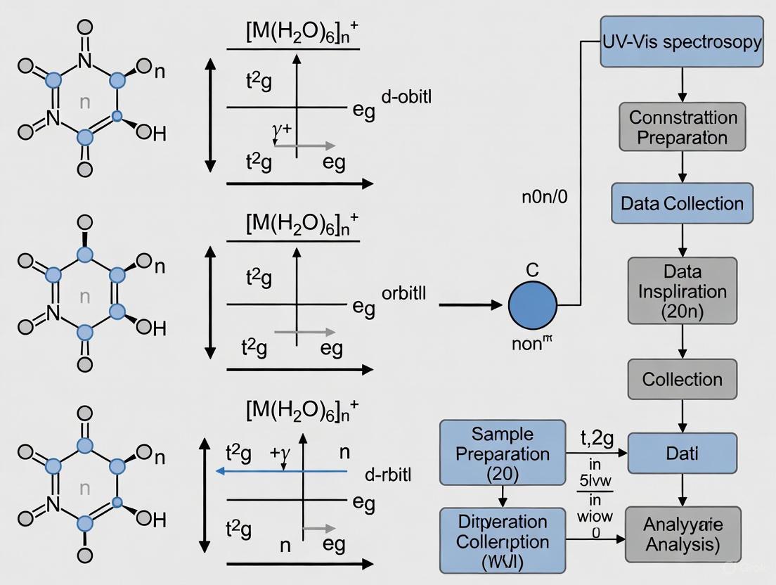
Visualization of Concepts and Workflows
UV-Vis Instrument Workflow
d-Orbital Splitting and Transitions
Research Reagent Solutions
Table 3: Essential Materials for d-d Transition Studies
| Reagent/Material | Function/Application | Key Considerations |
|---|---|---|
| Quartz Cuvettes | Sample holder for UV-Vis measurements | Essential for UV range; transparent down to 200 nm |
| Deuterium Lamp | UV light source (200-400 nm) | Requires warm-up time; limited lifetime |
| Tungsten/Halogen Lamp | Visible light source (350-800 nm) | Stable output; longer lifetime than deuterium lamps |
| Diffraction Grating | Wavelength selection in monochromator | 1200+ grooves/mm for optimal resolution |
| PMT Detector | Light detection and signal amplification | High sensitivity for low light levels |
| Standard Reference Materials | Instrument calibration and validation | Essential for quantitative accuracy |
| High-Purity Solvents | Sample preparation | Must be transparent in spectral region of interest |
| Nitrogen Purge System | Removal of oxygen for far-UV measurements | Prevents oxygen absorption below 200 nm |
Crystal Field Theory (CFT) provides a foundational model for understanding the electronic structures and resultant colors of transition-metal complexes. This theory posits that metal-ligand interactions are primarily electrostatic in nature, where electrons in the metal's d-orbitals experience repulsive forces from the electrons of the surrounding ligands [6]. The central focus of CFT is the effect of these interactions on the five valence d-orbitals, which are degenerate (of equal energy) in a free metal ion. In an octahedral complex, where a metal ion is surrounded by six ligands positioned at the corners of an octahedron, this degeneracy is removed. The negative charges from the ligands approach the metal ion directly along the Cartesian axes, leading to a characteristic splitting of the d-orbital energy levels [6]. This splitting is the origin of the crystal field stabilization energy (CFSE) and is directly responsible for the absorption of light in the visible spectrum, giving these complexes their characteristic colors [2] [6].
Theoretical Framework: d-Orbital Splitting and Electronic Transitions
The Octahedral Splitting Pattern
In an octahedral field, the five d-orbitals split into two distinct sets with different energies [6]:
- The e₉ set: This higher-energy set comprises the dx²-y² and dz² orbitals. These orbitals point directly toward the approaching ligands, resulting in greater electrostatic repulsion and higher energy.
- The t₂₉ set: This lower-energy set comprises the dxy, dxz, and dyz orbitals. These orbitals point between the axes, experiencing less repulsion from the ligands and thus stabilizing in energy.
The energy difference between these two sets is termed the crystal field splitting energy, denoted as Δₒ (where the subscript "o" stands for octahedral) [6]. The magnitude of Δₒ is not fixed; it depends critically on the identity of the metal ion (its oxidation state and position in the periodic table) and the chemical nature of the ligands. The total energy of the five d-orbitals remains unchanged by this splitting; the energy gain by the t₂₉ orbitals is exactly balanced by the energy loss of the e₉ orbitals [6].
d-d Transitions and UV-Vis Spectroscopy
The splitting of d-orbitals enables electronic transitions that can be probed using Ultraviolet-visible (UV-vis) spectroscopy. d-d transitions are electronic promotions of electrons between the metal-centered t₂₉ and e₉ molecular orbitals [2]. These transitions occur in the visible or near-UV region of the electromagnetic spectrum, which typically spans 200 to 800 nm (1.5 - 6.2 eV) [7]. When a complex absorbs light of a specific wavelength to excite an electron, the complementary color is perceived, which is the origin of color in these compounds. It is crucial to note that d-d transitions are only possible for metal ions with partially filled d-shells (d¹ to d⁹ configurations) [2]. Furthermore, these transitions are Laporte-forbidden, meaning they have relatively low transition probabilities. Consequently, d-d bands in a UV-vis spectrum appear as weak absorptions with molar absorptivity (ε) values typically less than 1,000 M⁻¹cm⁻¹ [2].
Table 1: Key Characteristics of Electronic Transitions in Coordination Compounds
| Transition Type | Origin of Transition | Spectral Band Intensity (ε / M⁻¹cm⁻¹) | Common Examples |
|---|---|---|---|
| d-d Transition | Between metal-centered orbitals (t₂₉ → e₉) | Weak (ε < 1,000) | [Ti(H₂O)₆]³⁺, [Cu(NH₃)₄]²⁺ |
| Charge Transfer (CT) | Between orbitals of different molecular entities | Strong (ε > 1,000) | CrO₄²⁻ (LMCT), [Ru(bpy)₃]²⁺ (MLCT) |
Experimental Protocols for UV-Vis Analysis of d-d Transitions
UV-vis spectroscopy is a pivotal technique for quantifying d-d transitions and determining the crystal field splitting energy, Δₒ. The following protocol outlines the steps for a quantitative analysis of an octahedral transition metal complex in solution.
Instrument Calibration and Sample Preparation
- Instrument Warm-up: Power on the UV-vis spectrophotometer and allow the deuterium or tungsten lamp to stabilize for at least 15-30 minutes [7].
- System Zeroing: Fill a high-quality quartz cuvette (path length, b, typically 1 cm) with the pure solvent used for the sample (e.g., water, acetonitrile). Place this in the sample holder and run a baseline correction or "blank" measurement to zero the instrument for the solvent [7].
- Sample Solution Preparation: Accurately prepare a stock solution of the transition metal complex. The complex must be soluble and form a true solution, as suspensions of solid particles will scatter light and produce skewed data [7].
- Calibration Curve Construction (for quantitative analysis): a. Using volumetric flasks and digital pipettes for accuracy, prepare a series of at least three, but ideally five, standard solutions of known concentration from the stock solution [7]. b. The concentration range should bracket the expected concentration of your unknown sample, spaced relatively equally apart [7]. c. Measure the absorbance of each standard solution at the wavelength of maximum absorption (λmax) for the d-d transition band.
Data Acquisition and Analysis
- Sample Measurement: Introduce the sample solution of unknown concentration into a clean cuvette and acquire its full absorbance spectrum across the UV-vis range (e.g., 800-200 nm) [7].
- Determine λmax: Identify the wavelength of the peak maximum for the d-d transition band from the sample spectrum.
- Calculate Δₒ: The crystal field splitting energy is directly calculated from the absorption maximum using the equation: Δₒ = hc / λmax where h is Planck's constant, c is the speed of light, and λmax is in meters. Often, Δₒ is reported in wavenumbers (cm⁻¹), calculated as: Δₒ (cm⁻¹) = 10⁷ / λmax (nm)
- Quantitative Concentration Determination (if applicable): a. Construct a calibration curve by plotting the absorbance values of the standard solutions at λmax against their known concentrations [7]. b. The data should fit a linear trend described by the Beer-Lambert Law: A = εbc, where A is absorbance, ε is the molar absorptivity, b is the path length, and c is the concentration [7]. c. Determine the correlation coefficient (R²); an acceptable calibration has R² ≥ 0.9 [7]. A lower value may indicate human error in solution preparation or an instrument issue. d. Use the linear equation of the calibration curve to calculate the concentration of the unknown sample based on its measured absorbance.
The Scientist's Toolkit: Essential Reagents and Materials
Table 2: Key Research Reagent Solutions and Materials for d-d Transition Analysis
| Item Name | Function/Application | Critical Specifications |
|---|---|---|
| High-Purity Transition Metal Salts | Source of the central metal ion for complex synthesis. | Salts like NiCl₂, CuSO₄, K₃[Fe(CN)₆]; purity >99% to avoid spectroscopic interference. |
| Ligand Solutions | To form the coordination complex with the metal ion. | e.g., 1,10-phenanthroline, ethylenediamine, cyanide salts; purity and concentration must be known. |
| Spectroscopic-Grade Solvents | To dissolve the complex for analysis without absorbing in the UV-vis range. | e.g., Acetonitrile, water (HPLC grade), hexanes; low UV cutoff. |
| Quartz Cuvettes | Holder for the sample solution during spectroscopic measurement. | Path length of 1 cm; transparent down to 200 nm (glass cuettes absorb UV light). |
| UV-Vis Spectrophotometer | Instrument for measuring light absorption by the sample. | Deuterium & tungsten lamps for full UV-vis range; monochromator or diode array detector [7]. |
Data Interpretation and Workflow Visualization
The following workflow diagram outlines the logical process from sample preparation to the determination of the crystal field splitting energy.
A critical step in data interpretation involves distinguishing d-d transitions from other electronic transitions. Charge transfer (CT) transitions occur between molecular orbitals that are primarily metal-based and those that are primarily ligand-based [2]. These transitions are fully allowed and consequently appear as very intense bands (ε > 1,000 M⁻¹cm⁻¹) in the UV-vis spectrum [2]. There are two types:
- Ligand-to-Metal Charge Transfer (LMCT): An electron is promoted from a ligand-based orbital to a metal-based orbital. Common with π-donor ligands.
- Metal-to-Ligand Charge Transfer (MLCT): An electron is promoted from a metal-based orbital to a ligand-based orbital. Common with π-acceptor ligands.
The following diagram illustrates the relationship between the crystal field splitting and the resulting spectroscopic transitions.
The analysis of d-d transitions through UV-vis spectroscopy, grounded in the principles of Crystal Field Theory, provides an indispensable tool for researchers investigating octahedral transition metal complexes. The precise measurement of the crystal field splitting energy, Δₒ, offers profound insights into the electronic structure of a complex, which in turn governs its magnetic properties, reactivity, and physiological function. In drug development, where metal complexes play roles as catalysts, structural elements, or active pharmaceutical ingredients, understanding these fundamental electronic properties is critical for rational design and optimization. The protocols and frameworks detailed in this application note provide a robust foundation for such advanced research and development efforts.
In the analysis of octahedral transition metal complexes using UV-Visible spectroscopy, understanding the intensity of absorption bands is paramount. The observed colors and absorption strengths are governed by fundamental quantum mechanical principles known as selection rules, which dictate the probability of electronic transitions between energy states. These rules provide the theoretical framework for interpreting spectroscopic data, particularly for the diagnostically important but often weak d-d transitions. The Laporte rule (or parity selection rule) states that in centrosymmetric molecules, electronic transitions that conserve parity are forbidden; specifically, transitions between states of the same symmetry (g → g or u → u) are electric dipole forbidden [8] [9]. This rule rigorously applies to atoms and molecules with an inversion centre, explaining why d-d transitions in perfectly octahedral complexes (where d orbitals are gerade) are formally forbidden yet appear weakly in experimental spectra.
Complementing the Laporte rule is the spin selection rule, which forbids transitions that involve a change in the spin multiplicity of the electronic state [8] [9]. According to this rule, singlet-to-singlet and triplet-to-triplet transitions are allowed, whereas singlet-to-triplet transitions are forbidden. Transitions that violate both the spin and Laporte selection rules result in exceptionally faint absorption bands, a characteristic feature of many octahedral Mn(II) and Fe(III) complexes [8]. The interplay between these rules and molecular symmetry forms the basis for predicting and interpreting the electronic spectra of coordination compounds, enabling researchers to extract valuable structural and electronic information from UV-Visible absorption measurements.
Theoretical Framework of Selection Rules
The Laporte Parity Rule
The Laporte selection rule is derived from the properties of the transition moment integral that governs the probability of an electronic transition. This integral takes the form ⟨ψₑ|H'|ψg⟩, where ψg and ψₑ are the wavefunctions of the ground and excited states respectively, and H' is the transition moment operator, typically the electric dipole operator [8]. The position operator (r) in the dipole moment operator is odd under parity (meaning it changes sign under inversion through the origin). For the transition moment integral to be non-zero, the integrand ψₑrψg must be even under parity. This condition is only satisfied when the ground and excited states have different parity (one gerade and one ungerade), making g→u or u→g transitions allowed, while g→g and u→u transitions are formally forbidden [8].
In atomic orbitals, s and d orbitals are gerade (symmetric under inversion), while p and f orbitals are ungerade (antisymmetric under inversion) [8]. Consequently, in atoms or centrosymmetric molecules such as perfect octahedral complexes, s→s, p→p, d→d, and f→f transitions are Laporte-forbidden. This rule most significantly impacts d-d transitions in transition metal complexes, which occur in the visible region and are of primary interest in coordination chemistry. It is crucial to recognize that the Laporte rule's strict application relies on the electric dipole approximation, which assumes the electromagnetic field's wavelength is much longer than the molecular dimensions. In reality, higher-order terms in the interaction Hamiltonian can permit weakly allowed transitions between states of the same parity [8].
The Spin Selection Rule
The spin selection rule dictates that electronic transitions must conserve spin angular momentum, forbidding transitions that involve a change in spin state [9]. In molecular term symbols, this translates to the requirement that ΔS = 0, meaning the spin multiplicity must remain constant during the transition. Thus, singlet-to-singlet (e.g., ¹A → ¹A) and triplet-to-triplet transitions are allowed, while singlet-to-triplet transitions (e.g., ¹A → ³A) are forbidden. This prohibition arises because the electric dipole operator does not act on electron spin, leaving the spin part of the wavefunction unchanged during the transition.
The spin rule has profound implications for transition metal complexes, particularly those with high-spin configurations. When both the Laporte and spin selection rules are violated, extinction coefficients become extremely small (ε < 1), making spectroscopic detection challenging. This combined effect explains why complexes like [Mn(H₂O)₆]²⁺ and [Fe(H₂O)₆]³⁺ exhibit such pale colors despite having partially filled d-orbitals [8] [10]. The faintness of these transitions necessitates higher sample concentrations or longer path lengths for reliable detection in experimental studies of octahedral complexes.
Mechanisms for Rule Relaxation
Although d-d transitions in octahedral complexes are formally forbidden by the Laporte rule, they are observed experimentally with weak but measurable intensities due to several mechanisms that relax these strict selection rules:
Vibronic Coupling: Asymmetric molecular vibrations temporarily disrupt the centrosymmetry of the complex, creating a vibronic state with mixed parity that provides a pathway for weakly allowed transitions [8]. This coupling between vibrational and electronic wavefunctions enables formally forbidden d-d transitions to gain intensity, typically resulting in extinction coefficients (ε) below 100 L mol⁻¹ cm⁻¹ [8].
Symmetry Lowering: Static molecular distortions from ideal Oh symmetry, whether through Jahn-Teller effects or asymmetric ligand substitution, can partially relax the Laporte rule [8]. For instance, the complex [Cr(NH₃)₅Cl]²⁺ possesses only C4v symmetry yet still maintains a centre of inversion, exhibiting weak d-d transitions (ε < 100) that demonstrate how subtle symmetry changes affect transition intensities without complete loss of centrosymmetry [8].
d-p Mixing: In non-centrosymmetric point groups such as tetrahedral (Td), the absence of an inversion centre permits mixing between d orbitals (gerade) and p orbitals (ungerade), creating molecular orbitals of mixed parity that allow stronger d-d transitions [8]. This explains why tetrahedral complexes like [CoCl₄]²⁻ exhibit significantly more intense absorptions (ε ≈ 600) compared to their octahedral analogues [8].
Table 1: Transition Types and Their Characteristic Intensities in UV-Visible Spectroscopy
| Transition Type | Selection Rule Status | Typical ε (L mol⁻¹ cm⁻¹) | Example |
|---|---|---|---|
| Spin-forbidden, Laporte-forbidden | Violates both rules | ~0.1 | [Mn(H₂O)₆]²⁺ [10] |
| Spin-allowed, Laporte-forbidden | Violates parity rule only | 5-200 | [Co(H₂O)₆]²⁺ (ε ≈ 10) [8] |
| Spin-allowed, Laporte-allowed | Partially relaxed (vibronic) | < 100 | [Cr(NH₃)₅Cl]²⁺ [8] |
| Spin-allowed, Laporte-allowed | No inversion center | ~600 | [CoCl₄]²⁻ [8] |
| Charge Transfer | Fully allowed | > 1,000 | MLCT, LMCT [11] [2] |
Chromophores in Coordination Chemistry
d-d Transitions
d-d transitions represent electronic promotions between metal-centered orbitals that are primarily d-orbital in character, specifically between the crystal field splitting components (t₂g and e_g orbitals in octahedral geometry) [11] [2]. These transitions are only possible in complexes with partially filled d-shells (d¹ to d⁹ configurations) and provide direct information about the ligand field splitting parameter (Δₒ). In UV-visible spectra, d-d transitions typically appear as relatively weak, often broad bands with extinction coefficients generally below 1,000 L mol⁻¹ cm⁻¹, reflecting their formally forbidden nature [11] [2]. The broadening arises from vibrational fine structure and the rapid non-radiative decay pathways available to excited states in complex systems.
The energy and splitting patterns of d-d transitions serve as sensitive indicators of coordination geometry, oxidation state, and ligand identity. For a given metal ion, the spectral features change systematically with ligand field strength according to the spectrochemical series, enabling researchers to make informed assignments of complex structures. The weak intensity of these transitions, while challenging for detection, provides valuable diagnostic information about molecular symmetry and the extent to which selection rules are relaxed in real chemical systems.
Charge Transfer Transitions
In contrast to d-d transitions, charge transfer (CT) transitions involve electron promotion between molecular orbitals that are predominantly metal-centered to those that are predominantly ligand-centered, or vice versa [11] [2]. These transitions produce exceptionally intense absorption bands with extinction coefficients typically exceeding 1,000 L mol⁻¹ cm⁻¹, as they involve a substantial redistribution of electron density and are fully allowed by both Laporte and spin selection rules [11] [2]. There are two primary classes of charge transfer transitions relevant to coordination chemistry:
Ligand-to-Metal Charge Transfer (LMCT): These transitions occur when electrons are promoted from molecular orbitals primarily localized on the ligand to those primarily localized on the metal ion [11] [2]. LMCT transitions are typically observed in complexes with π-donor ligands (e.g., halides, OH⁻) and metals in high oxidation states that can readily accept electron density.
Metal-to-Ligand Charge Transfer (MLCT): These transitions involve electron promotion from metal-centered orbitals to ligand-centered orbitals [11] [2]. MLCT bands are characteristic of complexes with π-acceptor ligands (e.g., CO, CN⁻, bipyridine) and metals in low oxidation states that can readily donate electron density.
Charge transfer transitions often dominate UV-visible spectra due to their high intensities and frequently occur in the ultraviolet region, though they may extend into the visible region and impart intense colors to coordination compounds. Their diagnostic value lies in providing information about the relative energy levels of metal and ligand orbitals and the covalent character of metal-ligand bonding.
Table 2: Comparison of Electronic Transition Types in Transition Metal Complexes
| Feature | d-d Transitions | Charge Transfer Transitions |
|---|---|---|
| Orbital Origin | Metal-centered to metal-centered | Metal to ligand or ligand to metal |
| Selection Rules | Laporte-forbidden (weak) | Laporte-allowed (strong) |
| Extinction Coefficient (ε) | < 1,000 L mol⁻¹ cm⁻¹ | > 1,000 L mol⁻¹ cm⁻¹ |
| Band Width | Broad | Usually broad, sometimes sharp |
| Information Provided | Ligand field strength, geometry | Covalency, orbital energy alignment |
| Dependence on Symmetry | High (centrosymmetric complexes forbidden) | Low (always allowed) |
Experimental Protocols for d-d Transition Analysis
Sample Preparation and Measurement
The accurate characterization of d-d transitions in octahedral complexes requires careful sample preparation and spectroscopic measurement. The following protocol outlines a standardized approach for obtaining high-quality UV-visible spectra of transition metal complexes:
Solvent Selection: Choose spectroscopically transparent solvents that do not absorb in the spectral region of interest. Common choices for octahedral complexes include water, acetonitrile, and dimethyl sulfoxide (DMSO), which have minimal absorption in the visible and near-UV regions [12]. For non-aqueous complexes, spectroscopic-grade hexane or dichloromethane may be employed. The solvent should not coordinate strongly enough to displace the ligands of interest or alter the complex geometry.
Sample Concentration Optimization: Prepare solutions with concentrations typically in the range of 1-50 mM for d-d transition analysis, as their weak extinction coefficients require higher concentrations for detection [8] [11]. For intense charge transfer bands that may appear in the same spectrum, dilute aliquots (0.01-0.1 mM) may be necessary to avoid detector saturation. Perform serial dilutions to identify optimal concentrations for different spectral regions if a single concentration yields saturated (A > 2) or weak (A < 0.1) absorptions.
Cuvette Selection and Handling: Use 1 cm pathlength quartz cuvettes for UV-visible measurements, as quartz provides transmission across the full spectral range (200-800 nm). Ensure cuvettes are meticulously cleaned with appropriate solvents and dried before use. For air-sensitive complexes, employ sealed or Schlenk-type cuvettes with septa for anaerobic measurements. Always handle cuvettes by their opaque sides to avoid fingerprints in the light path.
Spectrometer Parameters: Configure the spectrophotometer with a scan speed of 100-500 nm/min, data interval of 0.5-1 nm, and spectral bandwidth of 1-2 nm for optimal resolution of d-d bands. Perform baseline correction with a solvent-filled cuvette before sample measurement. For low-temperature studies, utilize a cryostat attachment and cool samples to 77K using liquid nitrogen to reduce vibrational broadening and enhance resolution of d-d transitions.
Data Analysis and Interpretation
Once high-quality spectra are acquired, systematic analysis enables extraction of meaningful chemical information about the octahedral complex under investigation:
Baseline Correction and Normalization: Apply linear baseline correction to account for any instrumental drift or light scattering effects. Normalize spectra to concentration and pathlength using the Beer-Lambert law (A = εcl) to obtain molar absorptivity (ε) values, enabling quantitative comparison between different complexes.
Band Deconvolution: Employ Gaussian or Lorentzian fitting algorithms to deconvolute overlapping absorption bands, particularly important for d-d transitions which often appear as composite features due to Jahn-Teller distortions or low-symmetry components [8]. The number, position, and intensity of these component bands provide information about the electronic structure and symmetry of the complex.
Spectrochemical Series Determination: Identify the wavelength of maximum absorption (λmax) for each d-d transition and calculate the corresponding energy in wavenumbers (cm⁻¹ = 1/λmax). For simple octahedral complexes with a single d-d transition, this energy corresponds directly to the ligand field splitting parameter Δₒ. Plotting these energies against the position of ligands in the spectrochemical series validates assignments and may reveal deviations from ideal octahedral symmetry.
The following workflow diagram illustrates the complete experimental process from sample preparation to data interpretation:
The Scientist's Toolkit: Essential Research Reagents and Materials
Successful analysis of chromophores and selection rules in octahedral complexes requires specific laboratory reagents and materials. The following table details essential components of the research toolkit for these investigations:
Table 3: Essential Research Reagents and Materials for d-d Transition Analysis
| Item | Specification | Function/Application |
|---|---|---|
| Transition Metal Salts | High-purity (>99%), anhydrous when required | Synthesis of octahedral complexes with defined metal centers (e.g., Co(II), Cr(III), Ni(II)) |
| Spectroscopic Solvents | UV-vis grade with low absorbance in region of interest | Sample preparation without interfering absorption bands (water, acetonitrile, DMSO) |
| Quartz Cuvettes | 1 cm pathlength, UV-vis compatible | Housing samples for spectroscopic measurement with full spectral range transmission |
| UV-Vis Spectrophotometer | Double-beam configuration, 200-800 nm range | Accurate measurement of absorption spectra with baseline correction capability |
| Ligand Series | Varying field strength (H₂O, NH₃, CN⁻, etc.) | Constructing spectrochemical series and investigating ligand effects on Δₒ |
| Cryostat Attachment | Liquid nitrogen cooled (77K capability) | Low-temperature measurements to reduce vibrational broadening |
| Software Packages | Spectral analysis with curve-fitting capability | Deconvolution of overlapping bands and quantitative intensity measurements |
Advanced Applications and Protocol Variations
Low-Temperature Spectroscopy
The implementation of low-temperature UV-visible spectroscopy at 77K using liquid nitrogen cryostats significantly enhances the resolution of d-d transitions by reducing thermal broadening effects [12]. This technique reveals vibrational fine structure that is obscured at room temperature and allows for more accurate determination of transition energies and intensities. The sharpening of spectral features enables better resolution of closely spaced transitions and provides evidence for Jahn-Teller distortions through the appearance of split bands that may be indistinguishable at higher temperatures. Low-temperature studies are particularly valuable for quantifying the extent of vibronic coupling by comparing band intensities between room temperature and cryogenic measurements.
Polarized Single-Crystal Spectroscopy
For complete characterization of transition dipole moments and symmetry assignments, polarized single-crystal spectroscopy provides the most definitive approach. By measuring absorption spectra with light polarized along different molecular axes within a single crystal, researchers can determine the symmetry properties of excited states and make unambiguous assignments of d-d transitions to specific electronic promotions. This technique is particularly powerful for distinguishing between transitions that are formally Laporte-forbidden but gain intensity through specific vibrational modes or symmetry lowering in the solid state. While requiring specialized instrumentation and high-quality single crystals, this approach yields the most detailed electronic structure information available from UV-visible spectroscopy.
Time-Resolved Studies
Time-resolved UV-visible spectroscopy extends static measurements to the temporal domain, enabling investigation of excited-state dynamics following d-d excitation. Using pulsed laser systems with nanosecond to femtosecond time resolution, researchers can track the relaxation pathways of electronically excited states, including energy transfer processes, intersystem crossing, and photochemical transformations. These studies provide direct insight into the fate of energy absorbed during "forbidden" transitions and help explain the relationship between transition probability and photochemical reactivity in coordination compounds. Time-resolved techniques are particularly valuable for investigating spin-forbidden transitions that may involve long-lived excited states with potential applications in photocatalysis and molecular devices.
The following diagram illustrates the symmetry relationships and transition probabilities governed by the selection rules discussed in this application note:
This application note provides a detailed framework for employing UV-Visible spectroscopy in the quantitative analysis of d-d transitions in octahedral coordination complexes. Within the context of advanced materials and drug development research, where such metal complexes are prevalent, the accurate interpretation of spectroscopic data is paramount. This guide details the core principles of the Beer-Lambert Law, defines its key parameters—absorbance and molar absorptivity—and presents standardized protocols for instrument calibration, sample preparation, and data analysis. Special emphasis is placed on the unique characteristics of d-d transitions, including their typically low intensity and the critical influence of the ligand field. The protocols and methodologies outlined herein are designed to equip researchers and scientists with the tools necessary for rigorous spectroscopic characterization, ensuring reliable and reproducible results in their investigations.
The Beer-Lambert Law
The Beer-Lambert Law (also known as Beer's Law) is the fundamental relationship that describes the attenuation of light as it passes through an absorbing substance [13]. It is an indispensable tool for the quantitative analysis of solutions in spectroscopic research. The law establishes a linear relationship between the absorbance (A) of a sample and the concentration (c) of the absorbing species, as well as the path length (l) the light travels through. The modern formulation of this law is expressed in Equation 1 [13] [14]:
A = ε * c * l (Equation 1)
In this equation, ε represents the molar absorption coefficient (also historically called molar absorptivity or molar extinction coefficient), c is the molar concentration of the analyte, and l is the path length of the light through the sample, typically measured in cm [13] [14]. Absorbance itself is a dimensionless quantity defined from the ratio of the incident light intensity (I₀) to the transmitted light intensity (I), as shown in Equation 2 [13] [15]:
A = log₁₀ (I₀ / I) (Equation 2)
The following diagram illustrates the core concepts and the logical workflow connecting the measurement to the final determination of concentration using the Beer-Lambert Law.
Distinguishing d-d and Charge Transfer Transitions
In the study of transition metal complexes, it is critical to differentiate between two primary types of electronic transitions observed in UV-Vis spectra, as they have distinct intensities and underlying mechanisms [2].
d-d Transitions: These occur between molecular orbitals that are primarily metal-based in character—specifically, between the split d-orbitals in a crystal field (e.g., from t₂g to e_g in an octahedral complex) [2]. These transitions are Laporte-forbidden and thus have characteristically low molar absorptivity values (ε < 1,000 M⁻¹cm⁻¹) [2]. The energy of these transitions provides direct insight into the crystal field splitting parameter (Δₒ).
Charge Transfer (CT) Transitions: These are electronic transitions between molecular orbitals that are predominantly localized on the metal to those localized on the ligand, or vice versa. They are categorized as:
- Ligand-to-Metal Charge Transfer (LMCT): Electron transition from a ligand-based orbital to a metal-based orbital.
- Metal-to-Ligand Charge Transfer (MLCT): Electron transition from a metal-based orbital to a ligand-based orbital. Charge transfer transitions are formally allowed and consequently exhibit very high intensity, with molar absorptivity values often exceeding 10,000 M⁻¹cm⁻¹ [2]. The intense purple color of permanganate (KMnO₄) is a classic example of an LMCT transition [16].
Table 1: Key Differences Between d-d and Charge Transfer Transitions
| Feature | d-d Transition | Charge Transfer Transition |
|---|---|---|
| Origin | Transition between metal-centered d-orbitals | Electron transfer between metal and ligand orbitals |
| Selection Rule | Laporte-forbidden | Laporte-allowed |
| Typical Molar Absorptivity (ε) | < 1,000 M⁻¹cm⁻¹ [2] | > 10,000 M⁻¹cm⁻¹ [2] |
| Band Width | Relatively broad | Often broad, can be sharp |
| Dependence on Geometry | Strong (e.g., Octahedral vs. Tetrahedral) | Less direct dependence |
Key Parameters and Their Interpretation
Molar Absorptivity (ε)
The molar absorption coefficient (ε) is an intrinsic property of a chemical species at a given wavelength and under specific conditions (solvent, temperature, pH) [14] [17]. It is a measure of the probability of an electronic transition; a high ε value indicates a highly probable (allowed) transition. The IUPAC recommends the term "molar absorption coefficient" over older terms like "molar absorptivity" or "molar extinction coefficient," which are now discouraged [14] [17]. The SI unit for ε is m²/mol, but it is most commonly reported in practical research as M⁻¹cm⁻¹ (which is equivalent to 0.1 m²/mol) [14].
Absorbance (A) and Transmittance (T)
Absorbance (A) is the primary measured quantity in a UV-Vis experiment and is directly related to the concentration of the analyte via the Beer-Lambert Law [13]. Transmittance (T) is the ratio of the transmitted to the incident light intensity (I/I₀) and is often expressed as a percentage [15]. The relationship between absorbance and percent transmittance is logarithmic, as detailed in Table 2.
Table 2: Relationship Between Absorbance and Transmittance
| Absorbance (A) | Transmittance (T) | % Transmittance (%T) | Light Transmitted |
|---|---|---|---|
| 0 | 1 | 100% | 100% |
| 0.1 | ~0.79 | ~79% | 79% |
| 0.3 | 0.5 | 50% | 50% |
| 1 | 0.1 | 10% | 10% [13] [15] |
| 2 | 0.01 | 1% | 1% [15] |
| 3 | 0.001 | 0.1% | 0.1% [15] |
For reliable quantitative analysis, it is recommended to maintain absorbance readings within the dynamic range of the instrument, typically between 0.1 and 1.0 [1]. Absorbance values significantly above 1 (meaning less than 10% transmittance) can lead to unreliable quantitation due to insufficient light reaching the detector [1].
Experimental Protocols
Protocol 1: Calibration Curve Method for Determining Unknown Concentration
This is the standard method for quantifying an analyte of known identity but unknown concentration in solution.
Workflow Overview:
Materials and Reagents:
- Solute: High-purity transition metal complex (e.g., [Ti(H₂O)₆]³⁺).
- Solvent: High-purity, UV-transparent solvent appropriate for the complex (e.g., water, acetonitrile). The solvent must not absorb significantly in the spectral region of interest.
- Volumetric Flasks: Class A, for accurate preparation of standard solutions.
- Cuvettes: Quartz, with a defined path length (e.g., 1.00 cm). Quartz is essential for UV light transmission [1]. Ensure cuvettes are clean and free of scratches.
Step-by-Step Procedure:
- Preparation of Standard Solutions:
- Accurately prepare a stock solution of the metal complex with a known, precise concentration.
- Using serial dilution, prepare at least five standard solutions of varying, known concentrations that bracket the expected concentration of the unknown sample [15]. This verifies the linearity of the Beer-Lambert Law for your system.
Spectroscopic Measurement:
- Zero the spectrophotometer using a blank cuvette filled only with the pure solvent.
- Measure the absorbance of each standard solution at its λ_max (wavelength of maximum absorbance). For d-d transitions, this will be in the visible region. Perform each measurement in triplicate.
Calibration Curve Construction:
- Plot the average absorbance (y-axis) against the corresponding known concentration (x-axis) for each standard.
- Perform linear regression analysis (y = mx + b) to obtain the best-fit line. The slope of this line is equal to εl.
Analysis of the Unknown:
- Measure the absorbance of the unknown sample at the same λ_max and under identical instrumental conditions.
- Use the equation of the calibration curve to calculate the concentration of the unknown: c_unknown = (A_unknown - b) / m.
Protocol 2: Determination of Molar Absorptivity (ε) for a Novel Complex
This protocol is used to characterize a newly synthesized or poorly documented coordination complex.
Step-by-Step Procedure:
- Prepare a Master Solution:
- Accurately weigh a known mass of the pure, dry complex.
- Dissolve it in a known volume of solvent to create a master solution of precise molar concentration (c_master).
Measure Absorbance and Path Length:
- Measure the absorbance (A) of the master solution at λ_max using a quartz cuvette of a known, precise path length (l). A standard path length is 1.000 cm.
Calculate Molar Absorptivity:
- Apply the Beer-Lambert Law directly to calculate ε: ε = A / (c * l).
- Report the value with units of M⁻¹cm⁻¹, and specify the solvent and wavelength (e.g., ε = 150 M⁻¹cm⁻¹ in H₂O at 510 nm).
Important Note: Relying on a single literature value for ε for quantitative analysis is not recommended. It is always preferable to determine ε experimentally under your specific laboratory conditions [17].
The Scientist's Toolkit: Research Reagent Solutions
Table 3: Essential Materials and Reagents for UV-Vis Analysis of Coordination Complexes
| Item | Function & Importance | Technical Specifications |
|---|---|---|
| Quartz Cuvettes | Sample holder for spectroscopic measurement. | Path length: 1.00 cm (standard). Quartz is mandatory for UV light transmission (below ~350 nm); glass or plastic cuvettes are unsuitable as they absorb UV light [1]. |
| High-Purity Solvents | To dissolve the analyte without interfering with the measurement. | Must be UV-transparent (spectrophotometric grade). Common choices include water, acetonitrile, and methanol. The solvent cutoff wavelength must be lower than the analyte's λ_max. |
| Volumetric Glassware | For accurate preparation of standard and sample solutions. | Class A certified for high precision and minimal tolerance. |
| Deuterium & Tungsten Lamps | Light sources in the spectrophotometer. | The deuterium lamp covers the UV range, and the tungsten/halogen lamp covers the visible range. The instrument automatically switches between them during a scan [1]. |
| Blank Solution | A reference to correct for solvent and cuvette absorbance. | Consists of the pure solvent used to prepare the sample, contained in an identical cuvette. Its signal is subtracted to report the true absorbance of the analyte [1]. |
Data Analysis and Troubleshooting
Calculating the Octahedral Splitting Energy (Δₒ)
For d-d transitions in octahedral complexes, the wavelength of maximum absorption (λ_max) is directly related to the crystal field splitting parameter, Δₒ. The energy of the transition is calculated using Equation 3, and subsequently, Δₒ is determined.
E = hc / λ_max (Equation 3)
Where:
- E is the energy of the transition (in Joules).
- h is Planck's constant (6.626 × 10⁻³⁴ J·s).
- c is the speed of light (3.00 × 10⁸ m/s).
- λ_max is the wavelength of maximum absorption (in meters).
Example Calculation: The [Ti(H₂O)₆]³⁺ complex absorbs light at 498 nm. The octahedral splitting energy is calculated as follows [16]:
- E = (6.626 × 10⁻³⁴ J·s) × (3.00 × 10⁸ m/s) / (498 × 10⁻⁹ m)
- E ≈ 3.99 × 10⁻¹⁹ J
- Δₒ = E ≈ 4.00 × 10⁻¹⁹ J (This value can also be converted to kJ/mol or cm⁻¹ for comparison with literature values).
Troubleshooting Common Issues
Table 4: Common Experimental Challenges and Solutions
| Problem | Potential Cause | Recommended Solution |
|---|---|---|
| Non-linear Calibration Curve | High analyte concentration, molecular association, instrumental limitations [18] [1]. | Dilute samples to ensure A < 1. Verify the linear range for your specific compound. |
| Negative Absorbance | The blank has a higher absorbance than the sample. | Ensure the blank is chemically identical to the sample solvent and that the cuvettes are perfectly matched and clean. |
| High Signal Noise | Insufficient light reaching the detector, dirty cuvettes, light scattering. | Use a shorter path length cuvette for concentrated samples, clean cuvettes properly, and filter samples if colloidal particles are present [1]. |
| Spectral Bands Are Too Weak | d-d transitions are inherently weak (forbidden); low concentration. | Confirm the complex is in the correct d-electron configuration (d¹ to d⁹). Increase the sample concentration or use a cuvette with a longer path length. |
| Deviation from Beer's Law | Chemical effects (e.g., polymerization, oxidation) or optical effects (stray light, fluorescence) [18]. | Verify the chemical stability of the complex over the measurement time. Use high-quality instrumentation and appropriate filters. |
Within the broader context of research on d-d transition analysis in octahedral complexes using UV-Vis spectroscopy, this study provides a consolidated reference on the spectral signatures of three common transition metal ions: Cu(II), Ni(II), and Fe(III). The analysis of d-d transitions is a cornerstone of inorganic chemistry, providing critical insights into the geometric and electronic structure of metal complexes, which is paramount for applications in catalysis, material science, and drug development [3]. The characteristic colors of transition metal complexes originate from the excitation of d-orbital electrons from a lower energy level to a higher one within the split d-orbitals of an octahedral ligand field [3]. The specific energies of these transitions are exquisitely sensitive to the metal's identity, oxidation state, and the nature of its surrounding ligands, making UV-Vis spectroscopy a powerful diagnostic tool [3] [19]. This application note summarizes key quantitative spectral data and provides detailed protocols for researchers to reliably obtain and interpret these signatures.
The spectral behavior of Cu(II), Ni(II), and Fe(III) in octahedral coordination environments is distinct, reflecting their unique electronic configurations (d⁹, d⁸, and d⁵, respectively). Table 1 consolidates key spectral characteristics for these ions based on experimental data, while Table 2 outlines the influence of experimental conditions on their spectra.
Table 1: Spectral Characteristics of Selected Octahedral Ions
| Metal Ion & Electronic Configuration | Example Complex | Observed Color | Absorption Wavelength (λmax) | Approximate Absorption Region | Reference |
|---|---|---|---|---|---|
| Cu(II) (d⁹) | [Cu(H₂O)₆]²⁺ |
Pale blue | ~780 nm | Red region | [20] |
[Cu(NH₃)₄(H₂O)₂]²⁺ |
Dark blue | ~650 nm | Yellow-orange-red region | [20] | |
| Ni(II) (d⁸) | Ni²⁺ in aqueous perchlorate/triflate |
Not specified | ~400 nm, ~720 nm (at 150°C) | Visible to Near-IR | [21] |
NiCl⁺ complex |
Not specified | Systematic "red-shift" | Visible region | [21] | |
| Fe(III) (d⁵) | High-spin Fe(III)-CDO (Cys-bound) | Data from spectroscopy | Features characteristic of direct S-ligation | Not specified | [22] |
Table 2: Influence of Experimental Conditions on Spectral Data
| Factor | Effect on UV-Vis Spectrum | Example |
|---|---|---|
| Ligand Identity | Changes the crystal field splitting energy (Δ₀), causing a shift in λmax. Stronger field ligands increase Δ₀, leading to a shift to higher energy (shorter wavelength). | Replacing H₂O (weaker field) with NH₃ (stronger field) in Cu(II) complexes shifts λmax from 780 nm to 650 nm [20]. |
| Temperature | Can cause a "red-shift" (shift to longer wavelength) in absorption peaks due to changes in ligand field strength and complex stability. | Aqueous Ni²⁺ shows a red-shift with increasing temperature from 26°C to 250°C [21]. |
| Chloride Concentration | Formation of chloride complexes (e.g., NiCl⁺, NiCl₂(aq), NiCl₃⁻) leads to a systematic red-shift in the spectrum. | Spectra of nickel chloride solutions show a systematic red-shift with increasing chloride concentration [21]. |
Experimental Protocols
Sample Preparation
3.1.1 Synthesis of Bis(ethylenediamine) Copper(II) Complexes
- Objective: To prepare single crystals of octahedral
[Cu(en)₂(H₂O)₂]²⁺complex salts for structural and spectral analysis [19]. - Materials: Copper sulfate pentahydrate, sodium salt of the desired carboxylic acid (e.g., 2-phenoxybenzoic acid, diphenylacetic acid), ethylenediamine, methanol, water.
- Procedure:
- React copper sulfate pentahydrate with a two-molar equivalent of the sodium salt of the carboxylic acid in aqueous medium to form a precipitated copper(II) carboxylate.
- Separate the precipitated product and dissolve/suspend it in a methanol-water solution.
- Add ethylenediamine to the suspension and allow the mixture to stand for slow evaporation at room temperature.
- Collect the resulting single crystals after several days and dry them in air [19].
3.1.2 Preparation of Fe(III)-CDO for Spectroscopic Study
- Objective: To prepare substrate-bound Fe(III) cysteine dioxygenase (CDO) for characterizing its electronic structure.
- Materials: Purified CDO protein, HEPES buffer (25 mM, 200 mM NaCl, pH 7.5), cysteine or selenocysteine substrate.
- Procedure:
- Determine protein concentration spectrophotometrically (ε₂₈₀ = 25,300 M⁻¹cm⁻¹) and iron content via a colorimetric assay.
- Prepare the sample anaerobically with a final CDO concentration of ~1 mM (by Fe) in buffer.
- Add a two-fold excess of cysteine (or selenocysteine) to the anaerobic sample to form the substrate-bound complex [22].
UV-Vis Spectral Measurement
3.2.1 Data Acquisition for Solution Complexes
- Instrumentation: UV-Vis spectrophotometer (e.g., Cary 100 Bio, Varian Cary 5e).
- Procedure:
- Prepare a solution of the complex in an appropriate solvent (e.g., water, DMSO) at a concentration of ~1 × 10⁻³ M [23].
- Place the solution in a suitable cuvette (e.g., path length of 1 cm).
- Acquire the absorption spectrum across the UV-Vis range (e.g., 350-800 nm) [21].
- For temperature-dependent studies, use a high-temperature flow-through cell with precise temperature control (±0.5 °C) and collect spectra at desired temperatures [21].
3.2.2 Analysis of Spectral Data
- Beer-Lambert Law: Analyze the absorbance (A) using the equation
A = εlc, whereεis the molar absorptivity,lis the path length, andcis the concentration [3] [21]. - Complex Speciation: For systems in equilibrium, use the Beer-Lambert law in a multi-component form:
A/l = Σ [M_i] ε_i, where[M_i]andε_iare the concentration and molar absorptivity of the i-th species, respectively. This allows for the determination of formation constants for complexes like NiCl⁺ [21].
Signaling Pathways and Workflows
The process of synthesizing a complex and relating its molecular and electronic structure to its spectral output can be visualized as a workflow. Furthermore, the origin of the spectral signatures themselves is rooted in the electronic transitions within the metal center.
Research Workflow for Spectral Analysis
Electronic Transitions and Color
The Scientist's Toolkit: Research Reagent Solutions
Table 3: Essential Reagents and Materials for Octahedral Complex Synthesis and Analysis
| Reagent/Material | Function in Research | Example Application / Note |
|---|---|---|
| Ethylenediamine (en) | A common bidentate N-donor ligand used to model protein-metal interactions and form stable chelate complexes. | Used to synthesize model copper(II) complexes like [Cu(en)₂(H₂O)₂]²⁺ [19]. |
| Schiff Base Ligands | A class of ligands with an azomethine group (-C=N-); versatile for creating complexes with diverse geometrical features and biological activity. | Used in synthesizing mixed-ligand V(III), Fe(III), and Ni(II) complexes for antimicrobial studies [23]. |
| 2-Amino-4-methylpyrimidine (AMPY) | A heterocyclic ligand; its derivatives are crucial for understanding metal ion binding in biological systems due to their presence in nucleic acids. | Serves as a co-ligand in mixed-ligand complexes with Schiff bases [23]. |
| Copper(II) Sulfate Pentahydrate | A common, versatile precursor for synthesizing a wide range of copper(II) complexes. | Starting material for the synthesis of copper(II) carboxylate and ethylenediamine complexes [19]. |
| High-Temperature Spectroscopic Cell | Allows for the acquisition of UV-Vis spectra under controlled, elevated temperatures and pressures. | Critical for studying metal speciation in hydrothermal fluids or molten salts [21] [24]. |
| Density Functional Theory (DFT) | A computational method used to model and predict the geometric and electronic structure of metal complexes, supporting experimental spectral data. | Used to optimize structures and interpret electronic transitions in Cu(proline)₂ and Fe-CDO complexes [25] [22]. |
From Theory to Bench: Practical Protocols for Complex Characterization and Biomedical Applications
Purpose and Scope
This Standard Operating Procedure (SOP) outlines the detailed methodology for the preparation of metal complex samples and their subsequent measurement via Ultraviolet-Visible (UV-Vis) spectroscopy. This protocol is specifically designed for the analysis of d-d transitions in octahedral transition metal complexes, which is a fundamental technique in inorganic chemistry and pharmaceutical development research [3]. The procedures ensure consistent, reproducible results for quantifying electronic transitions, characterizing ligand field parameters, and determining complex stoichiometry.
The primary application within this context is the investigation of the electronic spectra of transition metal compounds and complexes, with a particular focus on how the splitting of d-orbitals in an octahedral field gives rise to characteristic absorption bands [3]. This protocol is essential for researchers and scientists engaged in the synthesis and characterization of novel metal-based compounds for analytical and therapeutic applications.
Theory and Principles
In UV-Vis spectroscopy, d-d transitions occur when an electron in a d-orbital of a transition metal ion is excited by light to a higher energy d-orbital [3]. In an octahedral complex, the degeneracy of the metal's d-orbitals is lifted, splitting them into lower-energy (t₂g) and higher-energy (e_g) sets. The energy difference between these sets is the ligand field splitting parameter, Δ₀ [3].
The wavelength of light absorbed corresponds to this energy gap and is influenced by the identity of the metal ion, its oxidation state, and the nature of the ligands [3]. The complimentary color observed is opposite the absorbed wavelength on the color wheel [12]. Furthermore, the intensity of d-d transitions is governed by selection rules; transitions that are spin-forbidden or symmetry-forbidden (in complexes with a center of inversion) typically have low molar absorptivity (ε) [3]. It is crucial to differentiate these d-d transitions from more intense charge transfer (CT) bands, which involve electron transfer between the metal and ligand orbitals [26].
Reagents and Materials
Table 1: Essential Research Reagent Solutions and Materials
| Item | Function/Explanation |
|---|---|
| Transition Metal Salts (e.g., Cu(II), Co(II), Ni(II) chlorides or acetates) | The source of the metal ion for complex formation. The choice of metal and its oxidation state directly determines the d-electron configuration and the resulting d-d transition energies [27] [28]. |
| Schiff Base Ligands (e.g., derived from salicylaldehyde and amines) | Common chelating ligands that form stable complexes with transition metals. Their strong chromophore activity facilitates detection and their structure influences the ligand field strength [27] [28]. |
| Anhydrous Ethanol & Methanol | High-purity, anhydrous solvents are used for the synthesis and dissolution of complexes to prevent hydrolysis or unwanted side reactions [27] [28]. |
| Dimethyl Sulfoxide (DMSO) & Dimethylformamide (DMF) | High-polarity, aprotic solvents commonly used to prepare stock solutions of metal complexes for spectroscopic analysis due to their excellent solvating power [27]. |
| Spectroscopic-Grade Solvents (e.g., Acetonitrile, Hexane) | Used for dilution and final sample preparation. High purity is required to avoid interfering absorbances in the UV region [12]. |
| Glacial Acetic Acid | Used as a catalytic agent in the synthesis of Schiff base ligands via condensation reactions [27] [28]. |
Equipment and Instrumentation
- UV-Vis Spectrophotometer (e.g., Shimadzu UV-2600) with matched quartz cuvettes (path length typically 1.0 cm)
- Analytical Balance (precision ±0.0001 g)
- Ultrasonic Bath
- Volumetric Flasks (Class A, various sizes)
- Micropipettes
- Filtration Assembly (0.45 μm or 0.2 μm syringe filters)
Experimental Workflow
The following diagram illustrates the complete end-to-end workflow for the preparation and measurement of metal complex samples, from synthesis to data analysis.
Step-by-Step Procedure
Synthesis of Metal Complexes (Representative Protocol)
This protocol is adapted from recent literature for synthesizing Schiff base metal complexes [27].
- Ligand Synthesis: Reflux an equimolar mixture of the aldehyde (e.g., 3–4-(diethylamino)-2-hydroxybenzaldehyde, 2 mmol) and the diamine (e.g., 4-nitrobenzene-1,2-diamine, 2 mmol) in 40 mL of ethanol with a few drops of glacial acetic acid as a catalyst for 2 hours [27].
- Complex Formation: To the warm ligand solution, add a solution of the metal salt (e.g., cobalt(II) acetate, 2 mmol) in a minimal volume of methanol (25 mL) dropwise with vigorous stirring.
- Isolation: Reflux the reaction mixture for 4 hours. Cool the mixture to room temperature, filter the resulting precipitate, wash thoroughly with ethanol, and dry in a vacuum desiccator [27].
Sample Preparation for UV-Vis Analysis
- Stock Solution Preparation: Accurately weigh 2.0 - 5.0 mg of the purified, dry metal complex. Transfer it to a 10 mL volumetric flask and dissolve in a suitable solvent (e.g., DMF or DMSO). Dilute to the mark with the same solvent and mix thoroughly to create a stock solution of known concentration (e.g., ~5 x 10⁻⁴ M).
- Working Solution Preparation: Using a micropipette, dilute an appropriate aliquot of the stock solution (e.g., 0.5 mL) with spectroscopic-grade solvent in a second volumetric flask to achieve the target concentration for measurement. The optimal absorbance range is 0.2 - 1.0.
- Filtration: Filter the working solution through a 0.45 μm or 0.2 μm syringe filter directly into a clean quartz cuvette to remove any particulate matter that could cause light scattering.
Instrument Operation and Measurement
- System Initialization: Power on the UV-Vis spectrophotometer and allow the lamp to warm up for the time specified by the manufacturer (typically 15-30 minutes).
- Baseline Correction: Fill a quartz cuvette with the pure solvent used for dilution. Place it in the sample holder and run a baseline correction (blank measurement) over the 200-800 nm wavelength range.
- Sample Measurement: Replace the blank cuvette with the cuvette containing the filtered sample solution. Run the absorbance scan from 200 to 800 nm. Record the spectrum, noting all absorption maxima (λ_max) and their corresponding absorbance values.
Data Analysis and Interpretation
Quantitative Data Analysis
Molar absorptivity (ε) is a critical parameter for characterizing transition intensity. It is calculated using the Beer-Lambert Law [3]: A = ε * l * c Where:
- A = Measured Absorbance at λ_max
- ε = Molar Absorptivity (L·mol⁻¹·cm⁻¹)
- l = Pathlength of the cuvette (cm)
- c = Concentration of the complex (mol·L⁻¹)
Table 2: Exemplary UV-Vis Spectral Data for Selected Metal Complexes
| Metal Complex | Typical d-d Transition λ_max (nm) [3] | Approximate Molar Absorptivity (ε) [3] | Assigned Electronic Transition |
|---|---|---|---|
| [CrCl(NH₃)₅]²⁺ | ~400, ~575 | Low (ε < 100) | Partially forbidden d-d transitions |
| Co(II) Complexes | Multiple bands in 400-600 nm range | Low to Moderate | ⁴T₁g → ⁴T₂g, ⁴T₁g(F) → ⁴A₂g, etc. |
| Cu(II) Complexes | Broad band ~600-800 nm | Low (ε ~ 20-100) | ²E_g → ²T₂g |
Spectral Interpretation Guide
The following decision tree aids in the systematic interpretation of a UV-Vis spectrum from a transition metal complex.
- Identify Band Type: Differentiate between weak d-d transitions and intense Charge Transfer (CT) bands based on their molar absorptivity, as detailed in the diagram above [26] [3].
- Determine Ligand Field Strength: The energy of a d-d transition is directly related to the ligand field splitting parameter, Δ₀. Use the relationship Δ₀ = hc / λmax to calculate the splitting energy, where h is Planck's constant, c is the speed of light, and λmax is the wavelength of the absorption maximum.
- Correlate with Structure: Correlate the observed Δ₀ with the spectrochemical series to rank the field strength of the ligands in the complex. Strong-field ligands (e.g., CN⁻) produce larger Δ₀ (shorter λ_max) compared to weak-field ligands (e.g., H₂O).
Azo-dye metal complexes represent a significant class of coordination compounds in modern inorganic chemistry, particularly as models for understanding bidentate ligand coordination behavior. These complexes, characterized by the presence of one or more azo groups (-N=N-), provide excellent platforms for investigating octahedral geometry and electronic transitions through UV-Vis spectroscopy. The structural versatility of azo dyes allows them to coordinate with transition metals through various donor atoms, most commonly via the azo nitrogen and a neighboring oxygen atom from hydroxyl or carbonyl groups [29] [30]. This coordination pattern creates stable chelate rings that mimic biological metal-binding sites while offering tunable photophysical properties. Within the context of d-d transition analysis in octahedral complexes, azo-dye complexes serve as ideal model systems due to their distinct electronic spectra, predictable geometries, and synthetic accessibility [30] [31]. The investigation of these complexes bridges fundamental coordination chemistry with practical applications in sensing, medicine, and materials science, providing researchers with valuable insights into structure-property relationships.
Experimental Protocols
Synthesis of Azo-Dye Ligands
Diazotization and Diazo-Coupling Procedure
The synthesis of azo-dye ligands follows a well-established diazotization-coupling sequence that can be adapted for various aromatic amines and coupling agents [32] [33].
Step 1: Diazotization
- Dissolve 0.42 mmol of aromatic amine (e.g., 1,4-diaminoanthraquinone) in 20 mL of 1 M HCl with magnetic stirring for 5 minutes [32]
- Cool the mixture to 5°C in an ice bath to maintain reaction control
- Add sodium nitrite solution (30 mg in 5 mL deionized water) dropwise to the cooled amine solution
- Continue stirring for 30 minutes at maintained low temperature
- Monitor reaction progress using starch-iodide paper, which indicates excess nitrous acid through blue coloration
Step 2: Diazo-Coupling
- Prepare a solution of the coupling component (e.g., 8-hydroxyquinoline, 61 mg) in 1.5 mL of 1 M NaOH and 10 mL deionized water [32]
- Slowly add the cold diazonium salt solution to the coupling component with continuous stirring
- Adjust pH to approximately 2 using dilute HCl after 20 minutes of stirring
- Allow the reaction to proceed for 2.5 hours for complete coupling
- Isolate the resulting precipitate by vacuum filtration
- Neutralize to pH 7 with 0.1 M NaOH and wash thoroughly with deionized water
- Purify the crude product via column chromatography using silica gel with gradient elution (hexane/ethyl acetate → ethyl acetate/methanol)
This protocol yields functionalized azo dyes capable of bidentate coordination through adjacent nitrogen and oxygen donor atoms, with structural confirmation via ( ^1 \text{H} )-NMR, ( ^{13} \text{C} )-NMR, FT-IR, and mass spectrometry [32] [33].
Synthesis of Metal Complexes
General Complexation Methodology
The formation of metal complexes with azo-dye ligands follows a standardized reflux approach that ensures complete coordination [30] [33]:
- Prepare a 1 mmol sample of the synthesized azo dye dissolved in 20 mL of 95% ethanol
- Stir with 20 mL of 0.01 M alcoholic sodium hydroxide for 15 minutes to facilitate deprotonation
- Add a solution of metal salt (0.5 mmol in 20 mL of 1:1 ethyl alcohol-water mixture) dropwise over 5 minutes
- Reflux the reaction mixture for 2-4 hours with continuous stirring
- Allow the solution to cool slowly overnight to promote crystallization
- Collect precipitates by filtration, wash with cold ethanol, and dry under vacuum over anhydrous calcium chloride
This method typically produces complexes with 2:1 ligand-to-metal stoichiometry, as confirmed by elemental analysis and mass spectrometry [30] [33]. The choice of metal salt (chlorides, nitrates, or perchlorates) influences the counterions in the final complex and may affect solubility properties.
Characterization Techniques
Spectroscopic Analysis Protocol
UV-Vis Spectroscopy for d-d Transition Analysis:
- Prepare 10( ^{-3} ) M solutions of ligands and complexes in appropriate solvents (DMSO, methanol, or acetone)
- Record spectra between 250-800 nm using 1 cm pathlength quartz cuvettes
- Identify charge-transfer bands (typically 350-500 nm) and d-d transitions (500-800 nm) [30] [31]
- For octahedral complexes, expect two or three d-d transition bands corresponding to ( ^4\text{A}{2g} \rightarrow ^4\text{T}{2g} ), ( ^4\text{A}{2g} \rightarrow ^4\text{T}{1g}(\text{F}) ), and ( ^4\text{A}{2g} \rightarrow ^4\text{T}{1g}(\text{P}) ) for d( ^3 ) systems, or ( ^3\text{T}{1g} \rightarrow ^3\text{A}{2g} ), ( ^3\text{T}{1g} \rightarrow ^3\text{T}{2g} ), and ( ^3\text{T}{1g} \rightarrow ^3\text{T}{1g}(\text{P}) ) for d( ^8 ) systems
- Calculate crystal field splitting parameters (10Dq) and Racah parameters (B) from the recorded spectra
FT-IR Spectroscopy for Coordination Mode Determination:
- Prepare samples as KBr pellets (1-2% sample concentration)
- Record spectra in the 4000-400 cm( ^{-1} ) range
- Identify key shifts in vibrational frequencies upon complexation:
Magnetic Susceptibility Measurements:
- Use Gouy balance with Hg[Co(SCN)( _4 )] as calibration standard
- Measure magnetic moments at room temperature
- Interpret results for octahedral geometries:
Results and Discussion
Coordination Behavior and Structural Features
Azo-dye ligands typically exhibit bidentate coordination through the azo nitrogen and an adjacent oxygen donor atom, forming stable five- or six-membered chelate rings with metal centers. Structural analyses confirm that deprotonated phenolic oxygen atoms and azo nitrogen atoms serve as the primary coordination sites, with the ligand acting in an anionic fashion after deprotonation [29] [30]. This coordination mode creates distorted octahedral geometries for first-row transition metals when additional ligands (commonly water molecules) complete the coordination sphere.
Single-crystal X-ray diffraction studies of a novel trans-Pd(O,N)( _2 ) complex reveal a slightly distorted square-planar geometry around the Pd(II) center, with the deprotonated phenolic diazene form of the azo ligand coordinating through one nitrogen atom of the azo group and the ionic oxygen of the phenol [29]. Despite the square planar geometry of this Pd(II) complex, most first-row transition metals form octahedral complexes, particularly with a 2:1 ligand-to-metal ratio where each ligand occupies two coordination sites.
Table 1: Coordination Properties of Selected Azo-Dye Metal Complexes
| Complex | Coordination Mode | Geometry | Metal-Ligand Bonds | Reference |
|---|---|---|---|---|
| [Cu(CNN)( _2 )(H( _2 )O)( _2 )] | Bidentate (N, O) | Octahedral | Cu-N: ~471 cm( ^{-1} ), Cu-O: ~548 cm( ^{-1} ) | [30] |
| [Ni(CNN)( _2 )(H( _2 )O)( _2 )] | Bidentate (N, O) | Octahedral | Ni-N: ~467 cm( ^{-1} ), Ni-O: ~565 cm( ^{-1} ) | [30] |
| [Fe(CNN)( _2 )(H( _2 )O)Cl]·H( _2 )O | Bidentate (N, O) | Octahedral | Fe-N: ~468 cm( ^{-1} ), Fe-O: ~589 cm( ^{-1} ) | [30] |
| trans-Pd(O,N)( _2 ) | Bidentate (N, O) | Square planar | Pd-N, Pd-O confirmed by SC-XRD | [29] |
| [Zn(ANSR)( _2 )] | Bidentate (N, O) | Tetrahedral | Coordination via OH oxygen and azo nitrogen | [33] |
The formation of extensive hydrogen-bonding networks further stabilizes these complexes in the solid state. For instance, non-classical C-H···O hydrogen bonding creates edge-fused rings described as R( _2^2 )(24) and R( _2^2 )(12) synthons, leading to the development of a three-dimensional network with a linked parallel matrix [29]. Hirshfeld surface analysis confirms the presence of numerous hot spots on the complex surface, indicative of strong non-classical interactions that contribute to crystal packing and stability.
Electronic Spectra and d-d Transitions
UV-Vis spectroscopy provides crucial information about the electronic structure of azo-dye complexes, particularly regarding d-d transitions in octahedral coordination environments. The absorption spectra typically feature three distinct regions: intense intra-ligand transitions in the UV region, metal-to-ligand or ligand-to-metal charge transfer bands in the near-UV to visible region, and weaker d-d transitions in the visible to near-IR region [30] [31].
For octahedral Co(II) complexes (d( ^7 )), three spin-allowed transitions are expected: ( ^4\text{T}{1g} ) → ( ^4\text{T}{2g} ) (ν( 1 )), ( ^4\text{T}{1g} ) → ( ^4\text{A}{2g} ) (ν( _2 )), and ( ^4\text{T}{1g} ) → ( ^4\text{T}{1g})(P) (ν( _3 )). The ν( _3 )/ν( _2 ) ratio helps distinguish between octahedral and tetrahedral geometries, with values >2.0 indicating octahedral coordination. Ni(II) complexes (d( ^8 )) typically exhibit three spin-allowed transitions: ( ^3\text{A}{2g} ) → ( ^3\text{T}{2g} ) (ν( _1 )), ( ^3\text{A}{2g} ) → ( ^3\text{T}{1g} ) (ν( _2 )), and ( ^3\text{A}{2g} ) → ( ^3\text{T}_{1g})(P) (ν( _3 )), from which the crystal field splitting parameter (10Dq) and Racah parameter (B) can be calculated.
Table 2: Electronic Spectral Data and d-d Transitions of Azo-Dye Complexes
| Complex | d-d Transitions (nm) | Charge Transfer Bands (nm) | Crystal Field Parameters | Reference |
|---|---|---|---|---|
| [Co(L( _1 ))( _2 )(H( _2 )O)( _2 )] | 8515 cm( ^{-1} ) (1174 nm), 17511 cm( ^{-1} ) (571 nm) | - | 10Dq = 8515 cm( ^{-1} ), B = 725 cm( ^{-1} ) | [34] |
| Cu(II)-HL complex | 449, 439 nm | 278-286 nm (π-π*), 381-393 nm (n-π*) | - | [31] |
| Ru(III)-HL complex | 509, 501 nm | 278-286 nm (π-π*), 381-393 nm (n-π*) | - | [31] |
| Pd(II)-HL complex | 482, 471 nm | 278-286 nm (π-π*), 381-393 nm (n-π*) | - | [31] |
| CNN-Fe(III) complex | - | ~400 nm (MLCT) | - | [30] |
The electronic spectra of Cu(II) complexes exhibit broad, asymmetric bands in the 550-650 nm region, characteristic of the ( ^2\text{E}\text{g} ) → ( ^2\text{T}{2g} ) transition in distorted octahedral environments [31]. The broadening results from dynamic Jahn-Teller effects, which lower symmetry and split degeneracies. For Fe(III) complexes, charge transfer transitions often dominate the visible region, obscuring weaker d-d transitions, though magnetic measurements confirm high-spin configurations consistent with octahedral coordination [30].
Analytical and Physical Characterization Data
Comprehensive characterization of azo-dye complexes extends beyond spectral analysis to include molar conductivity, magnetic susceptibility, and elemental composition. These physical measurements provide additional evidence for coordination geometry and complex stability.
Table 3: Physical and Analytical Properties of Azo-Dye Complexes
| Compound | Metal Content (%) | Molar Conductivity (Ω( ^{-1} )cm( ^2 )mol( ^{-1} )) | Magnetic Moment (B.M.) | Reference |
|---|---|---|---|---|
| [Mn(ANSR)( _2 )(H( _2 )O)( _2 )] | 6.77 | - | 5.84 | [33] |
| [Fe(ANSR)( _2 )Cl(H( _2 )O)] | 6.71 | - | 5.71 | [33] |
| [Co(ANSR)( _2 )(H( _2 )O)( _2 )] | 7.23 | - | 4.36 | [33] |
| [Ni(ANSR)( _2 )(H( _2 )O)( _2 )] | 7.20 | - | 2.83 | [33] |
| [Cu(ANSR)( _2 )] | 8.11 | - | 1.38 | [33] |
| [Cu(CNN)( _2 )(H( _2 )O)( _2 )] | - | 1.93 | 1.73 | [30] |
| [Ni(CNN)( _2 )(H( _2 )O)( _2 )] | - | 3.64 | 2.43 | [30] |
| [Fe(CNN)( _2 )(H( _2 )O)Cl]·H( _2 )O | - | 2.15 | 2.43 | [30] |
Molar conductivity measurements in DMSO solutions (10( ^{-3} ) M) confirm the non-electrolytic nature of these complexes, with values typically below 50 Ω( ^{-1} )cm( ^2 )mol( ^{-1} ) [30] [31]. This indicates that counterions (if present) are coordinated to the metal center rather than dissociated in solution. Magnetic moments align with expected values for octahedral complexes, with slight reductions from spin-only values due to orbital contributions and exchange interactions.
Research Reagent Solutions
Table 4: Essential Reagents for Azo-Dye Complex Synthesis and Characterization
| Reagent/Category | Specific Examples | Function/Application | Reference |
|---|---|---|---|
| Aromatic Amines | 1,4-Diaminoanthraquinone, 2-chloro-4-nitroaniline, 1-amino-2-naphthol-4-sulfonic acid | Diazotization component for azo dye synthesis | [32] [30] [33] |
| Coupling Components | 8-hydroxyquinoline, resorcinol, 1-nitroso-2-naphthol | Coupling agents for azo dye formation | [32] [30] [33] |
| Metal Salts | CuCl( _2 )·2H( _2 )O, NiCl( _2 )·6H( _2 )O, FeCl( _3 )·7H( _2 )O, K( _2 )PdCl( _4 ) | Metal ion sources for complexation | [30] [31] [33] |
| Solvents | Ethanol, methanol, DMSO, acetone, DMF | Reaction medium and purification | [32] [30] [33] |
| Characterization Reagents | KBr (FT-IR pellets), DMSO-d( _6 ) (NMR spectroscopy) | Matrix for spectroscopic analysis | [30] [34] [33] |
Applications and Advanced Protocols
Biological Activity Assessment
Azo-dye complexes exhibit enhanced biological activities compared to free ligands, including antimicrobial, antioxidant, and anticancer properties [35] [31] [33]. The chelation effect reduces metal ion polarity while increasing lipophilicity, facilitating penetration through biological membranes.
Antimicrobial Screening Protocol:
- Prepare stock solutions of ligands and complexes in DMSO (1 mg/mL)
- Use agar diffusion or broth dilution methods against representative Gram-positive (S. aureus, B. subtilis) and Gram-negative (E. coli, P. aeruginosa) bacteria
- Include antifungal screening against A. niger, C. albicans, and other fungal strains
- Compare inhibition zones or minimum inhibitory concentrations (MIC) with standard antibiotics
- Typically, metal complexes show enhanced activity (20-50% greater inhibition) compared to free ligands [33]
Antioxidant Activity (DPPH Assay):
- Prepare 0.1 mM DPPH solution in methanol
- Mix with various concentrations of test compounds (10-100 μg/mL)
- Incubate in darkness for 30 minutes
- Measure absorbance at 517 nm
- Calculate IC( _ {50} ) values (concentration providing 50% radical scavenging)
- Gallic acid serves as standard reference antioxidant [35] [33]
DNA Binding and Cleavage Studies:
- Use calf thymus DNA or plasmid DNA for binding studies
- Monitor changes in UV-Vis spectra (hypochromism and red shift indicate intercalation)
- For cleavage studies, incubate complexes with supercoiled pBR322 DNA
- Analyze by agarose gel electrophoresis after incubation
- DNA cleavage appears as conversion from supercoiled to nicked circular or linear forms [29] [33]
Molecular docking studies reveal that azo-dye complexes interact with DNA through intercalative binding, where the planar aromatic systems insert between DNA base pairs, while the metal center can facilitate oxidative cleavage through redox chemistry [29] [31].
Sensor Applications
Azo-dye complexes function as effective colorimetric chemosensors for metal ion detection, leveraging their distinct chromogenic properties [32]. The S9b azo dye demonstrates selective detection of Pb( ^{2+} ) ions through a visible color change from rosy-brown to sandy-brown, with a linear response in the concentration range of 3.90-9.36 μg mL( ^{-1} ) and a detection limit of 1.55 μg mL( ^{-1} ) [32].
Chemosensing Protocol:
- Prepare stock solution of azo dye (2.3428 mM) in ethanol
- Add 100 μL of dye solution to vials containing potential metal ions (Ag( ^+ ), Co( ^{2+} ), Cu( ^{2+} ), Fe( ^{2+} ), Fe( ^{3+} ), Na( ^+ ), K( ^+ ), Ni( ^{2+} ), Pb( ^{2+} ), Hg( ^{2+} ), Ca( ^{2+} ), Zn( ^{2+} ), Mg( ^{2+} ), Al( ^{3+} ))
- Swirl for 60 seconds and dilute to 5 mL with ethanol
- Record color changes and UV-Vis spectra between 300-700 nm
- Optimize conditions for specific metal detection (pH, solvent, reaction time)
FTIR studies and DFT calculations confirm that metal binding occurs via the heterocyclic nitrogen and phenolic hydroxyl groups of the azo dye, with a 2:1 ligand-to-metal stoichiometry determined through Job's plot analysis [32]. The sensor demonstrates reusability following regeneration with EDTA, which dissociates the metal complex.
Experimental Workflow and Data Interpretation
The following diagram illustrates the complete workflow for synthesizing and characterizing azo-dye complexes:
Diagram 1: Comprehensive workflow for azo-dye complex synthesis and characterization
Data Integration and Structure Elucidation
Successful characterization of azo-dye complexes requires correlative analysis of multiple data sets to establish definitive structure-property relationships. Key considerations for data interpretation include:
- Coordination Mode Confirmation: Correlate FT-IR data (shifts in N=N, C-O stretches; appearance of M-N, M-O bands) with UV-Vis spectral changes and elemental analysis [30]
- Geometry Assignment: Combine electronic spectral data (d-d transition energies), magnetic moments, and molar conductivity to distinguish between octahedral, tetrahedral, and square planar geometries [30] [31] [33]
- Stoichiometry Determination: Use metal content analysis, mass spectrometry, and Job's plot method to establish ligand-to-metal ratios [32] [30]
- Structure-Activity Relationships: Correlate structural features with biological activity or sensing capabilities to guide future compound design [29] [35] [33]
This integrated approach ensures comprehensive understanding of azo-dye complex behavior, particularly regarding their electronic structures and d-d transition characteristics in octahedral coordination environments.
Azo-dye complexes serve as exemplary models for understanding bidentate ligand coordination and analyzing d-d transitions in octahedral complexes through UV-Vis spectroscopy. The protocols outlined provide researchers with comprehensive methodologies for synthesizing, characterizing, and applying these versatile coordination compounds. The consistent observation of enhanced biological activity upon complexation, coupled with their utility in sensing applications, underscores the importance of these compounds in both fundamental and applied research. Future directions include developing asymmetric azo ligands for chiral complexes, exploring photocatalytic applications, and designing multifunctional complexes with targeted biological activities. The integration of computational methods with experimental characterization continues to advance our understanding of structure-property relationships in this chemically rich class of coordination compounds.
Within the broader context of researching d-d transitions in octahedral complexes using UV-Vis spectroscopy, determining the precise stoichiometry of metal-ligand complexes is a foundational step. The biological activity, stability, and electronic properties of these complexes are directly governed by their coordination geometry and metal-to-ligand ratio [36]. This protocol details three core spectrophotometric methods—Continuous Variations (Job's Method), Mole Ratio, and Ligand Exchange—for the accurate determination of metal-ligand stoichiometry, with particular utility for the analysis of weak complexes often encountered in pharmaceutical and environmental research [37].
The following workflow outlines the decision-making process for selecting and applying the appropriate quantification method.
Theoretical Background
Electronic Transitions in Metal Complexes
The quantification of metal-ligand ratios often relies on monitoring changes in a complex's UV-Vis absorption spectrum. For transition metal complexes, particularly octahedral ones, several key electronic transitions are relevant:
- d-d Transitions: These occur when electrons in the d-orbitals of the metal ion are excited to higher energy d-orbitals. The energy of these transitions is influenced by the ligand field strength and typically results in absorption bands in the visible or near-infrared region [38].
- Charge Transfer (CT) Transitions: These intense bands appear when an electron is transferred from the metal to the ligand (Metal-to-Ligand Charge Transfer, MLCT) or from the ligand to the metal (Ligand-to-Metal Charge Transfer, LMCT). CT bands usually occur in the ultraviolet region and are often exploited in spectrophotometric methods due to their high molar absorptivity [26] [38].
The Role of Speciation and Stability
A quantitative understanding of metal-complex interactions goes beyond simple stoichiometry to include speciation (the distribution of different complex forms) and thermodynamic stability. The overall stability constant (β) defines the complex's strength under specific solution conditions [36]. For weaker complexes, conventional methods like Job's plot can produce curved graphs, making the stoichiometry difficult to determine. This challenge necessitates alternative methods, such as the ligand exchange approach, for reliable results [37].
Experimental Protocols
Method 1: Job's Method of Continuous Variations
Principle: This method identifies the stoichiometric ratio by preparing a series of solutions where the sum of the total metal and ligand concentrations is held constant, but their mole fraction is varied [37].
Detailed Procedure
- Prepare Stock Solutions: Create a standard solution of the metal ion (e.g., 10 mM Fe(III) in 2 M HClO₄) and a solution of the ligand at the same molar concentration [37].
- Prepare Mixtures: Into a series of 10 mL volumetric flasks, add the metal and ligand stock solutions in varying ratios. For example, prepare mixtures containing (1:9, 2:8, ..., 9:1) µmol of metal-to-ligand, ensuring the total number of moles is constant (e.g., 10 µmol total) [37].
- Adjust Conditions: Dilute all flasks to volume with an appropriate solvent or buffer to maintain constant ionic strength and pH.
- Measure Absorbance: After thorough mixing, measure the absorbance of each solution at a predetermined wavelength (λmax) where the complex absorbs.
- Plot and Analyze: Plot the absorbance (A) against the mole fraction of the metal (or ligand). The mole fraction at the maximum (or minimum) of the curve corresponds to the ratio in the complex.
Data Interpretation
For a complex MLₙ, the maximum absorbance will occur at a mole fraction of metal = 1/(1+n). A peak at a mole fraction of 0.5 indicates a 1:1 (ML) complex.
Method 2: Mole Ratio Method
Principle: This method involves varying the ligand-to-metal ratio while keeping the metal concentration constant to identify the point where no further complex formation occurs [37].
Detailed Procedure
- Prepare Metal Solution: Pipette a constant volume (e.g., equivalent to 1 µmol) of the metal stock solution into a series of 10 mL volumetric flasks.
- Vary Ligand: Add increasing volumes of the ligand stock solution to the flasks, covering a range of ligand-to-metal mole ratios (e.g., from 0.1 to 5).
- Dilute and Measure: Dilute each flask to the mark with solvent, mix, and measure the absorbance at λmax for each solution.
- Plot and Analyze: Plot absorbance versus the ligand-to-metal mole ratio (L/M). For a stable complex, the plot will show two straight lines; the intersection point of these lines indicates the stoichiometric ratio.
Method 3: Ligand Exchange (Mansour-Danielson) Method
Principle: This method is ideal for weak complexes and involves displacing a ligand from a pre-formed, colored reference complex (MX) with the ligand (L) under investigation. The decrease in the reference complex's absorbance is used to determine the stoichiometry of the new complex (ML) [37].
Detailed Procedure
- Select Reference Complex (MX): Choose a colored complex (e.g., Fe(III)-salicylate) that is less stable than the ML complex under study and has a well-defined absorption maximum [37].
- Create MX Calibration Curve: Prepare a series of standard solutions of the MX complex (e.g., 0.1–0.6 mM) and measure their absorbance at λmax (e.g., 535 nm). Plot absorbance versus concentration to establish a linear calibration curve [37].
- Ligand Exchange Reaction: To a series of 10 mL flasks, each containing a fixed, excess amount of the MX complex (e.g., 3 µmol), add varying amounts of the studied ligand L (e.g., 0.2–1.8 µmol) [37].
- Dilute and Measure: Dilute all flasks to volume with the same solvent used for the calibration curve and measure the absorbance at the same λmax.
- Plot and Analyze: Plot the measured absorbance against the concentration of ligand L. This will yield a descending straight line. Overlay this line with the initial MX calibration curve.
The following diagram illustrates the graphical analysis and mathematical principle of the Ligand Exchange Method.
The mole ratio n is determined from the intersection of the two lines. A vertical line from the intersection point divides the x-axis into two segments, α and β. The metal-to-ligand ratio in the ML complex is given by n = α / β [37].
Data Analysis & Comparison of Methods
Table 1: Comparative Analysis of Spectrophotometric Methods for Determining Metal-Ligand Stoichiometry
| Method | Key Principle | Optimal Use Case | Graphical Output | Primary Data Interpretation | Advantages | Limitations |
|---|---|---|---|---|---|---|
| Job's (Continuous Variations) | Varies mole fraction, constant total concentration [37] | Strong complexes with high stability constants [37] | Absorbance vs. Mole Fraction | Position of maximum/minimum on the curve [37] | Simple, widely applicable for strong complexes | Highly curved plots for weak complexes make the maximum unreliable [37] |
| Mole Ratio | Varies [L]/[M] ratio, constant [M] [37] | Stable complexes; ligand has significant absorbance is helpful [37] | Absorbance vs. Ligand/Metal Mole Ratio | Intersection point of two linear segments [37] | Straightforward for stable complexes | Curved plots for weak complexes; intersection point is ambiguous [37] |
| Ligand Exchange (Mansour-Danielson) | Displacement of a ligand from a colored reference complex (MX) [37] | Weak or relatively weak complexes; colorless product complex [37] | Two overlaid plots: MX standard curve and ligand exchange line | Ratio of x-axis segments (α/β) derived from line intersection [37] | Superior accuracy for weak complexes; uses simple linear plots | Requires a suitable colored reference complex (MX) that is less stable than ML [37] |
Advanced Quantitative Analysis
For a comprehensive understanding, researchers should consider advanced aspects of quantitative analysis:
- Error and Model Identification: In voltammetric and spectrophotometric studies, small experimental errors can lead to incorrect model identification and stability constants. Techniques like Evolving Least-Squares Fitting (ELSQF) can minimize this influence and provide more reliable parameter estimation [39].
- Multicomponent Analysis: In systems with multiple absorbing species, techniques like multilinear regression analysis (MLR) and partial least squares (PLS) can resolve overlapped spectra for simultaneous quantification [40].
- Thermodynamic Profiling: Isothermal Titration Calorimetry (ITC) provides a direct route to obtaining both the equilibrium constant (K) and the enthalpy of reaction (ΔH), offering a complete thermodynamic profile of the binding interaction, which is crucial for understanding the driving forces behind complexation [36].
The Scientist's Toolkit
Research Reagent Solutions
Table 2: Essential Reagents and Materials for Stoichiometry Determination
| Item | Function / Application | Example from Protocols |
|---|---|---|
| Transition Metal Salts | Source of the metal center for complex formation. | Fe(III) chloride, Pb(II) salts [39] [37] |
| Investigational Ligands | Molecules whose binding stoichiometry with the metal is being studied. | Bisphosphonates (alendronate, etidronate), polymethacrylic acid [39] [37] |
| Reference Colored Complex (MX) | Serves as the displaceable complex in the Ligand Exchange method. | Fe(III)-salicylate complex [37] |
| Buffer Salts / Ionic Strength Adjusters | Maintain constant pH and ionic strength, critical for reproducible stability constants. | NaClO₄, KNO₃, NaCl [39] [37] |
| Acids/Bases for pH Control | Used to adjust the pH of stock solutions and reaction mixtures. | HClO₄ [37] |
The accurate determination of metal-ligand stoichiometry is a critical step in the characterization of octahedral complexes, directly informing the interpretation of their d-d transition spectra and their subsequent application. While Job's and the mole ratio methods are foundational, the Ligand Exchange (Mansour-Danielson) method provides a robust and often more accurate alternative, especially for the weak and moderately stable complexes frequently encountered in pharmaceutical and environmental chemistry. The choice of method should be guided by the stability of the complex and the spectroscopic properties of its components. Employing these quantitative strategies ensures a solid foundation for advanced studies on the electronic structure, stability, and reactivity of metal complexes.
Solvatochromism is a physicochemical phenomenon where a substance exhibits a color shift, or a change in the position of its ultraviolet-visible (UV-Vis) absorption band, due to the polarity of the surrounding solvent environment [41]. This effect serves as a critical probe for investigating solute-solvent interactions, offering researchers a window into the nature of the Franck-Condon excited state [41]. The direction of the spectral shift provides vital information: a bathochromic shift (to longer wavelengths) with increasing solvent polarity is termed positive solvatochromism, while a hypsochromic shift (to shorter wavelengths) is termed negative solvatochromism [41].
Closely related are Charge Transfer (CT) Bands, which are intense absorption bands typically found in the UV or visible spectra of coordination compounds and charge-transfer complexes [42]. These bands arise from the redistribution of electron density between molecular orbitals that are predominantly localized on the metal (M) and those on the ligand (L). This results in two primary types of transitions:
- Ligand-to-Metal Charge-Transfer (LMCT): Electron density shifts from a ligand-based orbital to a metal-based orbital.
- Metal-to-Ligand Charge-Transfer (MLCT): Electron density shifts from a metal-based orbital to a ligand-based orbital [42].
These CT transitions are both spin- and Laporte-allowed, leading to very intense absorption bands with molar absorptivities (ε) often around 50,000 L mol⁻¹ cm⁻¹, which are significantly stronger than the weak and Laporte-forbidden d-d transitions [42]. A key characteristic of CT bands is their pronounced solvatochromism, as the associated large shift in electron density is highly sensitive to solvation [42]. For researchers analyzing d-d transitions in octahedral complexes, understanding and accounting for these intense, overlapping CT bands is essential for accurate spectral interpretation.
Key Concepts and Quantitative Data
Solvent Parameter Scales for Quantitative Analysis
The analysis of solvatochromic data requires quantitative descriptors of solvent properties. Several multi-parameter scales have been developed to disentangle the specific and non-specific interactions between the solute and solvent. The following table summarizes the most relevant scales used in modern research.
Table 1: Key Solvent Parameter Scales for Solvatochromic Analysis
| Scale | Parameters | Interactions Described | Application Example |
|---|---|---|---|
| Catalan Scale [43] [44] | SA (solvent acidity), SB (solvent basicity), SP (solvent polarity), SdP (solvent dipolarity) | Hydrogen bond accepting ability, Hydrogen bond donating ability, Polarizability, Dipolarity | Found to be the most suitable for describing solvatochromic shifts in pyridazinium ylides [43]. |
| Kamlet-Taft Scale [43] [44] | π* (dipolarity/polarizability), α (hydrogen-bond donation acidity), β (hydrogen-bond acceptance basicity) | Dipolarity/Polarizability, Hydrogen Bond Donating Ability, Hydrogen Bond Accepting Ability | Effectively used to describe the solvatochromic behavior of Murexide, with α and π* playing major roles [44]. |
| ET(30) Scale [43] | ET(30) (empirical solvent polarity parameter) | Overall Microscopic Solvent Polarity | Provides a single-parameter measure of solvent polarity for initial correlation studies [43]. |
Solvatochromic Data for Representative Compounds
The solvatochromic response varies significantly with molecular structure. The data below illustrates this for different compound classes, highlighting the role of specific functional groups and the intramolecular charge transfer (ICT) character.
Table 2: Solvatochromic Data of Selected Compounds
| Compound | Compound Class | Absorption Maxima (λmax) / Solvent | Solvatochromic Shift | Key Interactions |
|---|---|---|---|---|
| PY3 Pyridazinium Ylide [43] | Cycloimmonium Ylide | Visible ICT band shifts with solvent | Negative Solvatochromism | Solute H-bond donating ability & dipolarity/polarizability are dominant [43]. |
| Novel Disperse Dye D1 [45] | Azo Dye | 556 nm (Chloroform), 548 nm (Methanol) | Non-linear pattern in mixtures | Polarity-polarizability & hydrogen-bonding in binary solvent mixtures [45]. |
| Murexide [44] | Indicator / Complexone | Varies with protic vs. aprotic solvents | Positive Solvatochromism | Kamlet-Taft α (HBD) and π* (dipolarity) parameters are most significant [44]. |
| Guanine in Acid [46] | Nucleobase | New band at ~360 nm (High Conc.) | Aggregation-Induced Emission | Charge-transfer band appears upon aggregation; excitation-dependent emission [46]. |
Charge-Transfer Transitions in Inorganic Complexes
In transition metal complexes, charge-transfer bands provide insights into electronic structure and can be more diagnostically useful than d-d transitions in certain cases.
Table 3: Characteristics of Charge-Transfer Bands in Transition Metal Complexes
| Complex Type | CT Band Type | Typical Energy Range | Spectral Characteristic | Example |
|---|---|---|---|---|
| d⁰ Oxometallates [42] | LMCT | UV-Vis (varies with metal) | Intense, often colored | Deep color of permanganate (MnO₄⁻) due to O(2p) → Mn(d) LMCT [42]. |
| Polypyridine Complexes [42] | MLCT | Visible | Intense, leads to long-lived excited states | [Ru(bipy)₃]²⁺; MLCT excited state is [Ru(III)(bipy⁻)(bipy)₂]²⁺ [42]. |
| Mixed-Valence Complexes [42] | IVCT (Intervalence CT) | Visible - Near-IR | Broad, low-energy | Prussian blue color from Fe(II)→Fe(III) IVCT [42]. |
| Pentacyanoferrate(II) [41] | LMCT / MLCT | Visible | Solvatochromic and Piezochromic | Used as probes for selective solvation in binary aqueous mixtures [41]. |
Experimental Protocols
Protocol 1: Investigating Solvatochromism of Organic Compounds
This protocol outlines the procedure for studying the solvatochromic behavior of a compound, such as a pyridazinium ylide or an azo dye, using the Kamlet-Taft and Catalan solvent scales [43] [44].
Materials and Equipment
- Analyte: Compound of interest (e.g., synthesized pyridazinium ylide [43] or azo dye [45]).
- Solvents: A set of at least 10-15 solvents spanning a wide range of polarity, hydrogen-bond donating (HBD) and hydrogen-bond accepting (HBA) abilities. Examples include n-hexane, toluene, diethyl ether, dichloromethane, acetone, ethanol, methanol, and water [43] [45]. Use highest available spectral purity grade.
- Equipment: UV-Vis spectrophotometer equipped with 10 mm path length quartz cells [43].
- Software: Data analysis software capable of performing multiple linear regression.
Procedure
- Sample Preparation: Prepare solutions of the analyte in each selected solvent. Ensure the concentration is adjusted to achieve an absorbance within the linear range of the instrument (typically 0.2 - 1.0 AU) for the band of interest [43].
- Spectra Acquisition: Fill a quartz cuvette with each solution and record the UV-Vis absorption spectrum at room temperature. Accurately note the wavelength of maximum absorption (λₘₐₓ) for the relevant band (e.g., the intramolecular charge transfer band).
- Data Conversion: Convert the absorption maxima from wavelength (λₘₐₓ, in nm) to wavenumber (ṽₘₐₓ, in cm⁻¹) using the relation: ṽₘₐₓ = 1 / λₘₐₓ [43].
- Regression Analysis: Perform a multiple linear regression analysis of the wavenumber (ṽₘₐₓ) against the solvent parameters. Use equations based on the Kamlet-Taft and Catalan scales:
Data Interpretation
- The magnitude and sign of the coefficients in the regression equation quantify the contribution of each type of solute-solvent interaction to the total solvatochromic shift.
- A high correlation coefficient (R² > 0.9) indicates that the model accurately describes the solvent effects on the compound's electronic transition [43].
Protocol 2: Probing Charge-Transfer Bands in Octahedral Complexes
This protocol describes methods to identify and characterize charge-transfer bands in coordination compounds, which is crucial for correctly assigning the electronic spectrum and understanding the complex's electronic structure.
Materials and Equipment
- Complexes: Octahedral transition metal complexes (e.g., [Fe(CN)₅L]ⁿ⁻ or [M(bipy)₃]ⁿ⁺) [42] [41].
- Solvents: A series of solvents of varying polarity (e.g., acetonitrile, water, dichloromethane).
- Equipment: UV-Vis-NIR spectrophotometer capable of measurements from 200 nm to at least 1100 nm, operating in transmission or diffuse reflectance mode for solids [47].
Procedure
- Full-Range Spectral Acquisition: Record the absorption spectrum of the complex across the UV, Vis, and NIR regions. For solid samples, use an integrating sphere for diffuse reflectance measurements and convert data to absorbance using the Kubelka-Munk function [47].
- Band Intensity Analysis: Identify all absorption bands. Calculate the molar absorptivity (ε) for each band. CT bands are typically very intense (ε > 1,000 L mol⁻¹ cm⁻¹, often ~50,000), while d-d bands are weak (ε = 20 - 200 L mol⁻¹ cm⁻¹) [42].
- Solvatochromism Test: Dissolve the complex in a series of solvents of different polarities. Observe the shift in the intense absorption band. A pronounced solvatochromic shift is a strong indicator of a CT transition [42].
- Ligand Field Theory Correlation: Use Tanabe-Sugano diagrams to assign the weaker bands in the visible region to d-d transitions. The intense, solvent-sensitive band that cannot be assigned as a d-d transition is likely a CT band [48].
Data Interpretation
- A band that is intense and shows significant solvatochromism is characteristic of a charge-transfer transition.
- To distinguish between LMCT and MLCT, consider the electronic structures of the metal and ligand. LMCT is more likely when the metal is in a high oxidation state and the ligand is easily oxidized (e.g., halides). MLCT is favored when the metal is easily oxidized (low oxidation state) and the ligand has low-lying empty π* orbitals (e.g., bipyridine) [42].
The Scientist's Toolkit: Essential Research Reagents and Materials
Table 4: Key Research Reagents and Materials for Solvatochromism and CT Band Studies
| Item | Function / Application | Example from Research |
|---|---|---|
| Pyridazinium Ylides [43] | Model solvatochromic compounds with a visible intramolecular charge transfer (ICT) band. | Used to study solute-solvent interactions; their ICT band shows negative solvatochromism [43]. |
| Polypyridine Ligands (e.g., bipyridine) [42] | Form complexes with low-lying π* orbitals for strong MLCT transitions. | Essential for creating complexes like [Ru(bipy)₃]²⁺ with long-lived, luminescent MLCT excited states [42]. |
| Azo Dyes (e.g., 1-nitroso-2-naphthol dye) [30] [45] | Solvatochromic probes with -N=N- chromophore; can act as bidentate ligands for metal complexes. | Used to form metal complexes; coordinates via the azo nitrogen and a hydroxyl group [30]. |
| Murexide [44] | Solvatochromic indicator and ligand for metal complexation studies. | Exhibits positive solvatochromism; its behavior is best described by Kamlet-Taft parameters [44]. |
| Solvent Kit (Polar, Non-polar, Protic, Aprotic) [43] [44] | To create a dielectric environment gradient for probing solvatochromic shifts and solute-solvent interactions. | A required set for the experimental protocol, enabling multiple linear regression analysis with solvent parameters [43]. |
| Transition Metal Salts (e.g., CuCl₂, NiCl₂) [30] | Metal ion sources for synthesizing complexes with charge-transfer bands. | Used in synthesis of azo-dye metal complexes for coordination chemistry studies [30]. |
Workflow and Signaling Pathways
Experimental Workflow for Solvatochromism Analysis
The following diagram illustrates the logical workflow for designing, executing, and interpreting a solvatochromism study.
Electronic Transitions in Octahedral Complexes
This diagram maps the relationship between different electronic transitions in an octahedral transition metal complex and their key spectroscopic characteristics, aiding in correct band assignment.
The development of oxygen therapeutics and metal-based drugs represents a frontier in modern pharmacology, aiming to address critical challenges such as blood transfusion shortages and targeted cancer therapies. Hemoglobin-based oxygen carriers (HBOCs) are semisynthetic products designed to mimic the oxygen transport function of red blood cells, offering potential in emergency medicine, organ preservation, and the treatment of ischemic conditions [49] [50]. Concurrently, understanding the electronic properties of metal-based therapeutics via techniques like UV-Vis spectroscopy is crucial for elucidating their mechanisms of action, which often involve unique photochemical and redox properties inherent to coordination complexes [51] [52]. This application note details protocols for characterizing these compounds, framing the methodologies within the broader context of UV-Vis spectroscopy for d-d transition analysis in octahedral complexes research.
Biochemical Principles and Design Strategies
Hemoglobin (Hb), the oxygen-carrying protein in red blood cells, functions as an α2β2 tetramer with an iron-containing heme group at its core. Each heme group can bind one oxygen molecule, allowing a single hemoglobin molecule to transport up to four oxygen molecules [49]. The development of HBOCs has been driven by the limitations of donor blood, including limited availability, short shelf life, and infection risks [53] [50].
Early attempts using unmodified hemoglobin failed due to several toxic effects:
- Rapid dissociation of the hemoglobin tetramer into αβ dimers, leading to quick clearance and kidney damage [49]
- Vasoconstriction from nitric oxide scavenging [49] [50]
- Abnormally high oxygen affinity due to the lack of interaction with 2,3-bisphosphoglycerate [49]
These challenges have led to several molecular modification strategies summarized in Table 1.
Table 1: Classification and Properties of Major HBOCs
| HBOC Class | Product Name | Hemoglobin Type | Molecular Weight (kDa) | p50 (mmHg) | Key Characteristics |
|---|---|---|---|---|---|
| Cross-linked (First Gen) | HemAssist (DCLHb) | Human, α-α cross-linked | 64 | 31.1 | Increased morbidity/mortality in trials [54] |
| Polymerized (Second Gen) | Hemopure (HBOC-201) | Polymerized bovine | 130-500 | 34.3 | Approved for veterinary use; expanded access in US [54] |
| Conjugated (Third Gen) | Sanguinate | PEG-conjugated bovine | 120 | 9.6 | Lower nitric oxide scavenging [54] |
| Encapsulated (New Gen) | ErythroMer | Nanoparticle-encapsulated | N/A | pH-responsive (19-30) | Toroidal morphology [54] |
| Naturally Polymerized | M101 (Hemarina) | Marine worm extracellular | ~3600 | 7.0 | Natural biopolymer [50] [54] |
Quantitative Characterization of HBOCs
Accurate quantification of hemoglobin content is crucial for ensuring the efficacy and safety of HBOCs. Underestimation of free hemoglobin may overlook potential adverse effects, while overestimation could prematurely terminate promising candidates [53]. UV-Vis spectroscopy provides several methodological approaches for hemoglobin quantification, each with distinct advantages and limitations as detailed in Table 2.
Table 2: Comparison of UV-Vis Spectroscopy Methods for Hemoglobin Quantification
| Method | Principle | Wavelength (nm) | Advantages | Limitations |
|---|---|---|---|---|
| Soret Peak Absorbance | Native heme absorption | ~414 (Soret band) | Direct measurement, no reagents | Potential interference from other proteins |
| SLS-Hb Method | Heme-specific with surfactant | 550 and 650-700 | Specific to Hb, safe, cost-effective [53] | Requires specific reagent |
| CyanmetHb Method | Converts Hb to cyanmethemoglobin | 540 | High specificity, reference method | Uses toxic cyanide reagents [53] |
| BCA Assay | Protein copper complex | 562 | General protein assay, kit available | Not Hb-specific [53] |
| Coomassie Blue (Bradford) | Protein-dye binding | 595 | General protein assay, rapid | Not Hb-specific, dye interference [53] |
The sodium lauryl sulfate (SLS-Hb) method has been identified as particularly advantageous due to its specificity for hemoglobin, ease of use, cost-effectiveness, and safety compared to cyanide-based methods [53].
Experimental Protocols
Protocol 1: Hemoglobin Extraction from Bovine Red Blood Cells
Principle: Hemoglobin is isolated from erythrocytes through osmotic lysis and separated from cellular components [53].
Materials:
- Fresh bovine blood with citrate anticoagulant
- Sodium chloride (0.9% w/v solution)
- Distilled water
- Toluene
- High-speed centrifuge capable of 2000-8000 × g
- Separation funnel
Procedure:
- Washing Erythrocytes: Centrifuge bovine blood at 2000 × g for 20 minutes at 4°C. Carefully remove and discard the plasma and buffy coat. Resuspend the packed red blood cells in an equal volume of 0.9% NaCl solution. Repeat this washing process three times [53].
- Osmotic Lysis: Thoroughly mix the washed RBC pellet with distilled water and toluene in a 1:1:0.4 volume ratio [53].
- Phase Separation: Transfer the mixture to a separation funnel and store overnight at 4°C. Three distinct layers will form [53].
- Collection: Collect the lowest layer, which contains the stroma-free hemoglobin solution.
- Clarification: Centrifuge the collected hemoglobin solution at 8000 × g for 20 minutes at 4°C. Filter the supernatant to remove any remaining particulates [53].
- Storage: Aliquot the purified hemoglobin solution and store at -80°C for future use [53].
Protocol 2: UV-Vis Spectroscopy for Hemoglobin Quantification (SLS-Hb Method)
Principle: Sodium lauryl sulfate denatures hemoglobin and converts it to a uniform derivative with a characteristic absorption spectrum, allowing specific quantification [53].
Materials:
- Purified hemoglobin sample (from Protocol 1)
- SLS reagent (0.72 mM sodium lauryl sulfate in phosphate buffer)
- UV-Vis spectrophotometer with cuvette or microplate reader
- Transparent 96-well plates (if using microplate method)
Procedure:
- Sample Preparation: Dilute the hemoglobin stock solution to an appropriate concentration (typically 1:25 to 1:700 dilution factor) using distilled water. Prepare at least six serial dilutions to ensure concentrations fall within the standard curve range [53].
- Standard Curve: Prepare hemoglobin standards in the concentration range of 0-2 mg/mL using commercially available lyophilized bovine hemoglobin as a reference [53].
- Reaction: Mix 100 μL of each standard or unknown sample dilution with 900 μL of SLS reagent (or proportional volumes for microplate format). For microplates, use 10-25 μL of sample with 200-300 μL of reagent [53].
- Incubation: Allow the mixture to incubate at room temperature for 5-10 minutes to ensure complete conversion.
- Measurement: Measure absorbance at 550 nm and between 650-700 nm (baseline correction). Use the difference in absorbance (A550 - A650-700) for quantification [53].
- Calculation: Generate a standard curve from the hemoglobin standards and calculate the concentration of unknown samples using the linear regression equation.
Protocol 3: Oxygen Affinity (p50) Determination
Principle: The p50 value, defined as the oxygen partial pressure at which hemoglobin is 50% saturated, is a critical parameter determining the oxygen release capability of HBOCs [49] [54].
Materials:
- Tonometer or gas-permeable chamber
- Oxygen electrode or blood gas analyzer
- Temperature-controlled water bath (37°C)
- Gas mixtures with varying O₂ concentrations (0-21%)
Procedure:
- Equilibration: Equilibrate the HBOC sample with gas mixtures of known oxygen concentrations at 37°C using a tonometer.
- Measurement: For each gas mixture, measure both the oxygen partial pressure (pO₂) and the oxygen saturation of hemoglobin. Oxygen saturation can be determined spectrophotometrically by measuring absorbance at 560 and 576 nm [49].
- Data Collection: Repeat measurements across a range of oxygen concentrations (typically 0-150 mmHg).
- Analysis: Plot oxygen saturation against partial pressure to generate an oxygen dissociation curve. Determine the p50 value as the pO₂ at 50% saturation [49] [54].
Protocol 4: UV-Vis Spectroscopy for d-d Transition Analysis in Metal Complexes
Principle: Transition metal complexes exhibit characteristic d-d transitions, which are electronic excitations between d-orbitals split by the ligand field. These transitions provide information about the geometry, oxidation state, and ligand environment of metal-based therapeutics [55].
Materials:
- Metal complex solution (e.g., ruthenium(III) complexes with azole ligands)
- UV-Vis spectrophotometer with cuvette
- Appropriate solvent matched to compound solubility
Procedure:
- Sample Preparation: Prepare a solution of the metal complex at an appropriate concentration (typically 0.1-10 mM in a suitable solvent).
- Baseline Correction: Record a baseline spectrum using the pure solvent.
- Spectral Acquisition: Acquire UV-Vis spectra from 200-800 nm to capture both charge-transfer bands and d-d transitions.
- Peak Assignment:
- Data Analysis: Note the wavelengths (λmax) and molar extinction coefficients (ε) for each transition. d-d transitions typically have ε values < 100 M⁻¹cm⁻¹, while charge-transfer transitions have ε > 1000 M⁻¹cm⁻¹ [55].
The Scientist's Toolkit: Essential Research Reagents
Table 3: Key Research Reagents for HBOC and Metal-Based Drug Characterization
| Reagent/Material | Function/Application | Key Considerations |
|---|---|---|
| Bovine/Human Hemoglobin | Starting material for HBOC development | Source consistency, stroma-free purification [53] |
| Glutaraldehyde | Cross-linking/polymerization agent | Control of molecular weight distribution [49] |
| Polyethylene Glycol (PEG) | Surface conjugation for stealth properties | Reduced immunogenicity, extended circulation [54] |
| Sodium Lauryl Sulfate (SLS) | Hb-specific quantification | Specificity, safety compared to cyanide methods [53] |
| Red Blood Cell Membranes | Camouflage coating for HBOCs | Improved biocompatibility and circulation time [56] |
| Cerium Oxide Nanoparticles | Nanozymes for ROS protection | Antioxidant protection for encapsulated Hb [56] |
| Ruthenium-Azole Complexes | Model metal-based therapeutics | Study of Aβ aggregation inhibition [51] |
| Vanadium Schiff Base Complexes | Investigational metal therapeutics | Potential for intratumoral administration [57] |
Analytical Workflows and Signaling Pathways
The following diagrams illustrate key experimental workflows and therapeutic mechanisms described in this application note.
Diagram 1: HBOC Development Workflow
Diagram 2: Metal Complex UV-Vis Analysis
Diagram 3: HBOC Therapeutic and Toxicity Pathways
Applications in Biomedicine and Future Perspectives
HBOCs show significant promise across multiple biomedical applications. In solid organ preservation, particularly for transplantation, HBOCs like HemO2Life have been approved in the EU for ex-vivo perfusion of kidneys, demonstrating improved graft quality and reduced ischemia-reperfusion injury [50] [54]. The smaller diameter of HBOCs (8-250 nm) compared to red blood cells (~7000 nm) enables better oxygen delivery through microvasculature during preservation [50].
In cancer therapy, the combination of HBOCs with photodynamic therapy (PDT) represents an emerging application. PDT employs photosensitizers that, when activated by light, produce reactive oxygen species to destroy target cells [52]. HBOCs could potentially enhance the efficacy of PDT by improving oxygen delivery to hypoxic tumor regions, which are often resistant to conventional therapies.
Future development of HBOCs focuses on addressing the safety concerns that hampered earlier generations, particularly vasoconstriction and oxidative stress. Strategies include:
- Encapsulation technologies using red blood cell membranes, polymers, or liposomes to prevent hemoglobin extravasation and reduce nitric oxide scavenging [56] [58]
- Nanozyme incorporation to provide antioxidant protection against reactive oxygen species [56]
- Optimized oxygen affinity through genetic or chemical modification to match specific clinical applications [49] [54]
For metal-based therapeutics, understanding d-d transitions and charge-transfer properties through UV-Vis spectroscopy provides critical insights for rational drug design, particularly for compounds targeting enzyme inhibition, DNA binding, or redox modulation in diseases such as cancer, Alzheimer's, and infectious diseases [51] [57].
The integration of spectroscopic characterization methods with biological evaluation creates a powerful framework for advancing both hemoglobin-based oxygen carriers and metal-based therapeutics, addressing unmet needs in transfusion medicine, transplantation, and targeted therapy for complex diseases.
Optimizing Spectral Quality: A Troubleshooting Guide for Common Pitfalls and Method Enhancement
In the study of d-d transitions in octahedral metal complexes using UV-Vis spectroscopy, sample purity is not merely a procedural concern but a foundational requirement for generating reliable and reproducible scientific data. The characteristic, often low-intensity d-d transition bands are highly susceptible to distortion and masking by contaminants, which can lead to incorrect interpretation of a complex's electronic structure and geometric properties [59]. This application note, framed within broader thesis research on UV-Vis spectroscopy, provides detailed protocols for identifying, characterizing, and mitigating common contamination sources in metal complex solutions. The procedures outlined are essential for researchers, scientists, and drug development professionals working with transition metal complexes, where precise spectral data directly impacts conclusions about molecular properties and potential applications [60] [61].
Understanding Contamination and Its Impact on Spectral Data
Common Contaminants in Metal Complex Synthesis
The synthesis and purification of metal complexes involve multiple stages where contamination can occur. Recognizing the nature and source of these contaminants is the first step toward effective mitigation.
Table 1: Common Contaminants in Metal Complex Solutions
| Contaminant Type | Primary Sources | Impact on UV-Vis Spectra |
|---|---|---|
| Unreacted Ligands/Metal Salts | Incomplete reaction, insufficient purification [60] | Introduces intense π-π* or charge-transfer bands that can obscure d-d transitions [60] |
| Solvent Impurities | Low-purity solvents, solvent degradation, leaching from containers [1] | Creates broad, featureless background absorption, elevating baseline and reducing signal-to-noise ratio |
| Trace Metal Ions | Impure starting materials, leaching from reaction vessels [62] | May introduce additional, unexpected d-d transitions or cause catalytic decomposition |
| Oxidation Products | Air exposure of sensitive complexes (e.g., Fe(II), Ru(II)) [61] | Alters metal oxidation state, leading to a complete change in the d-d transition profile |
| Particulate Matter | Dust, filter debris, precipitated complex [63] | Causes significant light scattering, manifesting as a sloping baseline that increases with decreasing wavelength |
The Critical Consequences of Contamination
The presence of contaminants directly compromises the integrity of UV-Vis data. Key spectral parameters such as absorbance maxima (λmax), molar absorptivity (ε), and band shape are directly affected [1]. For instance, an elevated baseline due to light scattering from particulates can make accurate determination of ε for weak d-d transitions impossible. More critically, the presence of intense ligand-centered or charge-transfer transitions from impurities can completely obscure the weaker d-d bands, which are central to understanding the ligand-field splitting energy (Δo) in octahedral complexes [59]. In quantitative analysis, reliance on the Beer-Lambert law requires a pure, monochromatic light path; contaminants that cause light scattering or introduce competing chromophores violate these fundamental assumptions, leading to erroneous concentration calculations [1].
Experimental Protocols for Contamination Assessment
The following protocols provide a systematic approach for verifying sample purity prior to d-d transition analysis.
Protocol 1: Pre-Spectral Purity Check via Mass Spectrometry
This protocol is used to confirm the molecular integrity of the synthesized complex and identify major co-purified impurities.
- Principle: Electrospray Ionization Mass Spectrometry (ESI-MS) softly ionizes the sample, allowing for the detection of the intact molecular ion and any significant impurities.
- Materials: Purified metal complex sample, appropriate volatile solvent (e.g., HPLC-grade methanol or acetonitrile), ESI-MS instrument.
- Procedure:
- Prepare a dilute solution (~10-100 µM) of the metal complex in a volatile, MS-compatible solvent.
- Directly inject the sample into the ESI-MS instrument.
- Analyze the resulting mass spectrum for the presence of the expected molecular ion peak ([M]^+ or [M]^-, possibly with adducts).
- Identify any major peaks that do not correspond to the expected complex, which may indicate unreacted ligands, metal salts, or decomposition products [60].
- Interpretation: A single, dominant peak corresponding to the target complex is a strong indicator of purity. Multiple significant peaks suggest the need for further purification.
Protocol 2: Stability Assessment via Time-Dependent UV-Vis Spectroscopy
This protocol determines the solution stability of the metal complex, identifying time-dependent decomposition that could act as a source of contamination during analysis.
- Principle: Repeated UV-Vis scans over time will reveal changes in the absorption profile indicative of decomposition, oxidation, or solvolysis.
- Materials: High-purity quartz cuvette, UV-Vis spectrophotometer, purified metal complex solution, temperature-controlled cuvette holder (optional).
- Procedure:
- Prepare a fresh solution of the complex at the concentration intended for d-d transition analysis.
- Fill a clean quartz cuvette with the solution and record the initial UV-Vis spectrum from a wavelength range appropriate to the complex (e.g., 800 nm to 350 nm).
- Store the sample under the conditions of interest (e.g., ambient light, in the dark, at a specific temperature).
- Record subsequent spectra at regular intervals (e.g., 15 min, 30 min, 1 h, 2 h, 4 h, 24 h).
- Overlay all spectra for comparison [64].
- Interpretation: A stable complex will show perfectly overlapping spectra. The appearance of isosbestic points suggests a clean conversion from the original complex to a single product. Non-overlapping spectra without clear isosbestic points indicate multiple decomposition pathways or the presence of contaminants.
Protocol 3: Baseline Scrutiny for Particulate Contamination
This simple but crucial protocol assesses the contribution of light scattering to the measured absorbance.
- Principle: Particulate contaminants scatter light, leading to a baseline that is not flat and increases sharply at lower wavelengths.
- Materials: UV-Vis spectrophotometer, matched quartz cuvettes, sample solution, pure solvent.
- Procedure:
- Perform a baseline correction with a cuvette filled with pure solvent.
- Replace the solvent cuvette with the sample cuvette and run a scan from a longer wavelength than needed to a shorter one (e.g., 900 nm to 300 nm).
- Carefully examine the region of the spectrum where the complex does not absorb (e.g., the tail end from 700-900 nm for many complexes) [63].
- Interpretation: A clean, pure solution will show a flat, near-zero absorbance baseline in regions where the complex does not absorb. A sloping or significantly raised baseline indicates the presence of particulates, necessitating filtration (e.g., via a 0.2 µm syringe filter) or centrifugation.
The following workflow integrates these protocols into a coherent strategy for ensuring sample purity.
Figure 1: A systematic workflow for ensuring sample purity prior to d-d transition analysis.
The Scientist's Toolkit: Essential Reagents and Materials
Successful analysis requires the use of high-purity materials and appropriate instrumentation. The following table details key research reagent solutions and their functions.
Table 2: Essential Research Reagents and Materials for Sample Purity
| Item | Specification/Function | Purity Consideration |
|---|---|---|
| Solvents | Spectroscopic-grade solvents (e.g., CH3CN, CH2Cl2, DMF) for sample preparation. | High UV-transparency in the spectral range of interest minimizes background absorption [1]. |
| Cuvettes | Quartz cuvettes for UV-Vis analysis. | Quartz is transparent down to ~200 nm; must be meticulously cleaned to avoid cross-contamination [1]. |
| Syringe Filters | Nylon or PTFE membrane, 0.2 μm pore size. | Removes particulate contamination from solutions immediately before analysis [63]. |
| Reference Standard | High-purity solvent for baseline correction. | Must be the same batch of solvent used to prepare the sample solution [1]. |
| Deuterated Solvents | For NMR characterization (e.g., DMSO-d6, CDCl3). | Used alongside UV-Vis to verify ligand coordination and detect organic impurities [60]. |
Detailed UV-Vis Protocol for d-d Transition Analysis of Pure Samples
Once sample purity is confirmed, the following protocol ensures accurate characterization of d-d transitions.
- Principle: UV-Vis spectroscopy measures the absorption of light, promoting electrons from lower-energy d orbitals to higher-energy ones. The resulting spectrum provides direct information on the ligand-field splitting energy (Δ_o) in octahedral complexes [59].
- Materials: Purified and verified metal complex sample, spectroscopic-grade solvent, matched quartz cuvettes (e.g., 1 cm path length), UV-Vis spectrophotometer.
- Procedure:
- Baseline Correction: Fill both the sample and reference cuvettes with pure solvent. Run a baseline correction over the desired wavelength range (e.g., 1100 nm to 350 nm to cover near-IR and visible regions).
- Sample Preparation: Prepare a solution of the complex at an appropriate concentration. For intense charge-transfer bands, a concentration of ~1 mM may be suitable. For weaker d-d transitions, a higher concentration (~5-10 mM) or a cuvette with a longer path length may be necessary.
- Spectral Acquisition: Place the sample solution in the beam path and record the absorption spectrum.
- Data Analysis:
- Identify the wavelength of maximum absorption (λmax) for the d-d transition band(s).
- Calculate the ligand-field splitting energy in wavenumbers (cm⁻¹) using the formula: Δo = 1 / λmax (in cm), where λmax is converted from nanometers to centimeters (λmax (cm) = λmax (nm) × 10⁻⁷).
- For quantitative work, use the Beer-Lambert law (A = ε * c * l) to calculate the molar absorptivity (ε) of the band, confirming the concentration falls within the instrument's linear range (typically Absorbance < 1) [1].
- Troubleshooting:
- No d-d Bands Visible: The concentration may be too low, the complex may not be octahedral, or intense charge-transfer bands may be obscuring the weaker d-d transitions.
- Poor Signal-to-Noise Ratio: Increase the concentration, use a longer path length cuvette, or increase the instrument's scan averaging time.
- Spectral Drift During Scan: The complex may be photodegrading. Minimize exposure to the light source by using a fast scan speed or shutter control.
The rigorous application of the contamination assessment and mitigation protocols detailed in this document is a prerequisite for obtaining meaningful UV-Vis spectroscopic data on metal complexes. By systematically employing techniques like mass spectrometry, stability assays, and baseline analysis, researchers can confidently link observed spectral features to the electronic structure of their target complex rather than to artifacts of contamination. This disciplined approach to sample purity ensures the validity of data used for determining critical parameters like ligand-field strength and ultimately supports robust scientific conclusions in octahedral complex research and drug development.
In the study of d-d transitions within octahedral complexes using UV-Vis spectroscopy, the selection of an appropriate cuvette is a critical parameter that directly influences data quality and experimental integrity. These complexes typically exhibit weak, broad absorption bands in the visible region due to symmetry-forbidden d-d transitions, placing stringent demands on the optical components of the spectrophotometric system [55]. The cuvette serves as the fundamental interface between the sample and the instrument, and its material composition and geometric path length are paramount for obtaining accurate, reproducible spectra. Proper cuvette selection ensures optimal sensitivity for detecting characteristic weak absorptions, maintains sample integrity, and provides the transparency required across relevant wavelength ranges. This application note provides a detailed framework for selecting cuvettes based on material properties and path length, specifically contextualized for research on octahedral metal complexes in pharmaceutical and chemical development.
Fundamental Principles of Cuvette Selection
The electronic transitions of interest in octahedral complexes, primarily d-d transitions and charge transfer bands, possess distinct optical characteristics that guide cuvette specification. d-d transitions are typically weak (low molar absorptivity) and occur in the visible region, while charge transfer transitions (LMCT or MLCT) are often intense and can extend into the ultraviolet [55]. Consequently, the ideal cuvette must offer excellent transmission across a broad spectrum, from the UV into the visible, to capture the full spectroscopic profile of these complexes. Furthermore, the weak nature of d-d transitions often necessitates enhanced sensitivity, which can be achieved through strategic path length selection according to the Beer-Lambert law (A = εbc), where absorbance (A) is directly proportional to the path length (b) and concentration (c) [65]. A carefully chosen cuvette minimizes intrinsic background noise, such as autofluorescence or UV absorption, and withstands the chemical environment of the sample solution, thereby ensuring that the measured absorbance is solely attributable to the complex of interest.
Cuvette Material Compatibility
Material Types and Optical Properties
The primary materials for cuvette construction are quartz, optical glass, and various plastics, each with a unique transmission profile that dictates its suitability for analyzing d-d transitions.
UV-Grade Quartz (Fused Silica): This material is the gold standard for critical research applications. It offers exceptional transmission from approximately 190 nm to 2500 nm, covering the deep UV, visible, and near-infrared regions [65] [66] [67]. This broad range is essential for experiments that require monitoring both high-energy charge transfer bands (often in the UV) and the lower-energy d-d transitions in the visible spectrum [55]. Quartz also exhibits very low autofluorescence, which is crucial for minimizing background signal in sensitive measurements, and possesses excellent resistance to most acids, bases, and organic solvents [66] [68].
Optical Glass: Glass cuvettes are transparent in the visible and near-infrared ranges (~340 nm to 2500 nm) but absorb strongly in the UV region below ~340 nm [67] [69]. This makes them unsuitable for any experiments involving UV absorption but potentially serviceable for visible-only studies of d-d transitions where cost is a primary concern. Their chemical resistance is moderate, but they degrade with prolonged exposure to strong alkalis [66].
Plastic (PS/PMMA): Disposable plastic cuvettes are transparent primarily in the visible range (~380 nm to 780 nm) and are opaque to UV light [67]. They are not appropriate for research involving UV measurements and are generally not recommended for precise d-d transition analysis due to their lower optical quality, high autofluorescence, and poor chemical resistance to many organic solvents [66] [68].
Material Selection Table
The following table summarizes the key properties of common cuvette materials for easy comparison.
Table 1: Comparative Properties of Cuvette Materials for d-d Transition Analysis
| Feature | Quartz (Fused Silica) | Optical Glass | Plastic (PS/PMMA) |
|---|---|---|---|
| Wavelength Range | 190 – 2500 nm [66] [67] | 340 – 2500 nm [67] [69] | 380 – 780 nm [67] |
| UV Transparency | Excellent (Essential for CT bands) [66] | Opaque below ~340 nm [69] | Opaque below ~380 nm [67] |
| Autofluorescence | Very Low [66] | Moderate [66] | High [66] |
| Chemical Resistance | High (Except to HF) [66] [68] | Moderate [66] | Low [68] |
| Max Temperature | 150–1200 °C [66] | ~90 °C [66] | ~60 °C [66] |
| Cost & Lifespan | High upfront cost, reusable for years [66] [68] | Moderate cost, reusable [69] | Low cost, disposable [69] |
| Ideal Use Case | High-precision UV-Vis, fluorescence, broad-spectrum analysis [66] | Visible-light-only colorimetry, teaching labs [67] | Routine visible-light assays, disposable needs [67] |
Chemical Compatibility Considerations
The chemical stability of the sample solution is a critical factor in material selection. Quartz cuvettes offer superior resistance to a wide range of chemicals, including most strong acids (e.g., HCl, HNO₃, H₂SO₄) and organic solvents, making them suitable for complexes dissolved in aggressive media [66]. However, quartz is not compatible with hydrofluoric acid (HF) or prolonged exposure to hot, concentrated strong bases (e.g., NaOH), which will etch the surface [66]. While glass is stable against many strong acids (except HF), it is more susceptible to corrosion by strong bases [66]. Plastic cuvettes are generally incompatible with organic solvents like acetone, DMSO, and chloroform, which can dissolve or craze the material [66] [67].
Path Length Selection for Optimal Sensitivity
Path Length and Sensitivity Relationship
The path length of a cuvette is a key determinant of analytical sensitivity, as dictated by the Beer-Lambert Law. For the weak absorbances characteristic of d-d transitions, a longer path length can significantly enhance the signal by increasing the effective distance light travels through the sample [65] [55]. This allows for better detection and quantification of low-concentration analytes. Conversely, for highly concentrated samples or intense charge-transfer bands, a shorter path length is necessary to prevent signal saturation (absorbance values >2) and maintain a linear calibration curve [65].
Path Length Selection Guide
The choice of path length should be guided by the expected absorbance and sample availability.
Table 2: Guidelines for Cuvette Path Length Selection
| Path Length | Sensitivity Gain (vs. 1 mm) | Ideal Applications in d-d Transition Research |
|---|---|---|
| 1–2 mm | Baseline | High-concentration complex solutions, turbid samples, intense CT bands [65]. |
| 5 mm | ≈5× | Medium-concentration complex solutions, standard kinetics assays [65]. |
| 10 mm (Standard) | ≈10× | Most quantitative UV-Vis analyses, general surveying of octahedral complex spectra [65]. |
| 20–50 mm | 20–50× | Trace analysis of metal complexes, environmental monitoring of low-concentration ions, very weak d-d transitions [65]. |
Experimental Protocols for d-d Transition Analysis
Protocol 1: General Absorbance Spectroscopy of Octahedral Complexes
Aim: To acquire the full UV-Vis absorption spectrum of a synthetic octahedral metal complex in solution.
Materials and Reagents:
- Sample: Purified octahedral metal complex (e.g., [Ti(H₂O)₆]³⁺) in a compatible solvent.
- Cuvette: 10 mm path length, 4-window UV-grade quartz cuvette [66].
- Reference: High-purity solvent matched to the sample solvent.
- Equipment: UV-Vis spectrophotometer with a stabilized deuterium/tungsten lamp and a Peltier temperature controller (if required).
Procedure:
- Cuvette Preparation: Inspect the quartz cuvette for scratches or residue. Clean by rinsing with a compatible solvent (e.g., acetone followed by the sample solvent) and dry using a lint-free swab or nitrogen gas [65].
- Blank Measurement: Fill the cuvette with the reference solvent, cap it with a Teflon lid, and place it in the spectrophotometer holder. Ensure the engraved "Q" marking (if present) faces the light beam. Run a baseline correction over the desired wavelength range (e.g., 200–800 nm) [70].
- Sample Measurement: Empty and rinse the cuvette with a small amount of the sample solution. Fill it with the complex solution, ensuring no air bubbles are trapped in the light path. Wipe the optical windows with a lint-free tissue. Place the cuvette in the holder in the same orientation as the blank.
- Data Acquisition: Acquire the absorbance spectrum from 200 nm to 800 nm. Identify the weak, broad d-d transition bands in the visible region and the more intense charge-transfer bands, if present, in the UV region [55].
- Post-Measurement Care: Immediately after measurement, empty the cuvette and rinse it thoroughly with the solvent to prevent residue formation [65]. Store the clean cuvette in a dry, dust-free container.
Protocol 2: Trace Analysis of Metal Ions Using Long Path Length Cuvettes
Aim: To detect and quantify trace amounts of a metal ion (e.g., Cu²⁺ or Fe³⁺) in an aqueous sample by exploiting its d-d transition absorbance.
Materials and Reagents:
- Sample: Environmental or process water sample containing trace metal ions.
- Cuvette: 50 mm path length cylindrical quartz cuvette with a Teflon jacket [65].
- Reagents: Any necessary complexing agents or buffer solutions to enhance absorption.
- Equipment: UV-Vis spectrophotometer.
Procedure:
- Sensitivity Calibration: Prepare a series of standard solutions of the target metal ion at low concentrations (ppb level). Using the 50 mm path length cuvette, measure the absorbance at the wavelength of the d-d transition.
- Sample Preparation: Treat the unknown water sample with the same complexing agents and buffers as the standards.
- Measurement: Fill the long-path cuvette with the prepared sample. Measure the absorbance and compare it to the calibration curve. The 50 mm path length provides a 5-fold sensitivity increase compared to a standard 10 mm cuvette, enabling detection at lower concentrations [65].
Cuvette Selection Workflow
The following diagram outlines a logical decision-making process for selecting the appropriate cuvette for research on octahedral complexes.
Cuvette Selection Workflow
The Scientist's Toolkit: Essential Research Reagent Solutions
For researchers specializing in the UV-Vis analysis of octahedral complexes, having the right materials is fundamental. The following table details essential reagent solutions and their specific functions in this field.
Table 3: Essential Research Reagents and Materials for d-d Transition Analysis
| Item | Function / Application |
|---|---|
| UV-Grade Quartz Cuvettes (10 mm) | The standard vessel for general UV-Vis spectroscopy, providing full spectral coverage for both CT and d-d bands. 4-window versions are essential for fluorescence studies [66] [67]. |
| Long Path Length Quartz Cuvettes (e.g., 50 mm) | Critical for enhancing sensitivity in trace analysis and for detecting the weak absorptivity of d-d transitions in dilute solutions [65]. |
| Micro-volume Quartz Cells | Enables analysis of precious or low-yield synthetic complexes by requiring sample volumes as low as 1–2 µL while maintaining a standard path length [65]. |
| High-Purity Solvents (Spectroscopic Grade) | Used to dissolve metal complexes and as a blank reference. Minimizes interference from solvent impurities that can contribute to background absorbance, especially in the UV range. |
| Chemically Inert Teflon Caps | Prevents evaporation of volatile solvents during measurement, ensuring a stable sample volume and path length, which is critical for accurate and reproducible results [70]. |
| Lint-Free Microfiber Swabs | Safe for cleaning and drying delicate quartz optical windows without introducing scratches or fiber contaminants that can scatter light [65]. |
Optimizing Concentration and Solvent Conditions to Avoid Scattering and Saturation
Ultraviolet-Visible (UV-Vis) spectroscopy is a fundamental technique in the study of octahedral transition metal complexes, providing critical insights into their electronic structure through the analysis of d-d transitions. These transitions, which occur between molecular orbitals predominantly metal in character, are typically weak, with extinction coefficients (ε) often below 1,000 L·mol⁻¹·cm⁻¹ [11]. This inherent low intensity, combined with potential issues like light scattering from particulate samples and signal saturation at high concentrations, presents significant experimental challenges. This application note provides detailed protocols for optimizing concentration and solvent conditions to obtain high-quality, quantifiable UV-Vis spectra of d-d transitions, framed within the context of rigorous scientific research for drug development and inorganic chemistry applications.
Theoretical Background: d-d Transitions and Experimental Challenges
Electronic Transitions in Octahedral Complexes
In octahedral transition metal complexes, several key electronic transitions can be observed via UV-Vis spectroscopy:
- d-d Transitions: These are electronic excitations between the t₂g and e_g energy levels, split by the crystal field splitting parameter (Δₒ). They are Laporte (symmetry) forbidden, often spin-forbidden, and consequently yield weak absorption bands [11] [71].
- Charge Transfer (CT) Transitions: These include Ligand-to-Metal Charge Transfer (LMCT) and Metal-to-Ligand Charge Transfer (MLCT). Unlike d-d transitions, CT bands are symmetry-allowed and produce intense absorptions with extinction coefficients (ε) often > 1,000 L·mol⁻¹·cm⁻¹ [11] [55]. The counterintuitive relationship where d-d transitions require less energy but give weak signals, while MLCT transitions require more energy but yield strong signals, is a key consideration for experimental design [55].
Common Experimental Pitfalls
- Scattering Effects: Suspensions of solid particles in liquid scatter light more than they absorb it, leading to skewed data and inaccurate measurements [7].
- Signal Saturation (Absorption Flattening): At sufficiently high concentrations, absorption bands saturate as they approach 100% absorption, causing the peaks to appear flattened and violating the linear relationship of the Beer-Lambert law [72].
- Solvent Interference: The polarity and physical properties of the solvent can cause shifts in absorption maxima (λ_max) and alter absorptivity (ε), a phenomenon known as solvatochromism [73] [74].
- Stray Light and Spectral Bandwidth: Stray light within the spectrophotometer or an inappropriate spectral bandwidth can lead to significant errors in absorbance measurements, particularly at high absorbances [72].
The Scientist's Toolkit: Essential Materials and Reagents
Table 1: Key research reagents and equipment for UV-Vis analysis of d-d transitions.
| Item | Specification/Function |
|---|---|
| UV-Vis Spectrophotometer | Capable of transmission mode and/or diffuse reflectance (with integrating sphere) for solids [7] [38]. |
| High-Purity Solvents | Spectroscopic grade, with low UV cutoff; choice depends on complex polarity (e.g., cyclohexane, acetonitrile, DMSO) [73] [75]. |
| Cuvettes | Matched pathlength cells (e.g., 1 cm); ensure material is transparent in spectral range of interest (quartz for UV). |
| Standard Reference | For diffuse reflectance, a white standard like BaSO₄ is essential [38]. |
| Analytical Balance | For accurate sample weighing to prepare precise solution concentrations. |
| Volumetric Glassware | Class A flasks and pipettes for accurate solution preparation [7]. |
Optimizing Experimental Conditions: Protocols and Data
Protocol 1: Concentration Optimization via Calibration Curve
Principle: The Beer-Lambert Law (A = εbc) establishes a linear relationship between absorbance (A) and concentration (c) for a fixed pathlength (b), but this holds only within an optimal concentration range before saturation occurs [7] [72].
Procedure:
- Stock Solution: Precisely prepare a stock solution of the octahedral complex with a known, accurately determined concentration.
- Dilution Series: Perform serial dilutions to create at least five standard solutions spanning a concentration range expected to bracket the optimal absorbance values (e.g., from an order of magnitude below to above the estimated target concentration) [7].
- Spectrum Acquisition: Record the UV-Vis spectrum for each standard solution using the same solvent blank and instrument parameters.
- Curve Generation: For each standard, note the absorbance at the wavelength of the d-d transition peak. Plot these absorbance values against their respective concentrations.
- Range Determination: The optimal concentration range for analysis is where the plot is linear (correlation coefficient, R² ≥ 0.99) [7]. Concentrations leading to absorbance values significantly above 1.5-2.0 AU should be used with caution, as they risk saturation and increased stray light error [72].
Table 2: Example concentration-absorbance relationship for a hypothetical d-d transition (ε ≈ 500 L·mol⁻¹·cm⁻¹, pathlength = 1 cm).
| Concentration (M) | Absorbance (AU) | Linearity Assessment |
|---|---|---|
| 1.00 × 10⁻⁵ | 0.005 | Non-linear (too dilute) |
| 5.00 × 10⁻⁴ | 0.25 | Linear Range |
| 1.00 × 10⁻³ | 0.50 | Linear Range |
| 5.00 × 10⁻³ | 2.50 | Deviating (saturation) |
| 1.00 × 10⁻² | 5.00 | Strongly Deviating (saturation/stray light) |
Protocol 2: Solvent Selection to Minimize Scattering and Solvatochromism
Principle: Solvent polarity directly influences the energy of ground and excited states, leading to shifts in λ_max (solvatochromism). Furthermore, the solvent must fully dissolve the complex to avoid light scattering from micro-precipitates [73] [74].
Procedure:
- Solvent Screening: Prepare solutions of the complex at a fixed concentration (within the linear range determined in Protocol 1) in a series of solvents of varying polarity (e.g., cyclohexane, dichloromethane, ethanol, acetonitrile, water). Ensure the complex is fully soluble in each.
- Spectrum Acquisition: Record the full UV-Vis spectrum for each solution.
- Data Analysis: Identify the λ_max and intensity of the d-d transition band in each solvent.
- Selection Criteria: The ideal solvent provides a sharp, well-defined d-d band without interfering with the complex's stability. A solvent that induces a large blue or red shift may be chosen to separate the weak d-d band from intense CT bands in the UV region.
Table 3: Solvent effects on the n to σ transition of 1-Iodoadamantane, illustrating solvatochromic shifts [73].*
| Solvent | Polarity | Absorption λ_max (nm) |
|---|---|---|
| Cyclohexane | Non-polar | 515 |
| Hexane | Non-polar | 517 |
| CCl₄ | Non-polar | 519 |
| Cyclohexanone | Polar | 366 |
| DMSO | Polar | 297 (only one band observed) |
Protocol 3: Handling Solid Samples with Diffuse Reflectance Spectroscopy (DRS)
Principle: For powdered samples that cannot be dissolved without altering their structure, DRS is the preferred technique. The collected diffuse reflected light (R∞) is converted to a pseudo-absorbance spectrum using the Kubelka-Munk function: F(R∞) = (1 - R∞)² / 2R∞ [38].
Procedure:
- Sample Preparation: Finely grind the powder sample to a uniform particle size to minimize specular reflection.
- Background Measurement: Pack the standard white reference (e.g., BaSO₄) into a sample holder and acquire a baseline spectrum.
- Sample Measurement: Replace the standard with the sample, packed identically, and measure its diffuse reflectance spectrum.
- Data Transformation: Convert the reflectance data to the Kubelka-Munk function F(R∞). For qualitative d-d transition analysis, the peak positions in the F(R∞) plot correspond to absorption bands. For quantitative work, F(R∞) is proportional to concentration in dilute systems [38].
Integrated Experimental Workflow
The following workflow diagram outlines the logical decision process for optimizing conditions and troubleshooting common issues in d-d transition spectroscopy.
Troubleshooting Guide
Table 4: Common problems, their causes, and solutions in d-d transition spectroscopy.
| Problem | Potential Cause | Recommended Solution |
|---|---|---|
| No discernible d-d peaks | Concentration too low; signal obscured by intense CT bands. | Increase concentration within linear range; use a solvent that blue-shifts CT bands. |
| Saturated/Flattened Peaks | Concentration too high, exceeding the linear range of the Beer-Lambert law [72]. | Dilute sample and re-measure. |
| Noisy or Sloping Baseline | Light scattering from undissolved particles or micro-bubbles [7]. | Filter solution (0.2 µm filter) or centrifuge; degas solvent. |
| Irreproducible Absorbance | Stray light effects at high absorbance; improper blank; cell positioning errors [72]. | Dilute sample to A < 2.0; ensure clean, matched cuvettes; replicate measurements. |
| Shifting Wavelength Maxima | Solvatochromism; chemical instability of the complex [74]. | Standardize solvent across experiments; check complex stability over time. |
Within the framework of research focused on d-d transition analysis in octahedral complexes, the integrity of electronic spectral data is paramount. These transitions, often characterized by low molar absorptivity and specific band shapes, provide critical information on the geometry, electronic structure, and ligand field strength surrounding a transition metal ion [76]. The accuracy of this data, however, is intrinsically dependent on the performance and stability of the UV-Vis spectrophotometer. Even minor deviations in instrumental parameters can obscure the subtle spectral features essential for interpreting d-d transitions. This application note details the essential protocols for source warm-up, optical alignment verification, and fiber optic maintenance to ensure the generation of reliable, high-fidelity data for advanced inorganic chemistry research and drug development applications where metal complexes are prevalent.
The Scientist's Toolkit: Essential Research Reagent Solutions
The following table details key Certified Reference Materials (CRMs) and consumables required for the calibration and validation procedures described in this note. Using NIST-traceable CRMs is non-negotiable for defensible scientific data [77].
Table 1: Essential Research Reagent Solutions for UV-Vis Calibration
| Item | Function/Application | Key Characteristics |
|---|---|---|
| Holmium Oxide (Ho₂O₃) Filter | Wavelength accuracy verification [77] | Certified sharp emission peaks at defined wavelengths (e.g., 279.4, 360.9, 453.2, 536.2 nm) for calibration across UV-Vis range. |
| Neutral Density Filters | Photometric accuracy and linearity assessment [77] | Certified absorbance values at specific wavelengths; used to validate the instrument's response against known standards. |
| Potassium Chloride (KCl) Solution | Stray light quantification [77] | A 1.2% w/v solution used to measure stray light at 200 nm; must be prepared with high-purity water and KCl. |
| Didymium Filter | Secondary wavelength check | Features broad absorption bands, useful for a quick visual check of wavelength calibration alongside holmium oxide. |
| Stretched Polyethylene Film | Anisotropic solvent for polarization studies [78] | Used in Synchrotron Radiation Linear Dichroism (SRLD) to orient molecules for determining transition moment directions. |
| High-Purity Solvents | Sample preparation and blank measurements | Spectrophotometric grade solvents (e.g., acetonitrile, methanol) with low UV absorbance to minimize background interference. |
Experimental Protocols for Instrumental Setup
Source Warm-Up and System Conditioning
Proper source warm-up is the foundational step for ensuring photometric stability, which is critical for detecting the weak absorption bands typical of d-d transitions.
- Power Sequence: Turn on the instrument and any connected external sources or detectors. Modern instruments may have an automated initialization sequence.
- Warm-Up Duration: Allow the instrument to warm up for a minimum of 30 minutes, or as specified by the manufacturer [79]. This period allows the deuterium and tungsten lamps to reach thermal equilibrium, stabilizing their light output intensity and spectral distribution.
- Instrument Conditioning: During the warm-up period, ensure the instrument is clean and free from dust or contaminants. Do not open the sample compartment unnecessarily, as this can introduce air bubbles into flow cells or disturb the optical path [79]. Leave the instrument idle to allow the electronics to stabilize.
- Verification: After the warm-up period, run a baseline correction or a blank measurement with the intended solvent to confirm system stability before proceeding with sample analysis.
Comprehensive Alignment and Performance Verification
Regular performance verification is essential to confirm that the instrument is operating within specified tolerances. The following protocols should be conducted periodically and in accordance with quality control schedules, such as Good Laboratory Practice (GLP) [77].
Table 2: Key Calibration Parameters and Acceptance Criteria
| Parameter | Purpose | Standard/Protocol | Typical Acceptance Criteria |
|---|---|---|---|
| Wavelength Accuracy | Verifies the x-axis of spectral output is correct [77] | Scan a holmium oxide filter or solution. | Peak maxima should be within ±0.5 nm of certified values for benchtop instruments [77]. |
| Photometric Accuracy | Verifies the accuracy of absorbance (y-axis) measurements [77] | Measure absorbance of neutral density filters at specified wavelengths. | Measured absorbance should be within ±0.001 A of the certified value [77]. |
| Stray Light | Quantifies unwanted light outside the selected bandwidth [77] | Measure a 1.2% KCl solution in a 1 cm pathlength cell at 200 nm. | Absorbance should be greater than 2.0 A (i.e., %T < 1%) [77]. |
| Spectral Resolution | Assesses the ability to distinguish adjacent spectral features [77] | Measure the peak-to-valley ratio of a sharp standard (e.g., toluene in hexane). | The instrument should clearly resolve the fine structure of the standard. |
Protocol: Wavelength Accuracy Verification
- Standard Preparation: Use a certified holmium oxide (Ho₂O₃) glass filter or a holmium oxide in perchloric acid solution.
- Measurement: Place the standard in the sample compartment and run an absorbance scan from 250 nm to 650 nm.
- Analysis: Identify the peak maxima for key absorption bands (e.g., 279.4, 360.9, 453.2, 536.2 nm). Record the measured wavelength for each peak.
- Acceptance: Calculate the difference between measured and certified wavelengths. The instrument is within specification if all deviations are within the acceptance criteria (e.g., ±0.5 nm). If it fails, consult the manufacturer's manual for recalibration procedures.
Protocol: Stray Light Quantification
- Standard Preparation: Prepare a 1.2% w/v solution of potassium chloride (KCl) in high-purity water.
- Measurement: Fill a high-quality quartz cuvette with the KCl solution. Set the spectrophotometer to 200 nm and measure the absorbance.
- Analysis: The high ionic strength of the KCl solution creates a dense filter that should theoretically transmit no light at 200 nm. Any signal detected by the instrument is classified as stray light.
- Acceptance: The measured absorbance value at 200 nm should be greater than 2.0 Abs. A lower value indicates excessive stray light, which can severely compress absorption bands and compromise quantitative accuracy, particularly for high-absorbance samples [77].
Fiber Optic Maintenance and Best Practices
In setups using fiber optic probes for in-line monitoring or remote sampling—a growing trend in Process Analytical Technology (PAT) [80]—maintaining the fiber is critical.
- Visual Inspection: Regularly inspect the fiber ends for scratches, cracks, or contamination. Damaged fibers can cause significant signal loss and scattering.
- Cleaning: Clean the fiber ends before and after each use. Use a compressed air duster to remove loose particles. For stubborn contamination, gently wipe the end with a lint-free swab moistened with a mild solvent like methanol, followed by a dry swab.
- Proper Handling and Storage:
- Avoid Sharp Bends: Never bend fiber optic cables below their minimum bend radius (typically 1-2 cm). Sharp bends cause micro-cracks and light leakage, leading to irreversible signal loss.
- Secure Connections: Ensure all fiber connections are secure but do not overtighten, as this can damage the ferrule.
- Protective Capping: Always use protective caps on fiber ends when not in use to prevent dust accumulation and physical damage.
- Connection Integrity: Check that the fiber is correctly seated and aligned in its holder. Loose connections are a common source of signal instability and erratic readings [79].
Workflow and Logical Relationships
The following diagram summarizes the logical sequence of the instrumental setup and verification procedures outlined in this document, highlighting the critical checks for d-d transition analysis.
Meticulous attention to instrumental setup is not merely a preliminary task but a fundamental component of rigorous scientific research on d-d transitions in octahedral complexes. The protocols for source warm-up, performance verification, and fiber optic maintenance detailed in this application note form a critical foundation for data integrity. Adherence to these procedures ensures that the subtle spectral features of metal complexes are accurately resolved and measured, thereby enabling valid structural and electronic conclusions. This disciplined approach to instrumental management is indispensable for achieving reliable, reproducible results in both academic research and industrial drug development.
Addressing Solvent Effects, pH Sensitivity, and Temperature-Related Spectral Shifts
Ultraviolet-Visible (UV-Vis) spectroscopy is a cornerstone technique for probing the electronic structure of transition metal complexes, particularly for analyzing d-d transitions in octahedral geometries. The interpretation of these spectra, however, is profoundly influenced by the chemical environment. Solvent polarity, pH, and temperature are critical external factors that can induce significant shifts in absorption band position (λmax), intensity (ε), and shape. For researchers and drug development professionals, a rigorous understanding and control of these parameters is not merely an analytical exercise but a prerequisite for obtaining reliable, reproducible data that can inform on complex stability, reactivity, and potential biological activity. This document provides detailed application notes and experimental protocols to systematically address these variables within the context of octahedral complex research.
Theoretical Background: Solvent, pH, and Temperature Effects on d-d Transitions
Solvent Effects on Electronic Transitions
The solvent environment interacts with a solute molecule, stabilizing its ground and excited states to different degrees based on the polarity of both the solvent and the electronic transition.
- n→π* Transitions: For transitions involving the promotion of a non-bonding electron (n) to a π* anti-bonding orbital, the ground state is typically more polar and thus more stabilized by hydrogen bonding or polar solvents than the excited state. This results in a hypsochromic (blue) shift with increasing solvent polarity [81] [74].
- π→π* Transitions: In these transitions, the excited state is often more polar than the ground state. Polar solvents stabilize this excited state more effectively, leading to a bathochromic (red) shift as solvent polarity increases [81] [74].
- d-d Transitions: While d-d transitions in metal centers are often Laporte-forbidden, gaining intensity through vibronic coupling or chromophore asymmetry, their energy is influenced by the solvent's ability to interact with the metal center and its ligand field. The stabilization of the ground versus excited states by the solvent can lead to measurable shifts, making the choice of solvent critical for accurate spectral assignment [82].
pH-Dependent Aqueous Speciation
The pH of a solution directly governs the aqueous speciation of metal complexes. It affects protonation states of ligands, metal ion hydrolysis, and complex formation constants. A change in pH can lead to the formation of entirely different species with distinct UV-Vis signatures, a property that can be exploited to map complex speciation diagrams [83]. For instance, a complex might exist as an aqua ion at low pH, transform through deprotonation and chelation at intermediate pH, and form hydrolyzed species or precipitates at high pH. Monitoring these changes with UV-Vis spectroscopy provides a powerful tool for understanding complexation behavior, which is vital for predicting the stability of metal-based drugs under physiological pH gradients [83].
Temperature-Induced Spectral Shifts
Temperature variations affect spectra through several mechanisms:
- Band Sharpening: Lowering the temperature reduces thermal broadening, often revealing vibrational fine structure that is obscured at room temperature [82].
- Peak Position Shifts: The energies of optical transitions can shift with temperature due to electron-phonon interactions and thermal expansion of the lattice or solvation shell. These shifts often follow established models like the Varshni equation or Bose-Einstein model [84]. In some cases, this can manifest as a blueshift with increasing temperature [84].
- Reversible Phase Transitions: Certain materials may undergo temperature-dependent phase transitions that dramatically alter their electronic structure and, consequently, their absorption spectrum [84].
Experimental Protocols
Protocol 1: Investigating Solvent Effects on λmax
Objective: To determine the effect of solvent polarity on the position and intensity of the d-d absorption bands of an octahedral metal complex (e.g., [M(H₂O)₆]ⁿ⁺).
Materials:
- The metal complex of interest.
- A series of solvents of varying polarity (e.g., cyclohexane, dioxane, acetonitrile, ethanol, ethylene glycol).
- Volumetric flasks (10 mL).
- UV-Vis spectrophotometer and matched quartz cuvettes.
Procedure:
- Prepare stock solutions of the complex in each solvent, ensuring identical concentrations (e.g., 0.1 mM).
- For each solvent system, record the UV-Vis absorption spectrum across the relevant wavelength range (e.g., 400-800 nm).
- For each spectrum, accurately determine the λmax and the molar absorptivity (ε) for the d-d transition band(s).
- Calculate the solvent polarity function (∆f) for each solvent using its dielectric constant (D) and refractive index (n) [74]: ∆f = [(D-1)/(2D+1)] - [(n² - 1)/(2n² + 1)]
- Plot the transition energy (in cm⁻¹ or eV) against the solvent polarity function (∆f). The slope of the resulting plot provides insight into the dipole moment change associated with the electronic transition.
Data Interpretation:
- A positive slope indicates a hypsochromic shift with increasing polarity, suggesting the ground state is more polar than the excited state.
- A negative slope indicates a bathochromic shift, suggesting the excited state is more polar.
Table 1: Example Solvent Properties and Data for a Model Compound
| Solvent | Refractive Index (n) | Dielectric Constant (D) | Polarity Function (∆f) | λmax (nm) | Transition Energy (cm⁻¹) |
|---|---|---|---|---|---|
| Cyclohexane | 1.424 | 2.02 | 0.187 | - | - |
| Dioxane | 1.420 | 2.21 | 0.193 | - | - |
| Acetonitrile | 1.344 | 35.94 | 0.305 | - | - |
| Ethanol | 1.359 | 24.55 | 0.289 | - | - |
| Ethylene Glycol | 1.427 | 40.70 | 0.310 | - | - |
Protocol 2: Mapping pH-Dependent Speciation
Objective: To generate a pH-dependent speciation plot and correlate species identity with UV-Vis spectral features for the Fe(III)-DHNS (2,3-dihydroxynapthalene-6-sulfonate) system [83].
Materials:
- Ferric salt (e.g., FeCl₃·6H₂O).
- 2,3-dihydroxynapthalene-6-sulfonate (DHNS) ligand.
- Buffer solutions or HCl/NaOH for pH adjustment.
- pH meter.
- UV-Vis spectrophotometer and cuvettes.
- Speciation software (e.g., Aqueous Speciation software from Academic Software, UK).
Procedure:
- Speciation Modeling: Input known stability constants (log β) for the Fe(III)-DHNS system into the speciation software. Generate a theoretical speciation diagram for a 1:3 metal:ligand ratio over a pH range of 0-14.
- Sample Preparation: Prepare five solutions as detailed below. Maintain a constant 1:3 metal-to-ligand mole ratio and total concentration.
- Sample A: pH 0-0.4 (acidic, uncomplexed Fe³⁺(aq))
- Sample B: pH 2-3.4 (mono-complex, Fe(DHNS))
- Sample C: pH 4.8-6.2 (bis-complex, Fe(DHNS)₂³⁻)
- Sample D: pH 8.3-12.7 (tris-complex, Fe(DHNS)₃⁶⁻)
- Sample E: Ligand-free Fe(III) at high pH (hydrolyzed Fe(III) precipitate)
- Spectral Acquisition: Record the UV-Vis spectrum for each prepared sample (A-D).
- Data Analysis: Correlate the color and spectral features (λmax, ε) of each solution with the dominant species predicted by the speciation model at that pH.
Data Interpretation:
- Different species will exhibit distinct colors and absorption maxima due to changes in the ligand field and charge transfer transitions [83].
- The isosbestic points in a titration (e.g., monitoring absorbance at a fixed wavelength while varying pH) indicate a clean interconversion between two species.
Figure 1: Workflow for pH-Dependent Speciation Study
Protocol 3: Probing Temperature-Dependent Spectral Shifts
Objective: To analyze the effect of temperature on the fine structure and energy of d-d transitions.
Materials:
- Solution of the octahedral complex in a selected solvent.
- UV-Vis spectrophotometer equipped with a temperature-controlled cuvette holder.
- Thermostat or chiller unit.
Procedure:
- Place the sample solution in the temperature-controlled cuvette holder and allow it to equilibrate at the starting temperature (e.g., 100 K or 293 K).
- Record the UV-Vis spectrum at a series of temperatures (e.g., from 100 K to 600 K, or 20 °C to 60 °C for aqueous solutions).
- At each temperature, note the following:
- The position (λmax) of the d-d absorption band.
- The full width at half maximum (FWHM) of the band.
- The presence or absence of vibrational fine structure.
- Plot the transition energy (in cm⁻¹) versus temperature. Fit the data to the Varshni equation or similar model to quantify the temperature dependence [84].
Data Interpretation:
- A decrease in FWHM and the emergence of fine structure at lower temperatures indicate reduced thermal broadening [82].
- A systematic shift in λmax with temperature can be attributed to electron-phonon coupling and thermal expansion effects [84].
The Scientist's Toolkit: Essential Reagents and Materials
Table 2: Key Research Reagent Solutions for Featured Experiments
| Item | Function/Application |
|---|---|
| DHNS (2,3-dihydroxynapthalene-6-sulfonate) | A chelating ligand used to study pH-dependent metal complex speciation with Fe(III), forming distinct colored complexes (blue, purple, orange) across the pH range [83]. |
| Polar Aprotic Solvents (e.g., Acetonitrile) | Used in solvent effect studies to provide a medium with high dielectric constant but no hydrogen-bond donating ability, helping to isolate polarity effects from specific solute-solvent interactions [74]. |
| Polar Protic Solvents (e.g., Ethanol, Methanol) | Used in solvent effect studies to investigate the combined influence of polarity and hydrogen bonding on spectral shifts, particularly relevant for complexes with potential hydrogen bond acceptor sites [81] [74]. |
| Non-Polar Solvents (e.g., Cyclohexane) | Provide an inert, non-interacting environment for UV-Vis analysis, serving as a baseline for measuring solvatochromism and revealing intrinsic electronic transition energies [74]. |
| Buffer Solutions | Essential for maintaining a constant pH during speciation studies and for investigating the stability of metal complexes across different pH environments, simulating biological or storage conditions [83]. |
Data Presentation and Analysis
The following table provides a consolidated overview of how different external factors influence the spectral properties of metal complexes.
Table 3: Comprehensive Guide to Spectral Shifts and Their Causes
| Factor Change | Observed Spectral Shift | Underlying Cause & Molecular Interpretation |
|---|---|---|
| Increased Solvent Polarity (for n→π* / d-d) | Hypsochromic (Blue) Shift | Polar solvents more effectively stabilize the polar ground state than the less polar excited state, increasing the energy gap [81] [74]. |
| Increased Solvent Polarity (for π→π*) | Bathochromic (Red) Shift | The excited state is more polar than the ground state. Polar solvents stabilize the excited state more, decreasing the energy gap [81] [74]. |
| Solution Acidification (Low pH) | Shift to Aqua Ion Spectrum | Ligand deprotonation is suppressed, favoring the free aquated metal ion or protonated ligand forms, which have distinct spectral features compared to the chelated complex [83]. |
| Solution Basification (High pH) | Shift to Hydrolyzed or Complexed Species | Ligand deprotonation enables chelation, forming stable complexes. At very high pH, metal hydrolysis may occur, potentially leading to precipitation [83]. |
| Decreased Temperature | Band Sharpening & Emergence of Fine Structure | Reduced thermal energy decreases vibrational broadening and rotational energy level populations, revealing underlying vibrational fine structure [82]. |
| Increased Temperature | Peak Broadening & Potential Energy Shift | Increased thermal motion leads to broader absorption bands. In some systems, strong electron-phonon coupling can cause a blueshift in transition energy [84]. |
Figure 2: Logical Relationship from Factor to Spectral Change
Ensuring Analytical Rigor: Validation Frameworks and Comparative Method Analysis for Regulatory Compliance
Ultraviolet-Visible (UV-Vis) spectroscopy serves as a fundamental analytical technique in the study of coordination compounds, particularly for probing the electronic transitions in transition metal complexes. This application note details the principles and protocols for establishing key analytical validation parameters—linearity, range, and precision—specifically for assays quantifying d-d transitions in octahedral coordination complexes. These transitions, which occur between metal-centered d-orbitals split by the ligand field, provide critical information about the coordination geometry, ligand identity, and the ligand field splitting energy (Δ₀) [2]. For researchers and drug development professionals, validating the methods used to measure these transitions is paramount for generating reliable and chemically meaningful data, ensuring that spectral interpretations lead to accurate conclusions about complex structure and stability.
The unique challenge in validating d-d transition assays stems from the nature of the transitions themselves. d-d transitions are electronic promotions that occur between molecular orbitals that are predominantly metal d-character in a transition metal complex [2]. In an octahedral field, these are transitions between the (t{2g}) and (eg) orbitals. These bands are typically broad and of low intensity (molar absorptivity, ε, < 1000 L·mol⁻¹·cm⁻¹) due to their symmetry-forbidden nature, which is often partially relaxed by vibrational coupling or asymmetric distortions [2]. This contrasts sharply with intense charge transfer (CT) transitions (ε > 1000 L·mol⁻¹·cm⁻¹) and necessitates specific validation strategies to account for their weak and diffuse spectral features [2].
Theoretical Background: d-d Transitions in UV-Vis Spectroscopy
Origin and Spectral Characteristics of d-d Transitions
In the context of UV-Vis spectroscopy, d-d transitions are a category of electronic excitation where an electron is promoted from a lower-energy d-orbital to a higher-energy d-orbital within the same metal center. The energy of these transitions corresponds directly to the ligand field splitting parameter, Δ₀, for octahedral complexes, making UV-Vis a primary experimental method for its determination [2]. The probability of these transitions is governed by selection rules. The Laporte (parity) selection rule renders d-d transitions formally forbidden in perfectly octahedral complexes, explaining their characteristically low molar absorptivities. However, interactions with molecular vibrations and deviations from perfect centrosymmetry can cause these transitions to gain intensity.
The position and shape of a d-d transition band are influenced by several factors beyond the primary ligand field splitting:
- Identity of the metal ion: The oxidation state and identity of the central metal ion determine the number of d-electrons and the intrinsic energy scale of the orbital splitting.
- Nature of the ligands: Ligands can be arranged in a spectrochemical series according to their ability to split the d-orbitals. Strong-field ligands (e.g., CN⁻) produce a large Δ₀, shifting absorption to shorter wavelengths (higher energies), while weak-field ligands (e.g., I⁻) result in a small Δ₀ and absorption at longer wavelengths (lower energies).
- Geometry and stereochemistry: The validation protocols outlined herein focus on octahedral geometry. Other geometries (e.g., tetrahedral, square planar) produce distinct splitting patterns and spectral profiles.
Instrumentation and Measurement Principles
A UV-Vis spectrophotometer operates by measuring the amount of ultraviolet or visible light absorbed by a sample at discrete wavelengths [1]. The core components of the instrument include a light source (e.g., deuterium lamp for UV, tungsten/halogen lamp for visible), a wavelength selector (such as a monochromator with a diffraction grating), a sample compartment, and a detector (e.g., photomultiplier tube, photodiode) [1].
The fundamental measurement is absorbance (A), which is quantitatively related to the sample concentration ((c)) and path length ((L)) through the Beer-Lambert Law: [ A = \varepsilon \cdot c \cdot L ] where (\varepsilon) is the molar absorptivity (in L·mol⁻¹·cm⁻¹) [1]. For d-d transitions, (\varepsilon) is typically less than 1,000 L·mol⁻¹·cm⁻¹, distinguishing them from the much more intense charge-transfer bands [2]. It is critical to use appropriate sample holders, such as quartz cuvettes, which are transparent across the UV-Vis range, unlike plastic or glass which can absorb UV light [1].
Core Principles of Analytical Validation
Analytical method validation provides assurance that a testing procedure is suitable for its intended purpose and will consistently yield reliable results. For quantitative d-d transition assays, the following three parameters form the foundational pillars of the validation process.
Linearity refers to the ability of the method to obtain test results that are directly, or through a well-defined mathematical transformation, proportional to the concentration of the analyte within a given range [85]. In practice, this is demonstrated by preparing a series of standard solutions of the complex at known concentrations and measuring the absorbance at the wavelength of the d-d transition maximum ((\lambda_{\text{max}})). A linear regression model is then applied to the concentration vs. absorbance data.
Range is the interval between the upper and lower concentrations of analyte for which it has been demonstrated that the analytical procedure has a suitable level of precision, accuracy, and linearity [85]. The range is defined directly by the linearity study and must encompass all concentration levels intended for the analytical procedure.
Precision expresses the closeness of agreement (degree of scatter) between a series of measurements obtained from multiple sampling of the same homogeneous sample under the prescribed conditions [85]. It is a measure of random error and is typically investigated at three levels: repeatability (same operating conditions over a short time), intermediate precision (different days, different analysts, different equipment), and reproducibility (between different laboratories).
The logical relationship and data flow between these core validation parameters and the experimental workflow can be visualized as follows:
Experimental Protocols for Validation
Reagent and Material Preparation
Research Reagent Solutions
| Item | Specification | Function/Purpose |
|---|---|---|
| Transition Metal Salt | High Purity (e.g., ≥99.9%), Anhydrous | Source of the metal ion for complex formation (e.g., CoCl₂, Ni(NO₃)₂) [2]. |
| Ligand Solution | High Purity, Spectroscopic Grade | To form the specific octahedral complex under study (e.g., ethylenediamine, ammonia) [2]. |
| Solvent | Spectroscopic Grade, UV-transparent | To dissolve the complex without interfering absorptions (e.g., acetonitrile, water) [1] [12]. |
| Stock Solution | Precisely prepared using analytical balance and volumetric flasks. | Serves as the primary standard for all subsequent dilutions. Concentration should be near the top of the expected linear range. |
| Buffer Solution (if required) | Appropriate pH, UV-transparent ions. | Maintains a constant pH to ensure complex stability and prevent hydrolysis of the metal ion. |
Instrumental Conditions:
- Spectrophotometer: Double-beam instrument is recommended for stability.
- Cuvettes: Quartz, with a 1.00 cm path length [1].
- Wavelength Range: Scan from a wavelength below the lowest energy d-d band to above the highest energy one (e.g., 700 nm to 350 nm).
- Scan Speed: Medium or slow to improve signal-to-noise ratio.
- Bandwidth: 1-2 nm to resolve spectral features without excessive loss of light intensity.
Protocol for Establishing Linearity and Range
- Stock Solution Preparation: Accurately weigh a sufficient quantity of the high-purity coordination complex. Transfer it quantitatively to a volumetric flask and dilute to volume with the appropriate solvent to create a stock solution of known concentration (e.g., 1.00 × 10⁻² M).
- Standard Series Preparation: Using precise pipettes and volumetric flasks, perform a serial dilution of the stock solution to prepare at least five standard solutions spanning the expected range of concentrations. A suggested series might include concentrations such as 20%, 40%, 60%, 80%, and 100% of the stock solution concentration. Ensure all dilutions are performed in a homogeneous manner.
- Spectral Acquisition: Using a quartz cuvette, record the UV-Vis spectrum of the blank solvent (the same used for dilution) and store it as the baseline. Rinse the cuvette with a small portion of the first standard solution. Then, fill the cuvette and record the full spectrum of each standard solution in triplicate, randomizing the order of measurement to eliminate systematic drift.
- Data Analysis: For each standard solution, note the absorbance at the (\lambda_{\text{max}}) of the d-d transition band of interest. Calculate the mean absorbance for each concentration. Using statistical software, plot the mean absorbance (y-axis) against the corresponding concentration (x-axis) and perform a linear regression analysis to obtain the calibration curve, the correlation coefficient (r), slope, and y-intercept.
Protocol for Assessing Precision
- Repeatability (Intra-assay Precision): Prepare three independent samples at each of three concentration levels (low, medium, and high) within the validated linear range. Analyze all samples in one sequence by a single analyst using the same instrument. Calculate the mean, standard deviation (SD), and relative standard deviation (RSD%) for the measured absorbance at each concentration level.
- Intermediate Precision: Repeat the repeatability experiment on a different day, using a different analyst and/or a different spectrophotometer of the same model. Analyze the same three concentration levels with multiple preparations (n=3 each). Compare the results from both sets of experiments. The RSD between the two sets should fall within pre-defined acceptance criteria.
Data Analysis and Acceptance Criteria
The following table summarizes example validation data for a hypothetical d-d transition assay of an octahedral Ni(II) complex, with a target d-d transition at ~720 nm. These values are illustrative and acceptance criteria should be defined based on the specific requirements of the assay.
Table 1: Example Validation Data for a d-d Transition Assay
| Validation Parameter | Experimental Result | Recommended Acceptance Criteria |
|---|---|---|
| Linearity | ||
| Concentration Range | 1.0 x 10⁻⁴ M to 1.0 x 10⁻³ M | - |
| Correlation Coefficient (r) | 0.9987 | r ≥ 0.995 |
| Y-Intercept | Not statistically significant from zero (p > 0.05) | - |
| Precision (Repeatability) | ||
| Low Conc. (1.0 x 10⁻⁴ M); RSD% (n=6) | 1.8% | RSD% ≤ 3.0% |
| Mid Conc. (5.0 x 10⁻⁴ M); RSD% (n=6) | 1.2% | RSD% ≤ 2.0% |
| High Conc. (1.0 x 10⁻³ M); RSD% (n=6) | 0.9% | RSD% ≤ 2.0% |
| Sensitivity | ||
| Limit of Detection (LOD) | 3.0 x 10⁻⁵ M | - |
| Limit of Quantification (LOQ) | 1.0 x 10⁻⁴ M | - |
Troubleshooting and Best Practices
- Non-linearity at High Concentrations: If the calibration curve deviates from linearity at higher concentrations (absorbance > 1.0), this is often due to the instrument operating outside its dynamic range or deviations from the Beer-Lambert law [1]. The solution is to dilute the sample or use a cuvette with a shorter path length.
- Poor Precision (High RSD%): High variability between replicates can stem from inconsistent cuvette positioning (ensure consistent orientation and cleanliness), unstable complex formation, or air bubbles in the sample. Methodical technique and allowing the lamp to warm up sufficiently are critical.
- Baseline Drift or Noise: Ensure the solvent blank is representative and that the instrument has been allowed to stabilize. Use high-purity solvents to minimize irrelevant absorptions [1].
The rigorous validation of linearity, range, and precision is a critical step in developing a reliable UV-Vis spectroscopic assay for the quantification of d-d transitions in octahedral complexes. By following the detailed protocols and adhering to the defined acceptance criteria outlined in this application note, researchers can ensure that their spectral data is not only chemically informative but also analytically sound. A properly validated method provides confidence in the determination of key parameters such as ligand field splitting energy and complex concentration, which is essential for advanced research and drug development applications where metal complexes play a pivotal role. The principles established here for d-d transitions can be adapted and extended to the validation of methods for studying other types of electronic transitions, such as charge-transfer bands.
Ultraviolet-Visible (UV-Vis) spectroscopy is a cornerstone technique for investigating d-d transitions in octahedral transition metal complexes, providing direct insight into the ligand field splitting energy (Δ₀). However, the interpretation of UV-Vis spectra can be complicated by overlapping charge transfer bands and the inherently weak intensity of d-d transitions. This application note establishes a robust framework for validating UV-Vis spectral assignments through strategic correlation with Fourier-Transform Infrared (FTIR) spectroscopy and magnetic susceptibility measurements. This multi-technique approach is essential for researchers and drug development professionals requiring high-confidence characterization of coordination compounds, as it corroborates electronic structure findings with complementary evidence from molecular vibrations and magnetic properties.
Theoretical Foundation of d-d Transitions
In octahedral transition metal complexes, the five degenerate d-orbitals of the free metal ion split into two sets: the higher energy eg orbitals (dz² and dx²-y²) and the lower energy t2g orbitals (dxy, dxz, d_yz). The energy separation between these sets is the ligand field splitting parameter, Δ₀ [11] [2].
d-d Transitions: These are electronic transitions between the metal-centered t2g and eg molecular orbitals. They are Laporte-forbidden and consequently appear as weak bands in UV-Vis spectra, with molar extinction coefficients (ε) typically less than 1,000 M⁻¹cm⁻¹ [11] [2]. These transitions are only possible for metal ions with d-electron configurations between d¹ and d⁹ [2].
Charge Transfer (CT) Transitions: In contrast, CT transitions occur between molecular orbitals that are primarily ligand in character and those that are primarily metal in character, or vice versa. They are Laporte-allowed and produce intense absorption bands with ε values much greater than 1,000 M⁻¹cm⁻¹ [11] [2]. There are two types:
- Ligand-to-Metal Charge Transfer (LMCT): Electron excitation from ligand-based orbitals to metal-based orbitals.
- Metal-to-Ligand Charge Transfer (MLCT): Electron excitation from metal-based orbitals to ligand-based orbitals.
Distinguishing between weak d-d bands and intense CT bands is critical for accurate determination of Δ₀.
Experimental Protocols for Correlative Analysis
UV-Vis Spectroscopy for d-d Transition Analysis
Objective: To identify the wavelength of d-d transitions and calculate the ligand field splitting energy (Δ₀) for an octahedral complex.
Materials & Reagents:
- Sample of the transition metal complex (e.g., a Co(III), Cr(III), or Ni(II) complex).
- Appropriate solvent (e.g., acetonitrile, water), spectrophotometric grade.
- UV-Vis spectrophotometer with double-beam mode.
- Matched quartz cuvettes (1 cm path length).
Procedure:
- Prepare a dilute solution (typically 10⁻⁵ to 10⁻³ M) of the complex in a selected solvent to minimize inner-filter effects.
- Fill a reference cuvette with the pure solvent and the sample cuvette with the complex solution.
- Acquire the absorption spectrum across the 200-800 nm range.
- Identify the absorption bands. The weakest band(s) in the visible region are likely d-d transitions.
- Convert the wavelength (λ, nm) of the d-d band to wavenumber (ṽ, cm⁻¹) using the formula: ṽ = 10⁷ / λ.
- The wavenumber of the d-d transition corresponds directly to the ligand field splitting energy: Δ₀ = ṽ (cm⁻¹).
FTIR Spectroscopy for Coordination Environment Validation
Objective: To confirm ligand binding to the metal center and identify changes in coordination geometry.
Materials & Reagents:
- Solid sample of the transition metal complex.
- FTIR spectrometer (e.g., Nicolet iS10) with a spectral resolution of 1-4 cm⁻¹.
- ATR (Attenuated Total Reflectance) accessory or materials for preparing KBr pellets.
Procedure:
- Obtain the FTIR spectrum of the free ligand.
- Obtain the FTIR spectrum of the metal complex.
- Compare the two spectra, focusing on key regions:
- Metal-Ligand Vibrations: Look for new, low-frequency bands (< 600 cm⁻¹) corresponding to M-L stretching and bending modes.
- Ligand Functional Groups: Identify shifts in the vibrational frequencies of donor atoms on the ligand (e.g., C≡N stretch for cyanide, C=O stretch for carbonyl, C=N stretch for imines) upon coordination.
- The presence of new M-L bands and shifts in ligand vibrational frequencies provides direct evidence of successful coordination, reinforcing the assignment of the UV-Vis spectrum to the complex and not free ligand or metal ion.
Magnetic Susceptibility Measurements
Objective: To determine the number of unpaired electrons in the metal complex, which provides information about the metal's oxidation state and spin state (high-spin vs. low-spin).
Materials & Reagents:
- Solid, pure sample of the transition metal complex.
- Vibrating Sample Magnetometer (VSM) or Evans Balance.
- Calibrant (e.g., Hg[Co(SCN)₄] for the Evans method).
Procedure (Using a VSM):
- Accurately weigh the sample holder (e.g., a gelatin capsule) and record its mass.
- Load the solid complex into the sample holder and weigh it again to determine the sample mass.
- Place the sample in the VSM and apply an external magnetic field at a constant temperature (e.g., 298 K).
- Measure the magnetization of the sample.
- The magnetic moment (μeff) is calculated from the measured susceptibility after correcting for diamagnetism. The number of unpaired electrons (n) can be estimated using the spin-only formula: μeff = √[n(n+2)] μ_B.
- Compare the experimental magnetic moment with theoretical values for high-spin and low-spin configurations. This information is crucial for interpreting the d-d transition spectrum, as the spin state directly influences the energy level diagram of the d-orbitals.
The Correlation Methodology
The power of this approach lies in the synergistic interpretation of data from all three techniques. The workflow below outlines the logical process for cross-method validation.
Diagram 1: Workflow for cross-method correlation of UV-Vis, FTIR, and magnetic susceptibility data.
Data Integration and Interpretation Strategy
- Consistency Check: Use magnetic susceptibility data to establish the number of unpaired electrons and the spin state of the metal ion. This informs the expected energy diagram for d-d transitions.
- Band Assignment: Correlate the weak band(s) in the UV-Vis spectrum with the predicted d-d transitions for the metal ion's d-electron count and confirmed spin state. Intense bands are assigned as CT transitions.
- Structural Validation: Use FTIR data to confirm that the ligands are bound to the metal center in the expected fashion, validating that the measured spectra are indeed from the target coordination compound.
The following table summarizes the key parameters obtained from each technique and how they interrelate.
Table 1: Correlation of Spectral and Magnetic Data for Complex Characterization
| Technique | Primary Information | Key Parameters | Correlation Insight |
|---|---|---|---|
| UV-Vis Spectroscopy | Electronic transitions & ligand field strength | • λ_max of absorption bands• Δ₀ (Ligand Field Splitting Energy)• Extinction coefficient (ε) | Distinguishes d-d (ε < 1,000) from CT (ε > 1,000) transitions [11]. Δ₀ is directly measured. |
| FTIR Spectroscopy | Ligand bonding & coordination mode | • M-L bond vibrations (< 600 cm⁻¹)• Shifts in ligand vibrational frequencies | Confirms ligand is bound to the metal center, validating the source of the UV-Vis spectrum [86] [87]. |
| Magnetic Susceptibility | Metal oxidation & spin state | • Magnetic moment (μ_eff)• Number of unpaired electrons (n) | Confirms metal ion's electronic configuration, guiding interpretation of d-d transition energy levels [87] [88]. |
Case Study: Application to a Model Complex
The utility of this correlative approach is demonstrated by recent research on a Cu(II) hybrid material, (C₅H₆BrN₂)₂[CuCl₄] [87]. Cu(II) has a d⁹ configuration, which is expected to yield a single d-d transition in an octahedral or tetrahedral field.
- UV-Vis Analysis: Diffuse reflectance UV-Vis spectroscopy revealed an intense band peaking at 622 nm. The significant intensity of this band suggests it is not a pure d-d transition but likely has considerable charge-transfer character.
- Magnetic Susceptibility Validation: Magnetic measurements confirmed the presence of an isolated S = ½ spin state with an effective magnetic moment of 1.85 μ_B, consistent with a d⁹ Cu(II) center [87]. This rules out magnetic coupling that could complicate the electronic spectrum and confirms the oxidation state.
- FTIR & Structural Correlation: FTIR and single-crystal X-ray diffraction confirmed the coordination environment, showing the Cu atom in a distorted tetrahedral geometry [87]. This structural context is crucial, as it explains the energy and character of the observed optical transition, which differs from that of an octahedral complex.
This case highlights how magnetic and structural (FTIR/XRD) data are indispensable for correctly assigning a UV-Vis spectrum, preventing the misinterpretation of a CT-influenced band as a pure d-d transition.
The Scientist's Toolkit: Essential Research Reagents and Materials
Table 2: Key Reagents and Materials for Coordination Complex Analysis
| Item | Function / Application | Example / Specification |
|---|---|---|
| Transition Metal Salts | Metal ion precursor for synthesis. | Cu(OAc)₂, NiCl₂, CoCl₂, FeCl₂, high purity (99.9%) [87] [88]. |
| Organic Ligands | Molecules that coordinate to the metal center. | Heteroaromatic bases like 2-amino-6-bromopyridine; π-donor/acceptor ligands [11] [87]. |
| Spectrophotometric Solvents | For preparing samples for UV-Vis analysis. | Acetonitrile, water; must be UV-grade to avoid interfering absorptions [86]. |
| Deuterated Solvents | For NMR analysis and isotopic labeling studies. | Deuterium oxide (D₂O), CD₃OD; used in structural and mechanistic studies [88]. |
| Phosphine Ligands | To stabilize nanoclusters and tailor electronic properties. | Triethylphosphine (PEt₃) [88]. |
| ATR Crystal / KBr | For sample preparation in FTIR spectroscopy. | Diamond/ZnSe ATR crystal or KBr for pellet preparation. |
The independent use of UV-Vis, FTIR, and magnetic susceptibility measurements provides valuable but limited insights. This application note demonstrates that a correlative framework is paramount for the rigorous validation of UV-Vis data pertaining to d-d transitions. By integrating the electronic information from UV-Vis, the structural confirmation from FTIR, and the electronic ground-state evidence from magnetic susceptibility, researchers can achieve a high-fidelity characterization of octahedral transition metal complexes. This protocol establishes a standardized approach for scientists in academic and industrial settings, including drug development, where understanding metal-ligand interactions is critical.
Within the broader framework of research utilizing UV-Vis spectroscopy for the analysis of d-d transitions in octahedral coordination compounds, the accurate quantification of specific chromophores like hemoglobin (Hb) is paramount [89]. The electronic absorption spectra of hemoglobin, much like those of transition metal complexes, are governed by the principles of light absorption by metal-centered orbitals. The accurate characterization of Hb-based oxygen carriers (HBOCs) is crucial for ensuring their efficacy and safety, making the choice of quantification method a critical decision in biomedical research and development [53]. This analysis provides a comparative evaluation of two principal Hb quantification methods: the sodium lauryl sulfate (SLS-Hb) method and the cyanmethemoglobin (cyanmetHb) method.
Theoretical Background: Electronic Transitions and Spectrophotometry
The quantification of hemoglobin, an iron-containing porphyrin complex, relies on the same fundamental principles as the study of synthetic octahedral complexes. In d-d transition analysis, the absorption bands in the visible region arise from electronic excitations between metal-centered d-orbitals, whose energies and intensities are exquisitely sensitive to the ligand field [89]. Similarly, hemoglobin's strong Soret band (around 415-430 nm) and weaker Q-bands (around 540-580 nm) correspond to π→π* transitions within the porphyrin ring and charge-transfer interactions with the central iron atom.
The application of the Lambert-Beer law is foundational to all spectrophotometric methods discussed herein, establishing a linear relationship between absorbance and analyte concentration [90]. The selection of appropriate wavelengths, particularly isosbestic points where absorptivity is identical for two or more hemoglobin derivatives, is a critical strategy to minimize interference in multi-component analysis, mirroring approaches used in the study of mixed-valence transition metal complexes [90] [91].
Comparative Quantitative Analysis of Methods
The following table summarizes the key performance and practical characteristics of the SLS-Hb and cyanmetHb quantification methods, based on experimental evaluations.
Table 1: Comparative analysis of SLS-Hb and cyanmethemoglobin quantification methods
| Characteristic | SLS-Hb Method | Cyanmethemoglobin Method |
|---|---|---|
| Specificity for Hb | High [53] | High [53] |
| Key Reagents | Sodium lauryl sulfate (SLS) [92] | Potassium cyanide, Potassium ferricyanide [53] |
| Primary Wavelength | ~540 nm and ~555 nm (depending on specific protocol) [91] | 540 nm [53] |
| Safety Profile | Favorable; avoids toxic cyanide reagents [53] | Hazardous; requires careful handling and disposal of cyanide compounds [53] |
| Key Advantage | Safety, cost-effectiveness, ease of use [53] | Long-standing reference method [53] |
| Limitation/Interference | Potential interference from carrier components in HBOCs [53] | Toxicity imposes operational constraints [53] |
Detailed Experimental Protocols
Protocol for the SLS-Hb Method
The SLS-Hb method operates by lysing red blood cells and forming a stable, colored complex between hemoglobin and sodium lauryl sulfate, which can be quantified spectrophotometrically [92].
- Reagent Preparation: Prepare a working reagent containing 1.5-2.0 g/L of high-purity sodium lauryl sulfate in a neutral phosphate buffer (pH ~7.0-7.4).
- Sample Preparation:
- For liquid blood samples, dilute 20 µL of whole blood with 5 mL of the SLS working reagent. For lyophilized Hb standards, reconstitute and dilute to an appropriate concentration range (e.g., 0-2 mg/mL) [53].
- For HBOC formulations, a preliminary analysis of the absorbance spectrum is recommended to check for potential interference from the carrier material. The dilution factor may require optimization [53].
- Reaction Incubation: Mix the sample and reagent thoroughly by vortexing. Allow the reaction mixture to incubate at room temperature for a minimum of 1-3 minutes to ensure complete lysis and complex formation.
- Spectrophotometric Measurement: Transfer the solution to a suitable cuvette and measure the absorbance against a reagent blank at the primary wavelength, typically 540 nm, and a secondary wavelength (e.g., 555 nm) if a two-wavelength method is used for purity verification [91].
- Calculation: Determine the hemoglobin concentration using the measured absorbance and a pre-established calibration curve prepared from Hb standards of known concentration.
Protocol for the Cyanmethemoglobin Method
This method converts all forms of hemoglobin (except sulfhemoglobin) to the stable cyanmethemoglobin derivative, which has a characteristic absorption band [53] [90].
- Reagent Preparation (Drabkin's Reagent): Prepare the reagent by dissolving 200 mg of potassium ferricyanide
[K3Fe(CN)6], 50 mg of potassium cyanide (KCN), and 140 mg of dihydrogen potassium phosphate (KH2PO4) in 1 liter of distilled water. The final pH should be between 7.0 and 7.4. - Sample Preparation:
- Dilute 20 µL of blood or HBOC sample into 5 mL of Drabkin's reagent [53].
- Prepare a standard curve using known concentrations of Hb standard treated similarly.
- Reaction Incubation: Mix well and let stand for at least 10 minutes at room temperature to allow for complete conversion of hemoglobin derivatives to cyanmethemoglobin.
- Spectrophotometric Measurement: Measure the absorbance of the solution against a reagent blank at a wavelength of 540 nm [53].
- Calculation: The hemoglobin concentration is proportional to the absorbance at 540 nm, using the millimolar extinction coefficient of cyanmethemoglobin (ε540 = 11.0 mM⁻¹ cm⁻¹) or a calibration curve from standards [91].
The Scientist's Toolkit: Essential Research Reagents
The following table lists key reagents and materials required for the accurate quantification of hemoglobin, particularly in the context of developing HBOCs.
Table 2: Essential reagents and materials for hemoglobin quantification
| Item | Function/Application | Safety & Handling Notes |
|---|---|---|
| Sodium Lauryl Sulfate (SLS) | Lyses RBCs and forms a stable complex with Hb for spectrophotometric detection in the SLS-Hb method [53] [92]. | Irritant; use with appropriate personal protective equipment (PPE). |
| Drabkin's Reagent | Contains K₃Fe(CN)₆ and KCN to convert all Hb forms to cyanmethemoglobin for measurement [53] [90]. | Highly toxic due to cyanide; requires specific hazard protocols and waste disposal. |
| Sodium Dithionite | A reducing agent used in specific protocols (e.g., CO-Hb determination) to deoxygenate hemoglobin [91]. | Moisture-sensitive; can decompose to sulfur dioxide. |
| Hemoglobin Standards | Lyophilized or stabilized Hb of known concentration for creating calibration curves to ensure quantitative accuracy [53]. | Store and handle as per manufacturer's instructions. |
| Multi-wavelength Spectrophotometer | Instrument for measuring absorbance of Hb complexes at specific wavelengths (e.g., 540 nm) [53] [92]. | Requires regular calibration with standards. |
| UV-Vis Cuvettes / Microplates | Disposable or reusable containers for holding samples during absorbance measurement [53]. | Ensure material is transparent at required wavelengths (e.g., glass or specific plastics for visible light). |
The comparative evaluation establishes the SLS-Hb method as the preferred choice for routine Hb quantification in research settings, particularly for HBOC development. This recommendation is primarily based on its superior safety profile, as it eliminates the need for highly toxic cyanide salts, while maintaining high specificity, accuracy, and precision comparable to the traditional cyanmethemoglobin method [53]. Furthermore, the SLS-Hb method is noted for its cost-effectiveness and operational ease.
The cyanmethemoglobin method remains a historically important reference technique. However, its utility is significantly constrained by its inherent hazards, requiring stringent safety measures for reagent preparation, use, and waste disposal [53].
For all spectrophotometric methods, the critical practice of analyzing the absorbance spectrum of the sample before quantification is emphasized. This step is vital for identifying potential interference from other proteins or the carrier components of HBOCs, ensuring the selected method provides an accurate and reliable measurement for research and development [53].
Within the framework of a broader thesis on UV-Vis spectroscopy for d-d transition analysis in octahedral transition metal complexes, the rigorous validation of analytical methods is paramount. The International Council for Harmonisation (ICH) Q2(R1) guideline provides the definitive standard for validating analytical procedures to ensure their suitability for intended applications, ranging from drug development to fundamental research. This application note details the implementation of Q2(R1) principles specifically for UV-Vis spectroscopic methods used in the study of metal complexes, providing structured protocols, validation data templates, and essential workflows to guarantee the reliability, accuracy, and precision of spectral data.
Core Validation Parameters According to ICH Q2(R1) and Their Spectroscopic Application
The following table summarizes the key validation characteristics as defined by ICH Q2(R1) and their specific application and acceptance criteria in the context of UV-Vis spectroscopy for analyzing metal complexes and related compounds.
Table 1: Application of ICH Q2(R1) Validation Parameters to UV-Vis Spectroscopic Methods
| Validation Parameter | Definition & ICH Requirement | Application in UV-Vis Spectroscopy of Complexes | Exemplary Acceptance Criteria [93] [94] [95] |
|---|---|---|---|
| Linearity | The ability of the method to obtain test results directly proportional to analyte concentration. | Assessed by preparing a series of standard solutions of the analyte (e.g., metal complex or ligand) across a specified range. | R² ≥ 0.998 Residuals randomly dispersed. |
| Range | The interval between the upper and lower concentrations for which linearity, accuracy, and precision are demonstrated. | Derived from the linearity study. Must encompass the expected concentrations in sample analysis. | e.g., 0.3 - 50 µg/mL, depending on analyte and sample matrix. |
| Accuracy | The closeness of agreement between a test result and the accepted reference value. | Determined by recovery studies (spiking a known amount of analyte into the matrix) or comparison to a reference standard. | Recovery: 98–102% |
| Precision (Repeatability) | The closeness of agreement under the same operating conditions over a short interval. | Measured by multiple preparations of a homogeneous sample by a single analyst on the same day. | Relative Standard Deviation (RSD) < 2% |
| Limit of Detection (LOD) | The lowest amount of analyte that can be detected. | LOD = 3.3σ/S σ = standard deviation of the response; S = slope of the calibration curve. | e.g., 2.00 µg/mL (dependent on analyte and matrix) |
| Limit of Quantification (LOQ) | The lowest amount of analyte that can be quantified with acceptable accuracy and precision. | LOQ = 10σ/S | e.g., 6.08 µg/mL (dependent on analyte and matrix) |
| Specificity | The ability to assess the analyte unequivocally in the presence of other components. | Demonstrated by analyzing the sample matrix without the analyte to show no interference at the analytical wavelength. | Spectrum of analyte is unobstructed by other components (e.g., ligands, excipients). |
Experimental Protocols for Validated Spectroscopic Analysis
Protocol 1: Method Development and Linearity Assessment
This protocol outlines the foundational steps for developing a UV-Vis method for a metal complex, such as a bis-bidentate octahedral complex, and establishing its linearity.
1. Reagent and Solution Preparation:
- Stock Solution (1 mg/mL): Accurately weigh 25 mg of the high-purity metal complex reference standard. Transfer to a 25 mL volumetric flask, dissolve, and make up to volume with an appropriate solvent (e.g., methanol, ethanol, or buffer).
- Standard Dilutions: From the stock solution, perform a serial dilution to prepare at least five standard solutions covering the intended range (e.g., 2, 4, 8, 16, 32 µg/mL).
2. Instrumental Procedure:
- Zero the spectrophotometer using a cuvette filled with the pure solvent.
- Scan the most concentrated standard (32 µg/mL) from a wavelength higher than the expected charge transfer band to a wavelength lower than the d-d transition region (e.g., 800 nm to 350 nm) to identify the wavelength of maximum absorbance (λmax) for the complex.
- Measure the absorbance of each standard solution at the determined λmax.
- Plot the mean absorbance (y-axis) against the corresponding concentration (x-axis) and perform linear regression analysis [95].
Protocol 2: Determination of LOD and LOQ
This procedure is conducted after establishing the linear calibration curve.
1. Data Collection:
- Measure the absorbance of the blank solution (solvent only) a minimum of 10 times.
2. Calculations:
- Calculate the standard deviation (σ) of the blank absorbance measurements.
- Obtain the slope (S) from the linear calibration curve generated in Protocol 1.
- Compute the LOD and LOQ using the formulas:
- LOD = 3.3 × (σ / S)
- LOQ = 10 × (σ / S)
- These values should be verified experimentally by analyzing samples at the calculated LOD and LOQ concentrations [95].
Workflow for a Validated Spectroscopic Method
The following diagram illustrates the logical workflow for developing and validating a UV-Vis spectroscopic method, integrating ICH Q2(R1) standards with specific practices for metal complex analysis.
The Scientist's Toolkit: Key Research Reagent Solutions
Table 2: Essential Materials and Reagents for Spectroscopic Analysis of Metal Complexes
| Item | Function / Rationale | Example / Specification |
|---|---|---|
| High-Purity Transition Metal Salts | Source of the central metal ion for synthesizing octahedral complexes (e.g., [M(L)6]^{n+}). | Hydrated chlorides or nitrates of Fe(II), Co(II), Ni(II), Cu(II); ≥99.99% trace metals basis. |
| Polydentate Ligands | To form stable, well-defined octahedral complexes for d-d transition studies. | e.g., o-phenanthroline, ethylenediamine, acetylacetonate, and other O- or N-donor ligands [96]. |
| Spectroscopic Grade Solvents | To ensure transparency in the UV-Vis range and prevent solvent interference with spectral readings. | Methanol, acetonitrile, carbon tetrachloride; UV-Vis grade with low absorbance [93]. |
| Buffer Salts | To maintain a constant pH, which is critical for the stability of many metal complexes in solution. | Phosphate buffers, acetate buffers; prepared with high-purity salts and water. |
| Reference Standards | Certified reference materials for method validation, accuracy (recovery), and calibration. | Commercially available, high-purity samples of the target metal complex or ligand (e.g., trans-chalcone) [93]. |
Application Note
This application note details protocols for establishing the specificity and accuracy of Ultraviolet-Visible (UV-Vis) spectrophotometric methods when analyzing active pharmaceutical ingredients (APIs) within complex biological matrices. Ensuring reliable quantitative analysis in the presence of interfering substances from biological samples like plasma, brain, and skin tissue is paramount for drug development, particularly for novel delivery systems. The principles outlined, while generally applicable, provide a foundational framework that supports advanced research, including the study of d-d transitions in octahedral metal complexes, by establishing robust baseline methodologies for handling spectral interference.
Key Performance Parameters in Biological Matrices
The validation of a UV-Vis method for biological analysis requires demonstrating that key parameters meet predefined acceptance criteria as per International Council for Harmonisation (ICH) guidelines. The following table summarizes typical validation data from two independent studies for the quantification of Rivastigmine (RV) and Rifampicin (RIF) [97] [98].
Table 1: Benchmarking Validation Parameters for UV-Vis Spectrophotometric Assays in Biological Matrices
| Validation Parameter | Rivastigmine in Rat Brain [98] | Rifampicin in Plasma [97] | Acceptance Criteria |
|---|---|---|---|
| Linearity (R²) | 0.9999 | 0.999 | R² ≥ 0.998 |
| Limit of Detection (LOD) | 0.89 µg/mL (Brain matrix) | 0.25 - 0.49 µg/mL | Signal-to-Noise ~3:1 |
| Lower Limit of Quantification (LLOQ) | 0.67 - 0.89 µg/mL | Not explicitly stated | %RE & %RSD ≤ ±20% |
| Accuracy (% Relative Error, %RE) | Meets specification limits | -11.62% to +14.88% | ±15% |
| Precision (% Relative Standard Deviation, %RSD) | Meets specification limits | 2.06% to 13.29% | ≤15% |
The Scientist's Toolkit: Essential Research Reagent Solutions
The following table lists key reagents and materials essential for developing and validating UV-Vis methods for pharmaceutical analysis in complex matrices [98] [99].
Table 2: Key Research Reagents and Their Functions in Method Development
| Reagent/Material | Function/Application |
|---|---|
| Cobalt Thiocyanate (CTC) | A derivatization reagent that complexes with specific APIs (e.g., Rivastigmine) to shift the absorption maximum to a longer, more selective wavelength, mitigating matrix interference [98]. |
| 0.01 N Hydrochloric Acid (HCl) | A common solvent for preparing stock and standard solutions of APIs that are stable in acidic conditions, such as Oxytetracycline [99]. |
| Phosphate-Buffered Saline (PBS) | An isotonic buffer (typically at pH 7.4 and 5.0) used as a simulated physiological medium for in vitro release and permeability studies [97]. |
| Simulated Biological Matrices | Includes samples like rat plasma, brain homogenate, and skin tissue. Used to assess the method's accuracy and specificity in the presence of real-world interfering compounds [97] [98]. |
| Polyvinyl Pyrrolidone (PVP) | A common polymer excipient used in the fabrication of advanced drug delivery systems like dissolving microneedles, requiring analytical methods to quantify drug release [98]. |
Experimental Protocols
Protocol 1: Method Development for Specificity and Selectivity
Objective: To establish the maximum wavelength of absorption (λmax) and confirm the absence of interference from biological matrix components.
Materials:
- UV-Vis spectrophotometer (e.g., GENESYS 10S UV-Vis, Agilent 8453) with 1 cm quartz cells [99]
- API reference standard (e.g., Rivastigmine, Rifampicin, Oxytetracycline)
- Appropriate solvent (e.g., 0.01 N HCl, PBS) [99]
- Blank biological matrix (e.g., plasma, brain homogenate from control subjects)
Procedure:
- Stock Solution Preparation: Accurately weigh and dissolve the API reference standard in a suitable solvent to prepare a stock solution of known concentration (e.g., 250 µg/mL) [99].
- Standard Solution Preparation: Dilute the stock solution with the same solvent to obtain a working standard solution within the linear range of the instrument (e.g., 5 µg/mL) [98] [99].
- Blank Matrix Preparation: Process the blank biological matrix (e.g., plasma, brain tissue) identically to the test samples but without the API.
- Spectral Scanning:
- Using the solvent as a blank, scan the working standard solution from 200 nm to 700 nm to determine the λmax of the API [99].
- Repeat the scan using the processed blank matrix as a blank to obtain the spectrum of the matrix itself.
- Specificity Assessment: Overlay the spectra of the standard solution and the blank matrix. The method is considered specific if there is no significant spectral overlap at the λmax of the API, confirming that matrix components do not interfere with the quantification [98].
Protocol 2: Validation for Accuracy and Precision
Objective: To determine the accuracy (closeness to the true value) and precision (repeatability) of the method in the presence of the biological matrix.
Materials:
- Pre-validated stock solutions of the API
- Blank biological matrix
- Quality Control (QC) samples at Low, Medium, and High concentrations within the linear range.
Procedure:
- QC Sample Preparation: Spike the blank biological matrix with known concentrations of the API to prepare at least three QC levels (e.g., LLOQ, Mid, High) in multiple replicates (n=5-6) [97] [98].
- Sample Analysis: Process and analyze all QC samples according to the developed analytical procedure in a single run for repeatability, or over different days/analysts for intermediate precision.
- Data Calculation:
- Accuracy: Calculate the percentage Relative Error (%RE) for each QC sample.
%RE = [(Measured Concentration - Nominal Concentration) / Nominal Concentration] × 100% - Precision: Calculate the percentage Relative Standard Deviation (%RSD) for the replicate measurements at each QC level.
%RSD = (Standard Deviation / Mean) × 100%
- Accuracy: Calculate the percentage Relative Error (%RE) for each QC sample.
- Acceptance Criteria: The method is accurate and precise if the %RE is within ±15% and the %RSD is ≤15% for all QC levels (±20% at LLOQ) [97] [98].
Workflow Diagram
Conclusion
UV-Vis spectroscopy remains an indispensable, versatile tool for probing the electronic structure of octahedral metal complexes, with direct implications for advancing biomedical research. The foundational principles of d-d transitions provide the necessary framework for interpreting complex spectral data, while robust methodological and troubleshooting protocols ensure experimental reproducibility and data integrity. The critical need for rigorous analytical validation, as demonstrated through comparative studies, aligns with the stringent requirements of pharmaceutical development and regulatory approval. Future directions will likely involve the increased integration of UV-Vis with computational models for predictive complex design and its expanded role in characterizing next-generation therapeutic agents, such as sophisticated hemoglobin-based oxygen carriers and targeted metal-based drugs. Mastering this technique empowers scientists to reliably decipher the complex language of metal-ligand interactions, accelerating innovation in biomedicine.
References
- 1. UV-Vis Spectroscopy: Principle, Strengths and Limitations ... [https://www.technologynetworks.com/analysis/articles/uv-vis-spectroscopy-principle-strengths-and-limitations-and-applications-349865]
- 2. 11.3: Electronic Spectra of Coordination Compounds [https://chem.libretexts.org/Bookshelves/Inorganic_Chemistry/Inorganic_Chemistry_(LibreTexts)/11%3A_Coordination_Chemistry_III_-_Electronic_Spectra/11.03%3A_Electronic_Spectra_of_Coordination_Compounds]
- 3. Ultraviolet and Visible Spectroscopy - Transition Metal ... [https://chem.libretexts.org/Courses/Providence_College/CHM_331_Advanced_Analytical_Chemistry_1/09%3A_Applications_of_Ultraviolet-Visable_Molecular_Absorption_Spectrometry/9.02%3A_Absorbing_Species/9.2.02%3A_Electronic_Spectra_-_Ultraviolet_and_Visible_Spectroscopy_-_Transition_Metal_Compounds_and_Complexes]
- 4. 11.3.1: Selection Rules [https://chem.libretexts.org/Bookshelves/Inorganic_Chemistry/Inorganic_Chemistry_(LibreTexts)/11%3A_Coordination_Chemistry_III_-_Electronic_Spectra/11.03%3A_Electronic_Spectra_of_Coordination_Compounds/11.3.01%3A_Selection_Rules]
- 5. Using UV-Vis Spectrophotometry In Drug Stability Testing ... [https://www.hunterlab.com/blog/using-uv-vis-spectrophotometry-in-drug-stability-testing-can-predict-commercial-viability/]
- 6. 11.1: Introduction to Crystal Field Theory (Octahdral ... [https://chem.libretexts.org/Courses/Saint_Marys_College_Notre_Dame_IN/CHEM_431%3A_Inorganic_Chemistry_(Haas)/CHEM_431_Readings/11%3A_Ligand_Field_Theory_(LFT)_and_Crystal_Field_Theory_(CFT)_of_Octahedral_Complexes/11.01%3A_Introduction_to_Crystal_Field_Theory_(Octahdral_complexes)]
- 7. 4.4: UV-Visible Spectroscopy [https://chem.libretexts.org/Bookshelves/Analytical_Chemistry/Physical_Methods_in_Chemistry_and_Nano_Science_(Barron)/04%3A_Chemical_Speciation/4.04%3A_UV-Visible_Spectroscopy]
- 8. Laporte rule - Wikipedia [https://en.wikipedia.org/wiki/Laporte_rule]
- 9. UV-visible spectroscopy and electronic transitions | Molecular Physics Class Notes | Fiveable [https://fiveable.me/molecular-physics/unit-9/uv-visible-spectroscopy-electronic-transitions/study-guide/NlR9tQyvdmu9422y]
- 10. What are the three selection rules of electronic transition? | Gzipwtf.com [https://gzipwtf.com/what-are-the-three-selection-rules-of-electronic-transition/]
- 11. 8.1.2: Predicting UV-visible Absorption [https://chem.libretexts.org/Courses/Saint_Marys_College_Notre_Dame_IN/CHEM_342%3A_Bio-inorganic_Chemistry/Readings/Week_8%3A_LFT_continued...Electronic_Properties/8.1%3A_Absorption_Spectra_and_Magnetic_Properties/8.1.2%3A_Predicting_UV-visible_Absorption]
- 12. UV-Visible Spectroscopy [https://www2.chemistry.msu.edu/faculty/reusch/virttxtjml/spectrpy/uv-vis/spectrum.htm]
- 13. The Beer-Lambert Law [https://chem.libretexts.org/Bookshelves/Physical_and_Theoretical_Chemistry_Textbook_Maps/Supplemental_Modules_(Physical_and_Theoretical_Chemistry)/Spectroscopy/Electronic_Spectroscopy/Electronic_Spectroscopy_Basics/The_Beer-Lambert_Law]
- 14. Molar absorption coefficient [https://en.wikipedia.org/wiki/Molar_absorption_coefficient]
- 15. Beer-Lambert Law | Transmittance & Absorbance [https://www.edinst.com/resource/the-beer-lambert-law/]
- 16. Colour in Coordination Compounds & DD Transition | AESL [https://www.aakash.ac.in/important-concepts/chemistry/colour-in-coordination-compounds]
- 17. Molar Absorption Coefficients - Spectra and Spectral Data [https://guides.lib.utexas.edu/chemistry/spectra/molabscoeff]
- 18. The Bouguer‐Beer‐Lambert Law: Shining Light on the ... [https://pmc.ncbi.nlm.nih.gov/articles/PMC7540309/]
- 19. Diaquabis(ethylenediamine)copper(II) vs. monoaquabis ... [https://www.sciencedirect.com/science/article/abs/pii/S0277538716306416]
- 20. 5 uv and visible absorption spectra of copper complex ions [https://www.docbrown.info/page06/spectra/0uv-visible-spectra-08cu.htm]
- 21. The stability of aqueous nickel(II) chloride complexes in ... [https://www.sciencedirect.com/science/article/abs/pii/S0016703712002712]
- 22. Nature of the Ferrous and Ferric Cysteine Adducts and ... [https://pmc.ncbi.nlm.nih.gov/articles/PMC2914100/]
- 23. New Nanosized V(III), Fe(III), and Ni(II) Complexes ... [https://pmc.ncbi.nlm.nih.gov/articles/PMC11390230/]
- 24. Correlative analysis of Ni(II) coordination states in molten salts ... [https://pubs.rsc.org/en/content/articlehtml/2025/sc/d5sc01059d]
- 25. Cu(Proline)2 Complex: A Model of Bio-Copper Structural ... [https://pmc.ncbi.nlm.nih.gov/articles/PMC9502899/]
- 26. Electronic Spectra - Ultraviolet and Visible Spectroscopy [https://chem.libretexts.org/Courses/Providence_College/CHM_331_Advanced_Analytical_Chemistry_1/09%3A_Applications_of_Ultraviolet-Visable_Molecular_Absorption_Spectrometry/9.02%3A_Absorbing_Species/9.2.03%3A_Electronic_Spectra_-_Ultraviolet_and_Visible_Spectroscopy_-_Metal_to_Ligand_and_Ligand_to_Metal_Charge_Transfer_Bands]
- 27. Synthesis and Spectroscopic Characterization of Schiff Base ... [https://pmc.ncbi.nlm.nih.gov/articles/PMC10882688/]
- 28. Synthesis and Characterization of Metal Complexes Based ... [https://www.mdpi.com/2079-6412/12/8/1181]
- 29. Synthesis and characterizations of a novel trans-Pd(O,N)2 ... [https://www.sciencedirect.com/science/article/pii/S2468227624003533]
- 30. Synthesis, spectroscopic characterisation and metal ... [https://link.springer.com/article/10.1007/s44371-025-00317-6]
- 31. Effect of gamma irradiation on the Cu(II), Ru(III) and Pd ... [https://www.nature.com/articles/s41598-025-22252-3]
- 32. A new azo dye for colorimetric determination of lead(II) ions [https://pubs.rsc.org/en/content/articlehtml/2025/ra/d5ra02486b]
- 33. Synthesis, Spectral and Biological Studies of Complexes ... [http://www.orientjchem.org/vol34no1/synthesis-spectral-and-biological-studies-of-complexes-with-bidentate-azodye-ligand-derived-from-resorcinol-and-1-amino-2-naphthol-4-sulphonic-acid/]
- 34. Synthesis, Spectral Characterization, and Biological ... [https://pmc.ncbi.nlm.nih.gov/articles/PMC4134787/]
- 35. Synthesis, characterization, antioxidant and bioactivity ... [https://www.sciencedirect.com/science/article/pii/S1872204025000957]
- 36. Quantitative Analysis of the Interactions of Metal Complexes ... [https://pmc.ncbi.nlm.nih.gov/articles/PMC8946196/]
- 37. Ligand exchange method for determination of mole ratios of ... [https://bmcchem.biomedcentral.com/articles/10.1186/s13065-018-0512-4]
- 38. Basic Principles of UV-Visible Diffuse Reflectance ... [https://universallab.org/blog/basic_principles_of_uv_diffuse_reflectance_spectroscopy]
- 39. Metal complexation model identification and the detection ... [https://www.sciencedirect.com/science/article/abs/pii/S0003267098001433]
- 40. From mono- to multicomponent methods in UV-VIS ... [https://www.sciencedirect.com/science/article/pii/S0165993622002552]
- 41. Solvatochromism - an overview [https://www.sciencedirect.com/topics/chemistry/solvatochromism]
- 42. Charge-transfer band [https://en.wikipedia.org/wiki/Charge-transfer_band]
- 43. Solvatochromic effects in the UV/vis absorption spectra of ... [https://www.sciencedirect.com/science/article/abs/pii/S1386142511006512]
- 44. Solvatochromism, Hydrogen Bonding Induced Charge ... [https://link.springer.com/article/10.1007/s10812-024-01824-7]
- 45. Exploring solvatochromism: a comprehensive analysis of ... [https://pmc.ncbi.nlm.nih.gov/articles/PMC11334390/]
- 46. Underlying charge-transfer mechanism of visible light ... [https://www.nature.com/articles/s42004-025-01746-1]
- 47. Unlocking Catalytic Insights with UV–vis–NIR Absorption ... [https://www.spectroscopyonline.com/view/unlocking-catalytic-insights-with-uv-vis-nir-absorption-spectroscopy]
- 48. x Ba x Fe 1- y Mn y O 3 thin films [https://www.sciencedirect.com/science/article/abs/pii/S0040609025000999]
- 49. Hemoglobin-Based Oxygen Carriers: Selected Advances ... [https://pmc.ncbi.nlm.nih.gov/articles/PMC12525027/]
- 50. Hemoglobin-Based Oxygen Carriers: Potential ... [https://www.frontiersin.org/journals/pharmacology/articles/10.3389/fphar.2021.760215/full]
- 51. A new therapeutic perspective on metal-based drugs [https://pubs.rsc.org/en/content/articlehtml/2025/dt/d5dt01567g]
- 52. Photodynamic Therapy and the Development of Metal-Based ... [https://pmc.ncbi.nlm.nih.gov/articles/PMC2535827/]
- 53. Comparative Evaluation of UV-Vis Spectroscopy-Based ... [https://pmc.ncbi.nlm.nih.gov/articles/PMC11430504/]
- 54. Hemoglobin‐based oxygen carriers: Biochemical, biophysical ... [https://pmc.ncbi.nlm.nih.gov/articles/PMC11826291/]
- 55. 2.2: UV-Visible Spectroscopy - Metal Ions [https://chem.libretexts.org/Bookshelves/General_Chemistry/Book%3A_Structure_and_Reactivity_in_Organic_Biological_and_Inorganic_Chemistry_(Schaller)/Structure_and_Reactivity_in_Organic_Biological_and_Inorganic_Chemistry_II%3A_Practical_Aspects_of_Structure_-_Purification_and_Spectroscopy/02%3A_Ultraviolet-Visible_Spectroscopy/2.02%3A_UV-Visible_Spectroscopy_-_Metal_Ions]
- 56. Hemoglobin-based oxygen carriers camouflaged with ... [https://www.sciencedirect.com/science/article/pii/S0928493122000510]
- 57. Lessons from metals-containing drugs in diagnostic, and ... [https://www.frontiersin.org/journals/chemical-biology/articles/10.3389/fchbi.2025.1639340/full]
- 58. Hemoglobin based oxygen carrier and its application in ... [https://www.sciencedirect.com/science/article/abs/pii/S0010854525000785]
- 59. Unlocking the Secrets of d - d Transitions [https://www.numberanalytics.com/blog/unlocking-secrets-d-d-transitions]
- 60. Structural and biomedical investigations of novel ruthenium ... [https://www.nature.com/articles/s41598-025-03147-9]
- 61. Towards Iron(II) Complexes with Octahedral Geometry [https://www.mdpi.com/1420-3049/25/24/5991]
- 62. Metal contamination – a global environmental issue: sources ... [https://pubs.rsc.org/en/content/articlehtml/2025/ra/d4ra04639k]
- 63. Quantitative evaluation of true-to-life nanoplastics using UV -visible... [https://pubs.rsc.org/en/content/articlehtml/2025/en/d5en00502g]
- 64. Quantum chemical study on structures of Ru (IV) ... [https://www.sciencedirect.com/science/article/abs/pii/S002228602502513X]
- 65. Choosing the Right Cuvettes for UV-VIS Experiments [https://whitebearphotonics.com/blogs/measurement-techniques/uv-vis-cuvette-guide?srsltid=AfmBOopIjyJelmm7vEm3ans4B0Cdre2ky9O8J7yF7Z902vlvhbB6dCeF]
- 66. Quartz Cuvette: Complete & Essential Guide for ... [https://qvarz.com/quartz-cuvette/?srsltid=AfmBOoq4jS42Uc9-HeVqdEU0n30UXmow3imk8VO65Ky8Ajc9VjfAzvDD]
- 67. Selecting The Right Cuvette: A Comprehensive Guide To ... [https://cuvet.co/selecting-the-right-cuvette-a-comprehensive-guide-to-types-materials-and-usage/]
- 68. Why Use Quartz Cuvettes Instead of Plastic for UV-Vis? [https://synapse.patsnap.com/article/why-use-quartz-cuvettes-instead-of-plastic-for-uv-vis]
- 69. How to Select Cuvette Material for UV-VIS Absorbance ... [https://lab-training.com/select-right-cuvette-material-uv-vis-absorbance-studies/]
- 70. UV Quartz Cuvettes (Qty. 2) - SE-3611 - Products [https://www.pasco.com/products/lab-apparatus/light-and-optics/spectrometers/uv-quartz-cuvettes-qty-2?srsltid=AfmBOopw6zqdVCkwA-8VobohFplzQtMEUrC-eTHlF1USFMK8n569DluE]
- 71. In Situ UV-VIS-NIR Absorption Spectroscopy and Catalysis [https://pmc.ncbi.nlm.nih.gov/articles/PMC11809662/]
- 72. Ultraviolet–visible spectroscopy [https://en.wikipedia.org/wiki/Ultraviolet%E2%80%93visible_spectroscopy]
- 73. Role of the solvent polarity on the optical and electronic ... [https://pmc.ncbi.nlm.nih.gov/articles/PMC10561185/]
- 74. Solvent Effects on the UV-visible Absorption Spectra [https://mas-iiith.vlabs.ac.in/exp/uv-visible-spectra/theory.html]
- 75. Solvent Effects on the Ultraviolet Absorption of Polystyrene [https://pmc.ncbi.nlm.nih.gov/articles/PMC6624698/]
- 76. UV-Vis spectroscopy of transition metal complexes explained [https://www.linkedin.com/posts/saad-aljadani_why-transition-metals-are-colorful-activity-7395587822092705793-K6Cu]
- 77. How to Calibrate a Spectrophotometer: A Step-by-Step Guide [https://www.hinotek.com/how-to-calibrate-a-spectrophotometer-a-step-by-step-guide-for-accurate-scientific-measurements/]
- 78. Electronic transitions of the purpurin dye. UV-Vis ... [https://www.sciencedirect.com/science/article/pii/S0301010425002496]
- 79. How to Calibrate Your UV-Vis Spectrophotometer Step-by-Step [https://www.labtechco.com/blog/how-to-calibrate-your-uv-vis-spectrophotometer-step-by-step]
- 80. In-line UV-Vis Spectroscopy Market Size & Forecast to 2032 [https://www.researchandmarkets.com/report/ultraviolet-visible-spectrophotometry?srsltid=AfmBOopWEFnNVcOqBR6TzoqS1jEfGsFLba8rp3gGCYMCDMtrEkMtnTXm]
- 81. 2.4: Effect of Solvent [https://chem.libretexts.org/Bookshelves/Analytical_Chemistry/Molecular_and_Atomic_Spectroscopy_(Wenzel)/2%3A_Ultraviolet_Visible_Absorption_Spectroscopy/2.4%3A_Effect_of_Solvent]
- 82. Electronic Spectroscopy - Interpretation [https://chem.libretexts.org/Bookshelves/Physical_and_Theoretical_Chemistry_Textbook_Maps/Supplemental_Modules_(Physical_and_Theoretical_Chemistry)/Spectroscopy/Electronic_Spectroscopy/Electronic_Spectroscopy_-_Interpretation]
- 83. Exploring the pH dependent aqueous speciation of metal ... [https://pmc.ncbi.nlm.nih.gov/articles/PMC9937444/]
- 84. Temperature-induced evolutions in critical point optical ... [https://www.sciencedirect.com/science/article/pii/S2666523925000716]
- 85. The 6 Key Aspects of Analytical Method Validation [https://www.elementlabsolutions.com/uk/chromatography-blog/post/6-key-aspects-of-analytical-method-validation]
- 86. Cobalt, nickel and zinc spinel ferrites with high ... [https://www.nature.com/articles/s41598-025-99604-6]
- 87. The Impact of Supramolecular Forces on the Magnetic and ... [https://www.mdpi.com/2304-6740/13/10/339]
- 88. Discovery of a Ferromagnetic Nickel Chalcogenide ... [https://pmc.ncbi.nlm.nih.gov/articles/PMC12160701/]
- 89. Intensity Borrowing and Interference Dips in Absorption ... [https://link.springer.com/chapter/10.1007/b96901]
- 90. Spectrophotometry of Hemoglobin and ... [https://www.sciencedirect.com/science/article/abs/pii/S0065242308604011]
- 91. Comparison of measurement methods for ... [https://link.springer.com/article/10.1007/s11419-019-00469-y]
- 92. Comparing Non-Invasive Spectrophotometry to ... [https://pmc.ncbi.nlm.nih.gov/articles/PMC10744205/]
- 93. Development and validation of a UV–Vis ... [https://www.sciencedirect.com/science/article/pii/S2215016124005703]
- 94. Analytical validation of an ultraviolet–visible procedure for ... [https://www.sciencedirect.com/science/article/pii/S0308814621009857]
- 95. Development and Validation of Ultraviolet Spectroscopic ... [https://link.springer.com/article/10.1007/s10812-025-01867-4]
- 96. 9.7: Spectrophotometric Studies of Complex Ions [https://chem.libretexts.org/Courses/Providence_College/CHM_331_Advanced_Analytical_Chemistry_1/09%3A_Applications_of_Ultraviolet-Visable_Molecular_Absorption_Spectrometry/9.07%3A_Spectrophotometric_Studies_of_Complex_Ions]
- 97. Validation of UV-Vis spectrophotometric colorimetric ... [https://pubmed.ncbi.nlm.nih.gov/40366746/]
- 98. Development and validation of UV–Vis spectrophotometric ... [https://www.sciencedirect.com/science/article/abs/pii/S2405830023001179]
- 99. Development and validation of an ultraviolet-visible ... [https://www.frontiersin.org/journals/analytical-science/articles/10.3389/frans.2023.1066348/full]