Breaking Through Bottlenecks: A Strategic Guide to Overcoming Productivity Challenges in High-Throughput Experimentation
High-Throughput Experimentation (HTE) has become a cornerstone of modern scientific discovery, yet many research and development teams face significant productivity challenges that hinder its full potential.
Breaking Through Bottlenecks: A Strategic Guide to Overcoming Productivity Challenges in High-Throughput Experimentation
Abstract
High-Throughput Experimentation (HTE) has become a cornerstone of modern scientific discovery, yet many research and development teams face significant productivity challenges that hinder its full potential. This article provides a comprehensive guide for researchers, scientists, and drug development professionals seeking to overcome these hurdles. Drawing on the latest advancements, we explore the foundational principles of HTE, detail cutting-edge methodological applications, offer practical troubleshooting and optimization strategies, and examine validation frameworks for comparative analysis. By synthesizing insights from recent technological innovations in automation, artificial intelligence, and data management, this resource aims to equip scientific teams with the knowledge to transform their HTE workflows, accelerate discovery timelines, and drive innovation in biomedical and clinical research.
Understanding the HTE Landscape: Core Principles and Modern Challenges
Technical Support Center
Troubleshooting Guides
This section addresses common technical and operational challenges encountered in High-Throughput Experimentation (HTE) workflows, providing root cause analyses and actionable solutions to enhance productivity.
Problem 1: Disconnected Data and Inefficient Data Management
- Observed Issue: Scientists report spending excessive time—often 75% or more of total product development time—on manual data entry and transcription to assemble information from disparate systems into a usable format for decision-making [1].
- Underlying Cause: HTE workflows typically depend on multiple specialized software systems and hardware interfaces for experimental design, execution, and analysis. A lack of cradle-to-cradle integration between these systems creates significant data silos and workflow bottlenecks [2] [1].
- Solution: Implement a unified software platform designed to manage the HTE workflow from end-to-end.
- Actionable Steps:
- Evaluate software solutions that connect analytical results (e.g., from LC/MS or HPLC) directly back to the original experimental setup and sample information [2].
- Choose vendor-neutral software that can read and process data files from multiple instrument manufacturers, providing flexibility and a consolidated view of results [3].
- Ensure the platform can integrate with existing corporate informatics systems (e.g., ELNs, LIMS, chemical databases) through robust integrations to minimize manual transcription and data-entry errors [2] [3].
- Actionable Steps:
Problem 2: Low User Adoption and Cultural Resistance
- Observed Issue: Chemists accustomed to iterative experimentation are reluctant to adopt a high-throughput parallel mindset, leading to underutilization of HTE capabilities [2].
- Underlying Cause: A failure in change management. The long-term return on investment (ROI) from HTE, which lies in the volume of reusable data generated, may not be immediately clear to bench scientists [2].
- Solution: A structured change management plan focused on people and processes.
- Actionable Steps:
- Clearly communicate the reasons for adopting HTE and how it contributes to organizational goals of getting medicines to patients faster [2].
- Involve key stakeholders and users early in the implementation process [2].
- Initially deploy new tools and processes with small, willing groups of users who can later act as peer trainers and champions [2].
- Provide tools that are purpose-built for HTE to clarify workflows and demonstrate immediate value to chemists [2].
- Actionable Steps:
Problem 3: Inadequate IT Infrastructure for HTE Workflows
- Observed Issue: Standard laboratory software like Electronic Lab Notebooks (ELNs) or Laboratory Information Management Systems (LIMS) are insufficient for managing the complex data structures of HTE, as they were designed for single experiments or sample management rather than parallel reaction arrays [2].
- Underlying Cause: The informatics infrastructure has not evolved to support the unique data management requirements of HTE, which involves seamlessly connecting metadata from synthetic design to analysis [2] [3].
- Solution: Augment the existing IT landscape with specialized software that fills the integration gaps.
- Actionable Steps:
- Assess the specific gaps in your current software portfolio. For example, can your ELN easily design and record a 96-well plate experiment? [2]
- Invest in software that provides a single interface for HTE, from experimental design and plate layout to data analysis and reporting [1].
- Prioritize solutions that offer seamless metadata flow from step to step, ensuring data integrity and supporting future secondary uses like machine learning [2] [3].
- Actionable Steps:
Frequently Asked Questions (FAQs)
Q1: Where should our organization first implement HTE—in Discovery or Development?
Both environments can benefit, but the goals differ. In Discovery, HTE is dynamic and used to broadly explore molecular scaffolds and optimize reactions, saving days of work for multiple chemists. In Development, the focus shifts to achieving high reproducibility, optimizing fewer parameters, and ensuring a smooth knowledge transfer to manufacturing. Development chemists often adopt HTE more quickly due to the highly regulated environment's emphasis on reproducibility [2].
Q2: What is the best organizational model for an HTE lab: democratized access or a core service?
There is no single "right" answer; organizations succeed with both models. A democratized model (available to all chemists) works well when processes are implemented in a very user-friendly way. A core service or centralized facility builds deep expertise within a small team that provides HTE-as-a-service to project teams. The choice depends on your organization's culture, resources, and willingness to invest in user-friendly process design [2].
Q3: Why is data management so critical for the long-term success of an HTE program?
The immediate ROI of HTE is solving a specific problem, but the greater, long-term value is in the volumes of highly reproducible data generated. This data becomes a corporate asset that can inform future experiments and fuel machine learning (ML) and artificial intelligence (AI) algorithms. However, this is only possible if the data is properly captured, curated, standardized, and made accessible for secondary use [2].
Q4: Our HTE initiatives have failed in the past. What are the common reasons for failure?
Past failures can often be attributed to overlooking one or more critical components of a successful implementation. Common failure points include gaps in the physical infrastructure, inadequate data handling strategies, or software that fails to capture information easily from the chemist. Success requires a holistic approach that addresses people, processes, and technology simultaneously [2].
Essential Research Reagent Solutions for HTE
The following table details key materials and solutions central to establishing a functional HTE workflow.
| Reagent Solution | Function in HTE |
|---|---|
| Automated Liquid Handling Systems | Precisely dispenses liquid reagents in microvolumes across well plates (e.g., 96-well plates), enabling rapid and reproducible setup of parallel reactions [3]. |
| Powder and Liquid Dispensing Equipment | Automates the accurate weighing and dispensing of solid and liquid reagents, critical for preparing reaction stocks and ensuring consistency across a high-density experiment [1]. |
| Multi-Well Plates (e.g., 96-well) | Serves as the standard reactor vessel for running numerous experiments concurrently under varying conditions [3]. |
| Integrated Chemical Database | An internal database that simplifies experimental design by ensuring required chemicals for synthesis are available and their properties are known; integration with HTE software streamlines the design process [3]. |
| Unified HTE Software Platform | A purpose-built software solution that connects the entire HTE process—from experimental design and plate layout to data analysis and reporting. It eliminates data silos and manual transcription, which is a major productivity challenge [2] [1]. |
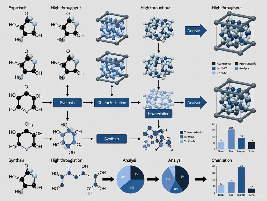
HTE Experimental Workflow and Data Flow
The diagram below illustrates the core HTE process and highlights the critical integration points necessary to overcome productivity challenges.
Frequently Asked Questions (FAQs)
Q1: What are the most common causes of failure in high-throughput drug discovery, and how can they be mitigated? A primary cause of failure is a lack of clinical efficacy (40-50% of failures), often stemming from inaccurate disease modeling and poor translation of results from models to human patients [4]. This can be mitigated by adopting more human-relevant models, such as induced Pluripotent Stem Cells (iPSCs), and applying Artificial Intelligence (AI) in the early screening and optimization phases to improve target identification and predict safety profiles more accurately [5].
Q2: How can I improve the precision of my experimental data and reduce wasteful repetition? Precision can be enhanced by implementing technologies that provide greater control and data granularity. In experimental contexts, this translates to techniques like variable rate technology, which uses sensors or pre-programmed maps to apply reagents or compounds at optimal rates rather than uniform concentrations, optimizing resource use [6]. Furthermore, machine section control can automatically turn application systems on or off for specific samples or wells that have already been treated, preventing duplicate application and reducing material waste [6].
Q3: A key objective is increasing the speed of our screening cycles. What approaches deliver the most significant time savings? Integrating AI and machine learning platforms can dramatically accelerate the initial drug candidate screening and design phases, a process that traditionally consumes significant time [5] [4]. For physical workflows, leveraging auto-guidance and fleet analytics principles—using real-time monitoring and automation to track equipment and optimize processes—can help increase asset utilization and decrease idle time, speeding up overall experimental throughput [6].
Q4: Our team struggles with knowledge transfer between projects, leading to repeated mistakes. How can we better capture and utilize experimental knowledge? Establish a centralized and searchable database for all experimental protocols, outcomes, and "failed" results. Framing experiments within a Structure–Tissue Exposure/Selectivity–Activity Relationship (STAR) framework ensures that key data on a compound's specificity, potency, and tissue exposure are systematically captured and can be analyzed to inform future candidate selection, avoiding repetition of past oversights [4].
Troubleshooting Guides
Issue: Inconsistent or Irreproducible Results in Cell-Based Assays
Symptoms: High well-to-well or plate-to-plate variability; inability to replicate previous findings.
Diagnosis and Resolution:
- Check Cell Line Health and Authenticity: Ensure cell lines are not contaminated (e.g., mycoplasma) and are correctly authenticated. Use early-passage cells.
- Verify Reagent Consistency: Use the same batches of critical reagents (e.g., serum, growth factors) within a single experimental series. Thaw reagents as single-use aliquots.
- Calibrate Equipment: Regularly calibrate liquid handlers, incubator COâ‚‚ levels, and plate readers. Confirm that pipettes are dispensing volumes accurately.
- Standardize Environmental Factors: Document and control for factors like passage number, confluency at time of assay, and precise timing of compound addition and reading.
Issue: High Attrition Rate of Lead Compounds in Later Validation Stages
Symptoms: Promising in-vitro candidates consistently fail in more complex disease models or due to toxicity.
Diagnosis and Resolution:
- Adopt a STAR Framework: Classify drug candidates early based on both potency/specificity (SAR) and tissue exposure/selectivity (STR). This helps identify Class II candidates (high potency but low tissue selectivity) that are prone to fail due to toxicity, allowing for earlier termination or redesign [4].
- Incorporate Human-Relevant Models: Supplement or replace traditional animal models with iPSC-derived human disease models where possible to better predict human responses and understand disease mechanisms earlier in the process [5].
- Expand Toxicity Screening: Beyond standard targets like hERG, utilize toxicogenomics and screen for accumulation in vital organs to identify potential toxicity liabilities before significant resources are invested [4].
Issue: Inefficient Use of Expensive Reagents and Materials
Symptoms: Frequent over-ordering of reagents; significant waste of costly materials.
Diagnosis and Resolution:
- Implement "Section Control": Apply the agricultural principle of machine section control to laboratory automation. Program liquid handlers and dispensers to only activate over designated sample wells, avoiding waste on empty wells or edge effects [6].
- Utilize Variable Rate Technology (VRT): Use data-driven approaches to determine the optimal amount of a reagent or compound for each experiment type, rather than applying a uniform, and often excessive, volume or concentration across all assays [6].
Quantitative Data on Research Efficiency
The following table summarizes quantitative benefits of precision approaches in a related field (agriculture), which serve as an analogy for the potential efficiency gains in high-throughput research environments [6].
Table 1: Measured Efficiency Gains from Precision Technologies
| Area of Impact | Current Adoption Benefit | Potential Benefit with Full Adoption |
|---|---|---|
| Fertilizer Placement Efficiency | 7% increase | Additional 14% efficiency gain |
| Herbicide/Pesticide Use | 9% reduction | Additional 15% reduction (48M lbs avoided) |
| Fossil Fuel Use | 6% reduction | Additional 16% reduction (100M gal saved) |
| Water Use | 4% reduction | Additional 21% reduction |
| Crop Production | 4% increase | Additional 6% productivity gain |
Experimental Protocol: Integrating iPSCs and AI for High-Throughput Target Validation
Objective: To efficiently validate a new molecular target for a neurodegenerative disease using a human-relevant model and computational pre-screening.
1. Materials and Reagents (The Scientist's Toolkit)
- Induced Pluripotent Stem Cells (iPSCs): Sourced from patients with the disease-causing mutation and healthy controls. Function: Provides a human-relevant disease model [5].
- Neural Differentiation Kit: A defined set of growth factors and media to direct iPSCs into the specific neural cell type of interest.
- AI-Based Screening Platform: (e.g., from Exscientia, Recursion, Schrödinger). Function: To computationally screen large compound libraries against the target structure, predicting high-affinity binders and potential off-target effects before physical testing [5] [4].
- High-Content Imaging System: An automated microscope for capturing phenotypic changes in differentiated neurons post-treatment.
- Multi-well Microplates: (e.g., 384-well) for high-throughput cell culture and compound treatment.
2. Methodology 1. AI-Powered In-Silico Screening: Use the AI platform to screen a virtual compound library. Select the top 100-200 predicted hits with high affinity for the target and low predicted toxicity for further testing. 2. iPSC Culture and Differentiation: Thaw and expand control and patient-derived iPSCs. Differentiate them into the relevant neural cells using the differentiation kit, following a standardized, high-throughput protocol in multi-well plates. 3. Compound Treatment: Treat the differentiated neurons with the hit compounds identified in Step 1. Include positive and negative controls on each plate. 4. Phenotypic and Viability Analysis: After a predetermined incubation period, use the high-content imaging system to quantify disease-relevant phenotypes (e.g., protein aggregation, neurite length) and cell viability. 5. Data Integration and STAR Analysis: Integrate the phenotypic data with the AI-predicted tissue exposure and selectivity profiles for each compound. Classify the lead candidates using the STAR framework to prioritize those with high potency and high tissue exposure/selectivity (Class I) for further development [4].
Workflow Visualization
Diagram 1: This workflow illustrates the integrated use of AI and iPSCs to increase the speed, scale, and precision of early target validation, directly addressing the core objectives.
Technical Support Center
Frequently Asked Questions (FAQs)
Q1: What are the most common symptoms of data fragmentation in a high-throughput lab? You may be experiencing data fragmentation if you notice researchers spending excessive time manually cleaning and organizing data, difficulty locating or combining datasets from different instruments, challenges in reproducing experiments, or inconsistencies in data analysis results across teams [7].
Q2: Our liquid handling robot seems to disconnect intermittently. What are the first steps I should take? Begin by isolating the source of the problem. Check if the disconnection stays with the same instrument regardless of the cable or USB port used [8]. Test communication with the instrument using native control software (like NI-MAX for VISA-controlled devices) to determine if the issue is with the instrument itself or the higher-level control software (e.g., LabVIEW) [8]. Ensure VISA resources are properly closed in your code after operations [8].
Q3: How can I improve the reproducibility of my high-throughput screening (HTS) assays? Automation is key to reducing inter- and intra-user variability [9]. Implement automated liquid handlers with integrated verification features, such as drop detection technology, to confirm dispensed volumes and standardize the workflow across all users and sessions [9].
Q4: What are the benefits of integrating my lab instruments with a centralized data platform? Centralized integration eliminates manual data transcription, reducing errors and ensuring data integrity [7]. It provides real-time data access for collaboration, enables full data traceability for compliance, and can optimize equipment utilization by tracking usage and maintenance needs [10].
Q5: Our research team struggles with different data formats from various spectrometers. What is the solution? A unified data management platform can solve this by standardizing data formats across all instruments. These platforms use APIs, serial connections, or file-based ingestion methods to automatically capture and standardize data from diverse equipment for straightforward analysis and reporting [10].
Troubleshooting Guides
Guide 1: Troubleshooting Instrument Disconnect Errors
Problem: A lab instrument (e.g., power supply, spectrometer) disconnects unexpectedly during an automated experiment and often requires a physical restart and software reboot to reconnect.
Scope: This guide applies to instruments connected via USB, Serial, or Ethernet that exhibit intermittent communication failures.
Diagnosis and Resolution Workflow: The following diagram outlines a systematic approach to diagnose and resolve persistent instrument disconnections.
Systematic Diagnosis Steps:
- Isolate the Hardware Component: As a first step, systematically switch the cables and USB/COM ports used for the malfunctioning instrument. If the disconnection problem consistently stays with the same physical instrument regardless of the cable or port, the issue is likely with the instrument itself [8].
- Test with Native Communication Tools: Use the instrument's native communication software (e.g., NI-MAX VISA control panel) to try and communicate with the device after a disconnect occurs. If the native tool can communicate but your primary control software (e.g., LabVIEW) cannot, the problem is likely a configuration or programming error in your control software and not the hardware [8].
- Inspect Control Software Code: Review the code in your automation software. A common programming error is the failure to properly close VISA sessions or other communication handles after operations are complete, which can lock the resource [8]. Also, check for logical errors in how the instrument is addressed and ensure all directories and COM port assignments are correct [8].
- Consider Alternative Connectivity: If the instrument supports it, consider using a more reliable communication bus. For instance, Ethernet with a fixed IP address is often more robust than USB, which can be prone to such disconnection issues [8].
Guide 2: Resolving Data Fragmentation and Management Bottlenecks
Problem: Data is siloed across multiple instruments and software systems, leading to slow retrieval, manual data handling errors, and inefficient analysis.
Scope: This guide addresses labs where data is manually transferred between instruments, spreadsheets, and databases.
Resolution Workflow: The path to a unified data management system involves evaluating your current state and implementing integration solutions.
Systematic Resolution Steps:
- Audit and Plan: List all instruments, the data formats they generate, and all current manual steps for data transfer and analysis [7]. Define the purpose and required outcomes for a centralized system [11].
- Select an Integration Method: Choose a method based on your instruments' capabilities [10]:
- Direct API Connection: For modern "smart" instruments that support REST or SOAP protocols. This allows for real-time, bidirectional data exchange.
- Serial/USB with Agent: For older instruments, use a local software agent to facilitate data transfer to the central platform.
- File-Based Ingestion: For instruments that generate data files, automate the process of reading files from a designated monitored folder.
- Implement a Centralized Platform: Adopt an HTE data management platform that supports the integration methods above. The platform should consolidate all experimental data into a single, structured system [7].
- Automate and Standardize: Use the platform to automate data capture and standardize data formats across all instruments. Implement automated work list generation for liquid handlers to minimize manual setup time and reduce errors [7].
Data and Solution Tables
Table 1: Impact of Data Fragmentation in Research
| Metric / Challenge | Impact of Fragmentation | Benefit of Centralized Data |
|---|---|---|
| Data Accuracy | Manual entry introduces transcription errors [7]. | Automated capture improves integrity and consistency [10]. |
| Experiment Throughput | Slow data retrieval and manual processing cause delays [7]. | Enables twice the experiment throughput due to faster workflows [7]. |
| Algorithm Accuracy | In healthcare, using data from a single center led to a 32.9% false-negative rate in identifying diabetic patients [12]. | A multi-center "gold standard" dataset significantly improves phenotyping accuracy [12]. |
| Operational Cost | Wasted resources and time on manual data management [7]. | Reduces costs by minimizing errors and resource use [9]. |
Table 2: Comparison of Instrument Connectivity Methods
| Method | Best For | Key Advantage | Key Consideration |
|---|---|---|---|
| Direct API | Modern, networkable instruments with API support [10]. | Most seamless, real-time, bidirectional communication [10]. | Requires instrument and network support. |
| Serial/USB with Agent | Older instruments with serial or USB output [10]. | Enables integration of legacy hardware; reliable data integration [10]. | Requires installation and maintenance of a local agent. |
| File-Based Ingestion | Any instrument that outputs data files [10]. | Highly versatile, no live connection to instrument needed [10]. | Introduces a slight delay compared to real-time methods. |
| Ethernet (Recommended) | Instruments with Ethernet ports [8]. | More reliable than USB; avoids disconnection issues; cheap to implement [8]. | Requires setup of a localized network with fixed IPs [8]. |
The Scientist's Toolkit: Essential Solutions for a Connected Lab
| Tool / Solution | Function in Overcoming Bottlenecks |
|---|---|
| HTE Data Management Platform | Centralizes data from all instruments, reducing fragmentation and providing instant data retrieval for analysis [7]. |
| Liquid Handler with Verification | Automates plate-based assays and uses technology (e.g., DropDetection) to verify dispensed volumes, enhancing reproducibility and reducing human error [9]. |
| Lab Digitalization Software | Provides the infrastructure (via APIs, agents, etc.) to seamlessly connect instruments, standardize data formats, and ensure full data traceability for compliance [10]. |
| API Integration Framework | Enables direct, real-time communication between "smart" instruments and the central data platform, eliminating manual data transfer [10]. |
| Automated Work List Generator | Creates work lists for liquid handling robots automatically, minimizing manual setup time and reducing errors in plate-based experiments [7]. |
| 3-Demethyl Thiocolchicine--13C2,d6 | 3-Demethyl Thiocolchicine--13C2,d6, MF:C21H23NO5S, MW:409.5 g/mol |
| [1-13Cgal]Lactose Monohydrate | [1-13Cgal]Lactose Monohydrate, MF:C12H24O12, MW:361.30 g/mol |
Technical Troubleshooting Guides
Data Fragmentation Across Multiple Instruments
Problem: My experimental data is scattered across different instruments (HPLC, mass spectrometers, liquid handlers), making it difficult to get a unified view.
Solution: Implement a centralized data management platform to consolidate information from all sources.
Methodology:
- Inventory all data-generating instruments in your workflow
- Establish standardized data formats for output from each instrument type
- Implement a centralized data repository with structured taxonomy
- Create automated data pipelines from instruments to the central system
- Validate data integrity through checksum verification and audit trails
Expected Outcome: 80% reduction in time spent organizing and verifying data across instruments [7]
Slow Manual Work List Creation
Problem: Manually creating work lists for liquid handling robots is time-consuming and prone to errors, slowing down my experimental throughput.
Solution: Automate work list generation using predefined templates and integration between experimental design software and liquid handlers.
Methodology:
- Map common experimental designs to liquid handler requirements
- Create standardized template libraries for different experiment types
- Implement API connectivity between experimental design software and liquid handler control systems
- Validate automated work lists with control experiments before full implementation
- Establish version control for all work list templates
Expected Outcome: Elimination of manual entry errors and 75% reduction in experiment setup time [7]
Delayed Data Analysis Due to Processing Bottlenecks
Problem: After experiments conclude, it takes too long to retrieve and process data for analysis, delaying critical decisions.
Solution: Implement automated data retrieval and preprocessing pipelines with real-time analysis capabilities.
Methodology:
- Identify key analysis parameters and output requirements
- Develop automated data transformation scripts for raw data conversion
- Implement triggered analysis workflows that automatically process data upon experiment completion
- Create dashboard visualizations for immediate result interpretation
- Set up alert systems for predefined significance thresholds
Expected Outcome: Instant access to processed results enabling iterative experiments 50% faster [7]
Data Management Framework
Quantitative Comparison of Data Management Approaches
Table: Data Management Strategy Performance Metrics
| Management Approach | Implementation Time | Data Retrieval Speed | Error Reduction | IT Dependency |
|---|---|---|---|---|
| Centralized Platform | 4-6 weeks | Real-time | 80% | Low after setup |
| Manual Integration | Immediate | 2-4 hours | 0% | High |
| Basic Automation | 2-3 weeks | 15-30 minutes | 45% | Medium |
| Advanced AI Pipeline | 8-12 weeks | Near real-time | 90% | Medium-high |
Table: Cognitive Load Impact of Different Information Presentation Methods
| Presentation Method | Decision Speed | Error Rate | Cognitive Fatigue | Best Use Case |
|---|---|---|---|---|
| Raw Data Tables | Slow | High | High | Data validation |
| Basic Charts | Medium | Medium | Medium | Team meetings |
| Interactive Dashboards | Fast | Low | Low | Rapid response |
| Prioritized Alerts | Very Fast | Very Low | Very Low | Critical decisions |
Experimental Protocol: Implementing Cognitive Offloading
Purpose: To systematically reduce mental workload for researchers through external tools, improving decision accuracy in data-rich environments.
Materials:
- Decision-support dashboard software
- Automated reporting tools
- Predefined analysis playbooks
- Alert and notification system
Procedure:
- Identify repetitive decision points in your experimental workflow
- Map data requirements for each decision point
- Configure automated data feeds to decision-support tools
- Establish threshold-based alerts for abnormal patterns
- Validate system recommendations against expert judgment
- Iteratively refine automation rules based on performance
Validation Metric: 40% reduction in time spent on routine data interpretation tasks without sacrificing accuracy [13]
Data Processing Workflow
Title: High-Throughput Data Processing Workflow
Frequently Asked Questions (FAQs)
What exactly is a "data deluge" in high-throughput experimentation?
A data deluge occurs when the volume of data generated exceeds an organization's capacity to manage, analyze, or use it effectively. In high-throughput labs, this typically manifests when multiple parallel experiments generate terabytes of data daily from various instruments, overwhelming traditional analysis methods and storage systems [14].
How can we quickly determine which data to prioritize when overwhelmed?
Apply the Pareto Principle (80/20 Rule): focus on the 20% of data that will deliver 80% of your insights. Implement these steps:
- Identify Key Risk Indicators specific to your experimental goals
- Use intuitive triage systems to separate high-priority signals from background noise
- Implement structured playbooks to streamline response processes
- Establish data filtration criteria before experiments begin [13]
What are the most common pitfalls in managing data from parallel experiments?
- Collecting excessive data without clear objectives increases storage costs and complexity
- IT-driven data governance bottlenecks that slow down data accessibility for researchers
- Tool limitations in handling unstructured data like machine logs and sensor outputs
- Insufficient data organization before implementing enterprise applications [14]
How can we improve team decision-making under data overload conditions?
- Implement cognitive offloading through decision-support dashboards
- Apply Hick's Law by reducing choices to speed decision-making
- Use "chunking" techniques to break information into manageable pieces
- Train with deliberate practice using realistic simulations [13]
- Establish clear data visualization standards that highlight trends rather than raw data
Research Reagent Solutions
Table: Essential Research Reagents for High-Throughput Experimentation
| Reagent/Tool | Function | Implementation Consideration |
|---|---|---|
| HTE Data Management Platform | Centralizes and structures experimental data | Requires 4-6 week implementation; reduces manual entry by 80% [7] |
| Liquid Handling Robot Automation | Automates work list generation and sample preparation | Eliminates manual entry errors; requires template standardization |
| API Integration Framework | Enables seamless data transfer between instruments | Needs compatibility mapping; enables real-time data availability |
| Cognitive Offloading Tools | Reduces mental workload through external aids | Improves decision accuracy by 40% in data-rich environments [13] |
| Automated Analysis Pipelines | Processes data automatically upon experiment completion | Enables instant access to results; accelerates discovery timelines |
Information Prioritization Framework
Title: Information Filtration and Prioritization System
Ensuring Accuracy and Reproducibility at Microscale
In the drive to enhance productivity within high-throughput experimentation (HTE), particularly in fields like drug development, ensuring the accuracy and reproducibility of results is not just a best practice—it is a fundamental requirement. The ability to consistently reproduce scientific findings forms the bedrock of reliable innovation and efficient research workflows. However, microscale techniques, despite their advantages in low sample consumption and speed, present unique challenges that can threaten the integrity of data if not properly managed. As highlighted by a major multi-laboratory benchmark study, even established biophysical methods like Microscale Thermophoresis (MST) require rigorous standardization and a deep understanding of their underlying principles to be reliably deployed across different instruments and labs [15] [16]. This technical support center is designed to help researchers, scientists, and drug development professionals overcome these specific hurdles. By providing clear troubleshooting guides, detailed protocols, and curated FAQs, we aim to fortify your experimental processes, minimize costly repeats, and ultimately accelerate the pace of discovery in high-throughput research.
Understanding Reproducibility in Microscale Science
Key Definitions and a Framework for Validation
A precise understanding of key terms is crucial for diagnosing and solving reproducibility issues. The following framework, adapted from the broader microbial sciences, helps categorize and address different types of validation [17].
The table below outlines the core concepts of scientific validation:
| Term | Definition | Example in Microscale Work |
|---|---|---|
| Reproducibility | The ability to regenerate a result using the same dataset and analysis workflow. | Re-analyzing the same raw MST data file on the same software and obtaining the same dissociation constant (KD). |
| Replicability | The ability to produce a consistent result with an independent experiment asking the same scientific question. | Performing a new MST titration with freshly prepared samples of the same protein-ligand pair and confirming the KD. |
| Robustness | The ability to obtain a consistent result using different methods within the same experimental system. | Confirming an MST-derived KD for a protein interaction using a different technique like Isothermal Titration Calorimetry (ITC) on the same samples. |
| Generalizability | The ability to produce a consistent result across different experimental systems (e.g., different cell lines, model organisms). | A drug-target interaction identified via MST in a recombinant system also showing efficacy in a cell-based assay and an animal model. |
Most research aims for results that are not only reproducible but also replicable, robust, and generalizable. Threats to these goals can be technical, biological, or analytical in nature [17].
The Instrumentation Challenge: A Case Study on MST
Microscale Thermophoresis (MST) is a powerful technique for quantifying biomolecular interactions. However, a large, independent benchmark study involving 32 scientific groups and 40 instruments revealed specific sources of variability that can compromise reproducibility [15] [16]. The study identified that the reliability of MST/TRIC (Temperature Related Intensity Change) can be affected by:
- Signal Complexity: The measured signal is a composite of thermophoresis, temperature-related intensity changes, and other effects that are not fully understood, making data interpretation sensitive to analysis methods [15].
- Hardware and Software Variability: Differences between instrument generations and changes in data analysis software over time can introduce variability [15].
- Experimenter Influence: The benchmark found that the choices made by the scientist during data analysis were a significant factor in the dispersion of final results [15].
This underscores that reproducibility is not an inherent property of an instrument but is achieved through rigorous standardization of the entire experimental and analytical process.
Troubleshooting Guides and FAQs
This section addresses common, specific issues encountered in microscale experiments, with a focus on MST.
Frequently Asked Questions (FAQs)
Q1: My MST data shows a high signal-to-noise ratio. What are the most likely causes? A: A noisy signal can stem from several factors:
- Fluorescent Impurities: Particulates or aggregated protein in the sample can cause significant light scattering and noise. Always centrifuge your samples briefly before loading capillaries.
- Inadequate Labeling: A low degree of labeling (DOL) can result in a weak signal from the labeled target molecule, which is easily overwhelmed by background noise. Ensure your DOL is within the recommended range (typically 0.5-1.5 for the RED dye).
- Capillary Quality: Scratched or dirty capillaries can distort the laser path and detection. Use premium quality, coated capillaries and inspect them before use.
Q2: During a binding experiment, my dose-response curve has a poor fit. How can I improve it? A: A poorly fitted curve often indicates issues with the experimental setup or compound properties:
- Non-Monotonic Behavior: This can occur if the ligand itself absorbs or fluoresces at the detection wavelength (inner filter effect), or if the binding event induces conformational changes that affect fluorescence in complex ways. Include ligand-only control measurements to correct for this.
- Incorrect Concentration: An inaccurate concentration of the titrated molecule is a common culprit. Use multiple, precise methods (e.g., absorbance, amino acid analysis) to confirm concentrations, especially for proteins [15].
- Evaporation: For long measurements, evaporation from the capillaries can alter concentrations. Ensure consistent environmental conditions and use sealed capillaries if necessary.
- Buffer Composition: Subtle differences in pH, salt concentration, or the presence/absence of additives like Tween-20 can dramatically affect binding. Precisely replicate the buffer system.
- Sample Quality and Handling: Confirm the integrity and monodispersity of your proteins via SDS-PAGE and size-exclusion chromatography. Avoid repeated freeze-thaw cycles.
- Temperature: MST is highly temperature-sensitive. Ensure the instrument temperature is stable and set correctly.
- Data Analysis Parameters: Adhere strictly to a Standard Operating Procedure (SOP) for data analysis. The benchmark study showed that the experimenter's choices during analysis are a major source of variability [15].
Troubleshooting Common MST/TRIC Issues
The following table summarizes specific problems, their potential causes, and solutions.
| Problem | Potential Causes | Solutions and Checks |
|---|---|---|
| Low Fluorescence | 1. Low degree of labeling (DOL).2. Fluorophore quenching.3. Protein concentration too low. | 1. Measure DOL spectrophotometrically; repeat labeling if necessary.2. Check for buffer components that may quench the dye (e.g., certain reducing agents).3. Increase protein concentration while ensuring it remains in the linear detection range. |
| High Signal Noise | 1. Particulates in the sample.2. Protein aggregation.3. Dirty or defective capillaries. | 1. Centrifuge samples at high speed (e.g., 15,000 x g) for 10 minutes before measurement.2. Analyze protein via dynamic light scattering or SEC; use stabilizing agents in buffer.3. Use new, premium coated capillaries; ensure they are clean and undamaged. |
| Poor Curve Fit / Unusual Shape | 1. Ligand fluorescence/absorption (inner filter effect).2. Protein degradation during experiment.3. Inaccurate concentration of binding partner. | 1. Include a ligand-only control and use it for correction in the analysis software.2. Keep samples on ice during preparation; limit experiment duration.3. Use a highly precise method (e.g., quantitative amino acid analysis) to verify concentration [15]. |
| Irreproducible KD between replicates | 1. Pipetting inaccuracies during serial dilution.2. Inconsistent sample preparation.3. Instrument performance drift. | 1. Use calibrated pipettes and perform reverse titrations to check for pipetting errors.2. Prepare a master mix of the labeled molecule for all replicates.3. Perform regular instrument performance checks with a standard dye (e.g., RED dye) to monitor laser and detector stability [15]. |
Standardized Experimental Protocols
Adherence to detailed, standardized protocols is the most effective way to ensure reproducibility across experiments and laboratories. The following protocol for a protein-small molecule interaction study via MST is adapted from the ARBRE-MOBIEU benchmark study, which established high reproducibility across dozens of labs [15].
Detailed Protocol: Protein-Small Molecule Interaction via MST
Objective: To accurately determine the dissociation constant (KD) for the interaction between Hen Egg Lysozyme and N,N',N''-Triacetylchitotriose (NAG3) using MST.
Materials (Research Reagent Solutions):
- Lysozyme: Isolated from hen egg white.
- RED-NHS 2nd Generation Dye: Amine-reactive fluorescent label (NanoTemper Technologies).
- NAG3: The small molecule ligand.
- Labeling Buffer: As supplied in the Monolith NT Protein Labeling Kit.
- MST/TRIC Assay Buffer: 20 mM Tris pH 7.8, 150 mM NaCl, 0.005% Tween-20.
- DMSO: Molecular biology grade.
- Gravity Flow Columns: For purification of labeled protein (e.g., from the Monolith NT Protein Labeling Kit).
- Premium Coated Capilleries: (e.g., NanoTemper MO-K025).
Methodology:
Labeling of Lysozyme:
- Prepare a ~700 µM stock solution of lysozyme in PBS buffer.
- Resuspend the RED-NHS 2nd generation dye in DMSO to create a ~600 µM stock.
- Mix 100 µL of 20 µM lysozyme (in labeling buffer) with 100 µL of 60 µM dye solution (in labeling buffer). The final reaction volume is 200 µL with 5% DMSO.
- Incubate the reaction for 30 minutes at room temperature in the dark.
Purification of Labeled Protein:
- Equilibrate a gravity flow column with the MST/TRIC assay buffer (Tris+). Wash three times with 3 mL of buffer.
- Apply the 200 µL labeling reaction to the column. After it enters the bed, add 500 µL of assay buffer and discard the flow-through.
- Transfer the column to a new collection tube and elute the labeled protein with 400 µL of assay buffer.
- Determine the concentration and Degree of Labeling (DOL) of the purified lysozyme by absorbance at 280 nm and the dye's absorbance at its peak (e.g., ~650 nm for RED dye), applying the necessary correction factors. The final concentration should be adjusted to ~50 nM for the experiment. Aliquot and freeze if not used immediately.
Sample Preparation for MST:
- Prepare a 2 mM stock solution of NAG3 in the MST/TRIC assay buffer.
- Perform a 1:1 serial dilution of NAG3 in the same buffer to create 16 concentrations, typically spanning a range from above the expected KD to well below it.
- Mix a constant volume of the labeled lysozyme (final concentration e.g., 50 nM) with each concentration of the NAG3 dilution series. Use the same buffer to balance volumes. The final volume for each point should be sufficient to load an MST capillary (typically 5-10 µL).
MST Measurement:
- Load each sample into a premium coated capillary.
- Place the capillaries in the Monolith instrument.
- Instrument Settings: Follow a strict SOP. The benchmark study used defined settings for laser power (e.g., 20-40%) and MST power (e.g., Medium or High) based on the signal strength. The use of the red filter set was mandatory. All measurements should be performed at a consistent temperature (e.g., 25°C).
Data Analysis:
- Analyze the data using the recommended software (e.g., MO.Affinity Analysis).
- Use the same parameters for all datasets. The benchmark study highlighted that normalizing the fluorescence (F Norm) to the initial value (F Initial) was a key step.
- Fit the data to a suitable binding model (e.g., KD model) to obtain the dissociation constant.
The workflow for this standardized protocol can be visualized as follows:
The Scientist's Toolkit: Essential Research Reagents and Materials
The following table details key reagents and materials used in the featured MST experiment, along with their critical functions for ensuring accuracy.
| Item | Function / Role in Experiment | Key Consideration for Reproducibility |
|---|---|---|
| RED-NHS 2nd Generation Dye | Fluorescent label that covalently binds to amine groups on the protein, enabling detection in the MST instrument. | Consistent dye purity and reactivity between batches is critical. Aliquot the dye stock to avoid repeated freeze-thaw cycles. |
| Premium Coated Capillaries (MO-K025) | Transparent vessels that hold the sample for measurement. The coating reduces surface interactions. | Using the same high-quality, coated capillaries minimizes protein adhesion and ensures consistent laser path geometry, reducing variability. |
| Labeling Buffer (from Kit) | Optimized chemical environment for the dye-protein conjugation reaction. | Using the manufacturer's recommended buffer ensures optimal labeling efficiency and consistency. |
| Gravity Flow Columns | Size-exclusion chromatography columns that separate labeled protein from free, unreacted dye. | Consistent packing and performance of these columns are essential for obtaining a pure labeled protein sample with a defined DOL. |
| Tween-20 | Non-ionic detergent added to the assay buffer. | Prevents non-specific binding of the protein to surfaces (e.g., capillaries, tube walls), a common source of loss and inconsistency. A standard concentration of 0.005% was used in the benchmark [15]. |
| Standardized Lysozyme/NAG3 | The well-characterized model interaction system used for validation. | Using a central, aliquoted stock of both protein and ligand, as done in the benchmark study, eliminates variability arising from sample preparation and is key for inter-lab reproducibility [15]. |
| 7(R)-7,8-Dihydrosinomenine | 7(R)-7,8-Dihydrosinomenine|RUO | 7(R)-7,8-Dihydrosinomenine is a high-purity analytical standard for research use only (RUO). It supports studies in natural product chemistry and pharmacology. |
| Phenethyl acetate-13C2 | Phenethyl acetate-13C2, MF:C10H12O2, MW:166.19 g/mol | Chemical Reagent |
Visualizing the Path to Reproducibility
Achieving reproducibility is a systematic process that extends beyond the bench. The following diagram outlines a holistic workflow, from initial planning to final response to data, integrating the principles discussed in this guide.
Spatial Bias and Environmental Control in Miniaturized Formats
FREQUENTLY ASKED QUESTIONS (FAQS)
FAQ 1: What is spatial bias and why is it a critical issue in High-Throughput Screening (HTS)?
Spatial bias is a systematic error that negatively impacts experimental high-throughput screens, leading to over or under-estimation of true signals in specific well locations, rows, or columns within microplates. Various sources of bias include reagent evaporation, cell decay, errors in liquid handling, pipette malfunctioning, variation in incubation time, time drift in measuring different wells or different plates, and reader effects. This bias produces row or column effects, particularly on plate edges, and can lead to increased false positive and false negative rates during the hit identification process, ultimately increasing the length and cost of the drug discovery process [18].
FAQ 2: What is the difference between additive and multiplicative spatial bias?
Spatial bias in high-throughput screening can follow two primary models. Additive bias involves a constant value being added or subtracted from measurements, regardless of the actual signal intensity. By contrast, multiplicative bias involves the measurement being multiplied by a factor, meaning the bias effect scales with the signal intensity itself. Research shows that screening data can be affected by either type, and each requires specific statistical methods for effective correction [18] [19].
FAQ 3: How do miniaturized formats (e.g., 384-well, 1536-well plates) exacerbate environmental control issues?
The drive to reduce costs and increase throughput has led to progressive assay miniaturization. However, smaller volumes are more susceptible to evaporation and edge effects, where thermal gradients or differential evaporation rates across a microplate cause inconsistent cell growth or assay performance in peripheral wells. Lower cell numbers per well can also decrease signal intensity, demanding more sensitive detection systems [20] [21].
FAQ 4: What are the best practices for mitigating edge effects in miniaturized assays?
Strategic plate design and procedural adjustments are key. Mitigation strategies include either omitting data from edge wells (which reduces throughput and increases cost) or implementing procedural adjustments like pre-incubating plates at room temperature after seeding to allow for thermal equilibration. The strategic placement of positive and negative controls on each assay plate is also critical for monitoring assay performance and identifying these systematic errors [20].
TROUBLESHOOTING GUIDES
Problem 1: High False Positive/Negative Rates Due to Spatial Bias
Description: Hit selection is unreliable due to systematic spatial errors across plates.
Investigation & Diagnosis:
- Step 1: Visually inspect raw data heatmaps for clear row, column, or edge patterns.
- Step 2: Statistically confirm the presence and model of the bias (additive vs. multiplicative) using tests like the Mann-Whitney U test or Kolmogorov-Smirnov two-sample test [18].
- Step 3: Determine if the bias is assay-specific (appears across all plates in an assay) or plate-specific (unique to individual plates) [18].
Resolution:
- Action 1: For plate-specific spatial bias, apply a dedicated bias correction algorithm.
- Action 2: For assay-specific spatial bias (systematic error from specific well locations), apply Well Correction or normalization using robust Z-scores [18].
- Action 3: A recommended protocol is to first correct for plate-specific bias (using the appropriate additive or multiplicative model), followed by assay-wide normalization using robust Z-scores. Studies show this combined approach yields higher hit detection rates and lower false positive and false negative counts compared to using either method alone [18].
Problem 2: Data Inconsistency and Poor Reproducibility Across Plates
Description: Results are inconsistent between plates within a run or across different screening days.
Investigation & Diagnosis:
- Step 1: Check key Quality Control (QC) metrics like Z'-factor across plates to quantify the assay robustness and signal-to-noise ratio [20].
- Step 2: Verify the consistency of liquid handling systems for calibration and performance.
- Step 3: Monitor environmental factors such as laboratory temperature and humidity, which can drift over time.
Resolution:
- Action 1: Ensure rigorous assay validation before a full screen, demonstrating pharmacological relevance and reproducibility under screening conditions [20].
- Action 2: Implement a robust system of positive and negative controls on every plate to enable data normalization and continuous performance monitoring [20].
- Action 3: Integrate data management solutions that automate data capture from instruments, standardize formats, and facilitate streamlined analysis to reduce human error and improve consistency [20] [22].
Problem 3: Evaporation and Edge Effects in High-Density Plates
Description: Assay performance is degraded in peripheral wells, especially in 384-well and 1536-well formats.
Investigation & Diagnosis:
- Step 1: Review heatmaps of control wells to identify a specific pattern of signal drift on the edges of the plate.
- Step 2: Confirm that environmental controls in incubators and automated systems are functioning correctly.
Resolution:
- Action 1: Use microplates specifically designed for miniaturization, such as 384-well Small Volume microplates or half-area plates, which can help manage meniscus and evaporation [21].
- Action 2: For manual workflows where moving to a 384-well plate is impractical, consider 96-well Half Area microplates to reduce volumes by up to 50% while maintaining compatibility with standard lab equipment [21].
- Action 3: Ensure proper environmental control within automated systems and incubators to minimize thermal gradients and evaporation differentials [20].
EXPERIMENTAL PROTOCOLS
Protocol 1: Detecting and Correcting Spatial Bias
Methodology: This integrated protocol detects and corrects for both assay-specific and plate-specific spatial biases.
- Step 1: Data Preparation. Organize raw measurement data from HTS run, ensuring it is mapped to well locations (e.g., A01, B01) and plate identifiers.
- Step 2: Bias Detection.
- Generate plate-wise heatmaps of raw data to visualize potential spatial patterns.
- Perform statistical testing (e.g., Mann-Whitney U test, Kolmogorov-Smirnov test) on rows and columns to determine if bias is present and statistically significant. A significance threshold (e.g., α=0.01 or α=0.05) is applied [18].
- Classify the bias as additive or multiplicative based on the data distribution and relationship to signal intensity [18] [19].
- Step 3: Bias Correction.
- Step 4: Hit Identification. Select hits from the corrected data using a threshold, typically the plate mean minus three standard deviations (μp − 3σp) [18].
The workflow for this protocol is outlined in the following diagram:
Protocol 2: Quality Control for Miniaturized HTS Assays
Methodology: A procedure to establish and monitor key quality metrics for miniaturized formats.
- Step 1: Plate Design. Strategically distribute positive and negative controls across the plate, including on the edges, to monitor spatial bias.
- Step 2: Calculate QC Metrics. For each plate, calculate the Z'-factor, a standard metric for assessing assay quality and robustness based on control well data [20].
- Step 3: Outlier Detection. Employ statistical methods like the Grubb's test or SSMD (Strictly Standardized Mean Difference) to identify and handle outlier wells that could skew results [20].
- Step 4: Continuous Monitoring. Track QC metrics across all plates and screening runs to identify drifts in performance over time.
DATA AND METHODOLOGY COMPARISON
Table 1: Performance Comparison of Spatial Bias Correction Methods
This table summarizes simulated data comparing the effectiveness of different bias correction methods in HTS. The results demonstrate that a combined approach (PMP + robust Z-scores) outperforms others by achieving a higher true positive rate and lower total errors (false positives + false negatives) [18].
| Correction Method | Handles Additive Bias? | Handles Multiplicative Bias? | Average True Positive Rate (at 1% Hit Rate) | Average Total False Positives & Negatives (per assay) |
|---|---|---|---|---|
| No Correction | No | No | Low | High |
| B-score Only | Yes | No | Medium | Medium |
| Well Correction (Assay-specific) | Yes | Limited | Medium | Medium |
| PMP + Robust Z-scores | Yes | Yes | Highest | Lowest |
Table 2: Microplate Format Comparison for Miniaturized HTS
This table compares common microplate formats used in HTS, highlighting the trade-offs between throughput, volume, and susceptibility to spatial effects [21].
| Microplate Format | Typical Working Volume | Growth Area (per well) | Key Considerations |
|---|---|---|---|
| 96-well | 50-200 µl | ~32 mm² | Standard, easy to handle, lower throughput. |
| 96-well Half Area | 25-100 µl | ~15 mm² | 50% volume reduction, compatible with standard equipment. |
| 384-well | 10-50 µl | ~12 mm² | High throughput, more susceptible to edge/evaporation effects. |
| 384-well Small Volume | 4-25 µl | ~2.7 mm² | Significant reagent savings, requires careful liquid handling. |
| 1536-well | 1-10 µl | ~2.2 mm² | Ultra-high throughput, highly susceptible to environmental bias. |
THE SCIENTIST'S TOOLKIT: KEY RESEARCH REAGENT SOLUTIONS
Table 3: Essential Materials for Managing Spatial Bias
| Item | Function & Relevance |
|---|---|
| 384-Well Small Volume Microplates | Specialized plates with reduced well volume and growth area to minimize reagent usage while maintaining compatibility with standard readers. Ideal for top and bottom reading at low volumes [21]. |
| Cycloolefin (COP/COC) Storage Plates | Plates made from chemically resistant cycloolefin polymers with excellent acoustic liquid handling properties. Low water absorption and high transparency make them ideal for compound management and direct transfer protocols, reducing dead volume [21]. |
| AssayCorrector Software | An R package available on CRAN, specifically designed to detect and remove both additive and multiplicative spatial bias from HTS/HCS data [19]. |
| phactor Software | A software tool (free for academic use) that facilitates the design, performance, and analysis of HTE in 24-, 96-, 384-, or 1,536-well plates. It helps manage the logistical load and data integration challenges of miniaturized screens [22]. |
| Acoustic Liquid Handlers | Non-contact liquid handling systems that use sound energy to transfer nanoliter volumes. They eliminate cross-contamination and are key for precise dispensing in miniaturized direct compound transfer protocols [20] [21]. |
| 6-Azido-N-acetylgalactosamine-UDP | 6-Azido-N-acetylgalactosamine-UDP, MF:C17H26N6O16P2, MW:632.4 g/mol |
| Acetyl heptapeptide-4 | Acetyl heptapeptide-4, CAS:1459206-66-6, MF:C37H64N14O14S, MW:961.1 g/mol |
Modern HTE Workflows: Integrating Automation, AI, and Advanced Technologies
In high-throughput experimentation (HTE) research, automated laboratory systems are pivotal for accelerating drug discovery and process development. However, these systems can introduce significant productivity challenges when they fail or perform suboptimally. Issues with robotic liquid handlers, in particular, can compromise data integrity, lead to costly reagent loss, and create substantial downtime [1] [23]. This technical support center provides targeted troubleshooting guides and FAQs to help researchers maintain peak operational efficiency and data reliability in their automated workflows.
Troubleshooting Guides
Common Liquid Handling Robot Problems and Solutions
Liquid handling robots (LHRs) are prone to specific, recurring issues. The table below summarizes these problems and how to mitigate them.
Table 1: Common Liquid Handling Robot Problems and Mitigation Strategies
| Observed Problem | Possible Source of Error | Specific Troubleshooting Techniques & Solutions |
|---|---|---|
| Incorrect aspirated volume; dripping tip [24] [25] | Leaky piston/cylinder; difference in vapor pressure of sample vs. water [24]. | Regularly maintain system pumps and fluid lines [24]. Sufficiently prewet tips or add an air gap after aspiration [24]. |
| Droplets or trailing liquid during delivery [24] [25] | Liquid characteristics (e.g., viscosity) differ from water [24]; Reagent residue build-up [25]. | Adjust aspirate/dispense speed; add air gaps or blowouts [24]. Clean permanent tips regularly; select appropriate tip type for the liquid [25]. |
| Serial dilution volumes varying from expected concentration [24] [23] | Insufficient mixing in the wells before the next transfer [24]. | Measure and optimize liquid mixing efficiency [24]. Validate that wells are homogenously mixed before the next transfer step [23]. |
| First or last dispense volume difference in sequential dispensing [24] [23] | Inherent to the sequential dispense method [24]. | Dispense the first or last quantity into a reservoir or waste [24]. Validate that the same volume is dispensed in each successive transfer [23]. |
| Diluted liquid with each successive transfer [24] | System liquid is in contact with the sample [24]. | Adjust the leading air gap [24]. |
| Contamination or carryover [25] [23] | Ineffective tip washing for fixed tips; residual liquid in disposable tips [23]; droplets falling from tips during movement [23]. | Implement rigorous tip-washing validation protocols for fixed tips [23]. Use vendor-approved disposable tips [23]. For sequential steps, ensure adequate cleaning between transfers [25]. Add a trailing air gap after aspiration [23]. |
System Integration and Pre-Flight Checks
Many operational errors stem from incorrect setup rather than mechanical failure. Integrating your LHR with a Laboratory Information Management System (LIMS) can prevent these issues [26].
The most robust integration pattern combines three approaches to ensure the virtual experiment in the LIMS matches the physical one on the robot deck [26]:
- Pattern 1: The LIMS produces a "driver file" for the LHR to consume.
- Pattern 3: The LHR performs a "pre-flight check" before starting, verifying that the correct containers are in the correct deck positions and that reagents are not expired.
- Pattern 2: After the run, the LIMS consumes a log file from the LHR to record what actually happened, including any failed transfers [26].
This integrated workflow ensures errors are caught before they can affect an entire experiment.
Diagnostic Workflow for Liquid Handler Variability
Follow this logical troubleshooting sequence to diagnose the source of liquid handler variability.
Frequently Asked Questions (FAQs)
1. How can I verify that my liquid handler is dispensing accurate volumes? Regular performance verification is critical. Two common methods are:
- Gravimetric Measurement: Weighing the dispensed liquid to verify the correct volume has been transferred. This is highly accurate but may not be performed in the actual labware.
- Photometric Measurement: Using a dye and measuring its fluorescence to verify volume. This method allows for testing directly in the labware used for experiments [25]. It is recommended to implement a standardized, regular calibration program [23].
2. What is the most effective way to prevent contamination in automated liquid handlers? Contamination can be prevented through several best practices:
- For disposable tips, always use vendor-approved tips to ensure quality and fit, and plan tip ejection locations carefully [23].
- For permanent tips, implement and validate rigorous tip-washing protocols to ensure no residual reagent remains [25] [23].
- Adjust pipetting parameters: using a trailing air gap after aspiration can minimize liquid slipping from the tip [23].
3. Our high-throughput experimentation generates too much data to manage efficiently. How can automation help? Informatics platforms are a key part of lab automation. Solutions like a Laboratory Information Management System (LIMS) can automate data capture, traceability, and reporting. By integrating systems end-to-end, these platforms eliminate manual data transcription, which can consume over 75% of a scientist's time, thereby accelerating decision-making [1] [27].
4. What are the economic impacts of liquid handling errors? Errors can have severe financial consequences:
- Over-dispensing expensive or rare reagents can cost hundreds of thousands of dollars per year in lost materials [23].
- Inaccurate dispensing can compromise assay results, leading to false positives or false negatives. A false negative could cause a promising drug candidate to be overlooked, potentially costing a company billions in future revenue [23].
5. What routine maintenance is essential for automated liquid handlers? Regular maintenance is required for consistent, reliable results [25]:
- Inspection: Routinely check for wear and tear, such as kinks in tubing, loose fittings, or obstructions to moving parts.
- Cleaning: Clean permanent pipette tips regularly to prevent reagent build-up.
- Performance Monitoring: Use gravimetric or photometric methods to regularly check dispensing accuracy.
- Part Replacement: Replace components like tubes, valves, and pumps as needed to prevent costly repairs [25].
The Scientist's Toolkit: Key Research Reagent Solutions
The following table details essential materials and their functions critical for successful and reliable automated liquid handling.
Table 2: Essential Materials for Automated Liquid Handling
| Item | Function & Importance |
|---|---|
| Vendor-Approved Pipette Tips | Ensures accuracy and precision. Off-brand tips may have variable manufacturing quality (e.g., flash, poor fit), leading to delivery errors [23]. |
| Appropriate Liquid Class Settings | Software-defined parameters (aspirate/dispense rates, heights) tailored to liquid properties (viscosity, surface tension). Using incorrect settings is a major source of error [23]. |
| Calibration Standards (Gravimetric/Photometric) | Used for regular performance verification of liquid handlers to ensure they are dispensing volumes within specification [25] [23]. |
| Assay-Ready Plates & Labware | High-quality microplates with consistent well dimensions and properties are essential for accurate optical readings and liquid tracking. |
| LIMS (Laboratory Information Management System) | Manages sample data, workflow tracking, and integration with automated instruments, providing data integrity and traceability from cradle-to-cradle [1] [26]. |
| Kaempferol-3-O-robinoside-7-O-glucoside | Kaempferol-3-O-robinoside-7-O-glucoside, MF:C33H40O20, MW:756.7 g/mol |
| 2,5-Diethyl-3-methylpyrazine-d3 | 2,5-Diethyl-3-methylpyrazine-d3 Stable Isotope |
Workflow for Integrating a Liquid Handler with a LIMS
Implementing the following workflow, which combines multiple integration patterns, is the current best practice for minimizing common LHR problems.
Centralized Data Management Platforms for Unified Experimental Data
Troubleshooting Guides
Data Integration and Collection Issues
Problem: "Request Timed Out" or "Session Remote Host Unknown" errors during data collection.
- Cause: These errors typically indicate network connectivity issues, incorrect credentials, or the monitored device/application being unable to respond within the expected time [28].
- Solution:
- Verify the device is reachable on the network.
- Confirm the correct credentials, community names (for SNMP), or access rights are configured [28].
- For SNMP timeouts, create a new credential profile with an increased timeout value [28].
- Ensure the required ports are open and available on the target device [28].
Problem: "Access is Denied" when connecting to a data source.
- Cause: Incorrect login credentials or the user account lacks sufficient privileges for remote data access [28].
- Solution:
- For domain-joined devices, ensure the username is formatted as
domainname\usernameand the password is correct [28]. - Verify that the user account belongs to the Administrator group on the target machine or has been explicitly granted remote access privileges [28].
- Confirm that 'Remote DCOM' is enabled on the monitored device for WMI connections [28].
- For domain-joined devices, ensure the username is formatted as
Problem: "Null variable in response" or "No such object in this MIB."
- Cause: The Management Information Base (MIB) or specific Object Identifier (OID) you are trying to query is not supported or implemented on the target device [28].
- Solution:
Data Quality and Governance Issues
Problem: Data inconsistencies and duplication across different experimental systems.
- Cause: Data silos, where information is isolated in different departments or systems with varying formats and standards, lead to fragmentation [29] [30].
- Solution:
- Implement a centralized data warehouse or platform to consolidate data from multiple sources into a single source of truth [29] [31].
- Establish and enforce data governance frameworks with clear data quality standards and ownership [29] [32].
- Utilize data validation processes and automated error checks at the point of data entry to minimize errors [32].
Problem: Difficulty tracking data lineage and ensuring compliance.
- Cause: A fragmented data environment makes it complex to trace the origin and modifications of data, which is critical for audit trails and regulatory compliance (e.g., FDA, GDPR) [29] [30].
- Solution:
- Implement a unified data platform with built-in data lineage tracking to monitor data flow and transformations [30].
- Use centralized access control and role-based access control (RBAC) to manage user permissions from a single point [29].
- Version-control both datasets and their associated metadata to create a complete audit trail [29].
Performance and Scalability Issues
Problem: The platform becomes slow as data volume from high-throughput experiments increases.
- Cause: The system may not be scaled effectively to handle the growing volume, velocity, and variety of data generated by parallel experimentation [33] [30].
- Solution:
- Evaluate and choose a data platform with scalable, cloud-native architecture that supports both batch and real-time processing [33] [30].
- Employ data visualization tools to transform complex data into easily digestible formats, reducing processing load for analysis [32].
- Plan for scalability from the outset, ensuring the system can scale up or down based on demand [33].
Frequently Asked Questions (FAQs)
Q1: What is a Unified Data Platform, and why is it critical for high-throughput experimentation? A: A Unified Data Platform (UDP) is an integrated system that consolidates data from various sources—such as laboratory instruments, LIMS, ELNs, and CRM systems—into a single, trusted environment [34] [30] [35]. For high-throughput experimentation (HTE), it is critical because it breaks down data silos, provides a "single source of truth," and streamlines the entire data lifecycle from ingestion to analysis [34] [36]. This enables rapid, data-driven decisions, reduces errors from manual data handling, and provides the clean, curated data required to fuel AI and machine learning models [34] [30].
Q2: How does a centralized platform improve data security and regulatory compliance? A: Centralized data management enhances security by providing a single point of control for implementing robust security measures like encryption, multi-factor authentication, and role-based access controls [29] [37]. It simplifies compliance with regulations like FDA GxP and GDPR by making it easier to enforce consistent data policies, track data lineage, and maintain comprehensive audit trails for inspections [33] [35]. Automated compliance documentation within the platform further reduces manual effort and risk [35].
Q3: What are the common challenges when adopting a unified data platform, and how can we overcome them? A: Common challenges include:
- Complex Data Integration: Legacy systems and unstructured data can be difficult to integrate. Solution: Choose a platform with life sciences-ready templates and phased migration strategies [35].
- Cultural Resistance: Users may be hesitant to adopt new workflows. Solution: Secure executive sponsorship, provide comprehensive training, and clearly communicate benefits like simplified compliance [29] [35].
- Initial Setup Cost and Effort: Migration can be resource-intensive. Solution: Start with an incremental process, tying together a few critical data sources first to demonstrate value before expanding [31].
Q4: How can we ensure data quality and integrity in a centralized system? A: Ensure data quality by:
- Implementing automated data validation checks at the point of entry [32].
- Establishing clear data governance frameworks with defined quality standards and ownership [29] [32].
- Conducting regular data audits to identify and rectify discrepancies [32].
- Using a platform that supports data version control, allowing you to track changes and revert to previous dataset versions if needed [29].
Experimental Protocols and Data
Protocol: High-Throughput Workflow for Copper-Mediated Radiofluorination
This protocol adapts a published HTE methodology for radiochemistry optimization, demonstrating how centralized data management can capture the entire experimental lifecycle [36].
1. Reagent and Stock Solution Preparation:
- Prepare homogenous stock solutions or suspensions of Cu(OTf)â‚‚, ligands (e.g., pyridine), and additives (e.g., n-butanol) in appropriate solvents [36].
- Prepare a stock solution of the (hetero)aryl pinacol boronate ester substrates in DMSO or MeCN [36].
- Elute [¹â¸F]fluoride from an anion exchange cartridge and prepare it in a suitable solvent for the reaction [36].
2. High-Throughput Reaction Setup:
- Equipment: Use a 96-well reaction block with 1 mL disposable glass vials and an aluminum transfer plate [36].
- Dispensing: Using a multi-channel pipette, dispense reagents into the 96-well plate in the following order to ensure reproducibility:
- Solution of Cu(OTf)â‚‚ and any additives/ligands.
- Aryl boronate ester substrate.
- [¹â¸F]fluoride solution [36].
- Sealing: Seal the reaction vials with a capping mat and a Teflon film to prevent evaporation [36].
3. Parallel Reaction Execution:
- Pre-heat an aluminum reaction block to the target temperature (e.g., 110 °C).
- Use the transfer plate to simultaneously move all 96 reaction vials into the preheated block.
- Secure the block with wingnuts and a rigid top plate.
- Heat the reactions for the designated time (e.g., 30 minutes) [36].
4. Work-up and Parallel Analysis:
- After heating, use the transfer plate to move the vials to a cooling block.
- Rapidly quantify radiochemical conversion (RCC) using parallel analysis techniques validated against the platform, such as gamma counters, autoradiography, or PET scanners [36].
The table below summarizes key quantitative findings from the implementation of unified data platforms and high-throughput workflows.
Table 1: Quantitative Impact of Unified Data Platforms and HTE Workflows
| Metric Area | Specific Metric | Reported Impact / Value | Source |
|---|---|---|---|
| Operational Efficiency | Data management cost reduction | Up to 30% reduction | [34] |
| Operational Efficiency | Reduction in operational costs (case study) | 65% reduction | [30] |
| Business Performance | Customer acquisition likelihood | 23x more likely | [30] |
| Business Performance | Superior financial performance | 2.5x more likely | [34] |
| HTE Protocol | Reaction setup time for 96-well block | ~20 minutes | [36] |
| HTE Protocol | Typical substrate scale for HTE CMRF | 2.5 μmol | [36] |
The Scientist's Toolkit: Research Reagent Solutions
Table 2: Essential Materials for High-Throughput Copper-Mediated Radiofluorination
| Item | Function / Explanation |
|---|---|
| 96-Well Reaction Block | A platform with 1 mL glass vials that enables parallel setup and execution of numerous reactions under controlled conditions [36]. |
| Copper(II) Triflate (Cu(OTf)â‚‚) | The copper precursor catalyst that facilitates the transition metal-mediated radiofluorination of aryl boronate esters [36]. |
| (Hetero)aryl Pinacol Boronate Esters | The stable, widely available substrate class used for introducing 18F onto (hetero)aromatic rings in complex molecules [36]. |
| Pyridine Additive | A common ligand and additive screened during CMRF optimization to enhance radiochemical conversion for certain substrates [36]. |
| n-Butanol Additive | A solvent additive screened to improve yields by potentially modifying the reaction microenvironment [36]. |
| Plate-Based Solid-Phase Extraction (SPE) | Allows for simultaneous rapid purification and work-up of multiple reactions in parallel, essential for HTE workflows [36]. |
| Antidepressant agent 6 | Antidepressant agent 6 |
| SYBR Green II (Ionic form) | SYBR Green II (Ionic form), MF:C28H28N3OS+, MW:454.6 g/mol |
Workflow and System Diagrams
HTE Radiochemistry Workflow
Unified Data Platform Architecture
AI and Machine Learning for Experimental Design and Predictive Modeling
Troubleshooting Guides and FAQs
Common Model Training Errors and Resolutions
| Error Category | Specific Error/Symptom | Probable Cause | Resolution | Preventive Measures |
|---|---|---|---|---|
| Data Quality & Quantity | Insufficient number of rows to train [38] | Training dataset has fewer than the minimum required rows (e.g., <50). | Add a minimum of 50 rows; use >=1,000 rows for better performance [38]. | Plan data collection to meet minimum size requirements before modeling. |
| Insufficient historical outcome rows [38] | Not enough examples for each possible outcome value (e.g., <10 per class). | Ensure a minimum of 10 rows for each possible outcome value [38]. | Use stratified sampling during data collection to ensure class balance. | |
| High ratio of missing values [38] | A column has a high percentage of missing data, making it unreliable for training. | Ensure columns related to the outcome have data in most rows [38]. | Implement robust data collection and validation processes. | |
| Data Imbalance (Class Imbalance) [39] | Lack of representative training data for some output classes. | Ensure all target classes are represented in the training data. Use tools like IBM’s AI Fairness 360 [39]. | Audit training datasets for representativeness before model training. | |
| Model Performance & Generalization | Overfitting [40] [39] | Model fits training data too closely, capturing noise; results in high variance. | Reduce model layers/layers/ complexity, use cross-validation, apply regularization, perform feature reduction [40] [39]. | Use techniques like dropout and early stopping; simplify the model. |
| Underfitting [40] [39] | Model is too simple to capture patterns in the data; results in high bias. | Increase model complexity, remove noise from the data [40] [39]. | Select a more powerful model or add relevant features. | |
| Data Leakage [39] | Information from outside the training dataset (e.g., test data) is used during model training. | Perform data preparation within cross-validation folds; withhold a validation dataset until model development is complete [39]. | Use tools like scikit-learn Pipelines to automate and encapsulate preprocessing. |
|
| Feature & Configuration | High percent correlation to the outcome column [38] | A feature is highly correlated with the target outcome, potentially causing target leakage. | Ensure features related to the outcome do not have a high correlation with the outcome column [38]. | Conduct thorough exploratory data analysis (EDA) to understand feature relationships. |
| Column might be dropped from training [38] | A column has only a single value for all rows and provides no information for the model. | Ensure all selected columns have multiple values [38]. | Check feature variance during data preprocessing. | |
| Lack of Model Experimentation [39] | Settling on the first model design without exploring alternatives, leading to suboptimal performance. | Establish a framework for experimentation; test different algorithms and hyperparameters; use cross-validation [39]. | Adopt an MLOps culture that encourages systematic testing and iteration. |
Detailed Experimental Protocols
Protocol 1: Proper Data Splitting for Experimental Validation
Objective: To avoid biased performance estimates and ensure the model generalizes well to new data [41].
Methodology:
- Split Data: Divide your entire dataset into three disjoint sets:
- Training Set (A1): Used to learn the model parameters.
- Validation Set (A2): Used for model selection, hyperparameter tuning, and making decisions during model building.
- Test Set (B): Used only once to assess the final model's generalization performance and form conclusions [41].
- Maintain Disjoint Sets: The key is that the test data must never be used to make any decisions during the model building process. Using test data for tuning is "cheating" and will lead to an overly optimistic and invalid estimate of model performance on new data [41].
Protocol 2: Data Preprocessing and Feature Engineering Workflow
Objective: To transform raw, chaotic data into a clean, informative dataset suitable for machine learning [40].
Methodology:
- Handle Missing Data: For features with missing values, decide to either remove entries with excessive missingness or impute values using the mean, median, or mode [40].
- Address Imbalanced Data: If the data is skewed towards one target class, use techniques like resampling (oversampling the minority class or undersampling the majority class) or data augmentation to create balance [40].
- Detect and Handle Outliers: Use visualization tools like box plots to identify outliers. These can be removed or transformed to prevent them from unduly influencing the model [40].
- Feature Scaling: Use normalization or standardization to bring all features onto the same scale. This prevents features with larger magnitudes from dominating the model [40].
- Feature Engineering: Create new, more predictive features from existing ones. This can include converting text into vectors (e.g., TF-IDF), modifying features via binning, or creating new features through one-hot encoding of categorical variables [40].
The Scientist's Toolkit: Essential Research Reagent Solutions
| Item/Technique | Function in AI/ML for Experimentation | Key Considerations |
|---|---|---|
| Cross-Validation [40] | A resampling technique to assess how a model will generalize to an independent dataset. It is crucial for model selection and detecting overfitting. | Divides data into k folds; using k-1 for training and 1 for validation, repeated k times. Prevents overfitting better than a single train/validation split. |
| Hyperparameter Tuning Algorithms | Automated methods for selecting the optimal hyperparameters of a model (e.g., the k in k-NN). | Includes methods like Grid Search and Random Search. Essential for maximizing model performance without manual guesswork. |
| Feature Selection Methods (e.g., PCA, Univariate Selection) [40] | Identifies the most important input features for the model, improving performance and reducing training time. | PCA reduces dimensionality. Univariate selection finds features with the strongest statistical relationship to the target. |
| Design of Experiments (DOE) [42] | A systematic, statistical method for planning and conducting experiments to efficiently explore the factor space and establish causal claims. | Provides a structured data collection strategy, which is ideal for building robust ML models in R&D settings with controllable input variables [42]. |
| Ensemble Methods (e.g., Boosting, Bagging) [40] | Combines multiple models to improve robustness and predictive performance compared to a single model. | Helps reduce variance and can mitigate issues like data drift when models are trained on different data subsets [39]. |
| DMTr-FNA-C(Bz)phosphoramidite | DMTr-FNA-C(Bz)phosphoramidite, MF:C45H52N5O8P, MW:821.9 g/mol | Chemical Reagent |
| SSVFVADPK-(Lys-13C6,15N2) | SSVFVADPK-(Lys-13C6,15N2), MF:C43H68N10O14, MW:957.0 g/mol | Chemical Reagent |
Flow Chemistry Approaches for Expanded Process Windows
FAQs: Core Concepts and Troubleshooting
FAQ 1: What defines an "expanded process window" in flow chemistry, and why is it significant for High Throughput Experimentation (HTE)?
An expanded process window in flow chemistry refers to the ability to safely and efficiently access reaction conditions that are challenging or impossible to achieve in traditional batch reactors. This includes operating at temperatures significantly above a solvent's boiling point, using highly exothermic or hazardous reagents, and employing extremely short residence times. For HTE, this is transformative as it allows researchers to rapidly explore a vastly broader chemical space, investigate more extreme conditions in parallel, and develop safer and more efficient synthetic protocols for drug development [43] [44].
FAQ 2: Our flow reactor is frequently clogging when handling slurries or forming solids. What are the primary mitigation strategies?
Solid handling remains a key challenge in flow chemistry. Clogging can be mitigated through several approaches:
- Particle Size Control: Sourcing or preparing catalysts with a tightly controlled particle size range (e.g., 50-400 microns) is critical to prevent blockages and pressure drops [45].
- Ultrasound Application: Using in-line ultrasound probes can help break up larger particles and agglomerates, preventing them from clogging the reactor's narrow channels [46].
- Reactor Design: Selecting reactors with larger internal diameters (>500 μm), known as meso- or mini-fluidic reactors, can reduce the risk of clogging, though this may trade off some heat transfer efficiency. Furthermore, 3D-printed reactors can be designed with specific channel geometries (e.g., incorporating SMXL elements) to ensure a narrow residence time distribution and minimize clogging risks [44] [46].
FAQ 3: How can we improve gas/liquid solubility and manage gas evolution in our flow reactions?
Issues with gas/liquid solubility are common, particularly in photochemistry and reactions evolving gases. Key solutions involve:
- Increased System Pressure: Raising the pressure within the flow system enhances gas solubility in the liquid phase [45].
- Specialized Reactor Designs: Using reactors engineered for efficient gas-liquid mixing, such as those with semi-permeable membranes or specific microstructures, can significantly improve mass transfer [45].
- Optimized Flow Rates: Balancing the gas and liquid flow rates is essential. However, this often requires compromise, as higher flow rates improve mass transfer but reduce residence time, which is critical for reaction completion [45].
FAQ 4: What are the main considerations when choosing between online and offline analysis for a flow HTE campaign?
The choice between online and offline analysis depends on the experimental goals:
- Online Analysis: This is preferred for real-time monitoring and when parameters need to be changed dynamically mid-experiment. A key requirement is that all substances must be kept in the gas phase during analysis, which can be challenging for high-temperature processes. It ensures that everything exiting the reactor is analyzed directly, minimizing risks of sample contamination or loss [45].
- Offline Analysis: While simpler to implement, it cannot provide real-time feedback and may introduce errors through the sampling procedure itself. It is often used when online detection methods are not feasible for the chemicals involved [45].
FAQ 5: Our HTE workflow is generating vast amounts of data from parallel flow reactors. How can we manage this effectively?
Running multiple flow reactors in parallel for HTE creates engineering and data management challenges. The primary issue is that using a single analysis system for multiple reactors results in fewer data points per catalyst. The choice of approach is driven by experimental needs: either yield many data points for one catalyst (serial screening) or fewer data points per catalyst across many conditions (parallel screening). Effective management involves integrating automated data analysis and leveraging machine learning methods to interpret large datasets for prediction and optimization [45] [47].
Troubleshooting Guides
Clogging and Solid Handling
| Problem | Possible Cause | Solution | Preventive Measure |
|---|---|---|---|
| Frequent reactor clogging | Solids formation or particle agglomeration | Implement in-line ultrasound to disrupt aggregates [46] | Use catalysts with controlled particle size (50-400 μm) [45] |
| Pressure drop across reactor | Solids accumulation or narrow channels | Switch to a mesofluidic reactor (ID >500 μm) [46] | Design reactors with 3D-printed SMXL elements for better flow [44] |
Gas-Liquid Reactions and Solubility
| Problem | Possible Cause | Solution | Preventive Measure |
|---|---|---|---|
| Low gas solubility limiting reaction rate | Insufficient system pressure | Increase backpressure using a diaphragm-based BPR [45] [46] | Use a backpressure regulator (BPR) rated for higher pressures |
| Unstable flow rates | Gas evolution or inadequate mixing | Utilize specialized gas-liquid membrane reactors [45] | Optimize gas and liquid feed rates to balance mass transfer and residence time [45] |
Analytical and Data Management
| Problem | Possible Cause | Solution | Preventive Measure |
|---|---|---|---|
| Inability to monitor reactions in real-time | Use of offline analysis | Implement online analysis (e.g., GC-MS) for real-time feedback [45] | Integrate Process Analytical Technology (PAT) from experimental design phase |
| Data overload from parallel reactors | Single analysis system for multiple reactors | Employ a parallel screening mode, accepting fewer data points per catalyst [45] | Use robotic HTE coupled with fast MS analysis and automated data processing [48] |
Quantitative Data Tables
Table 1: Comparison of Flow Reactor Types for HTE
| Reactor Type | Typical Internal Diameter | Key Advantages | Common HTE Applications |
|---|---|---|---|
| Microreactor | 10 - 500 μm | Superior heat/mass transfer; safe handling of hazardous reagents [46] | High-throughput screening of fast, exothermic reactions [49] |
| Mesoreactor | >500 μm | Reduced clogging; suitable for gram to kilogram scale synthesis [46] | HTE where solids formation is a concern [46] |
| Continuous Stirred Tank Reactor (CSTR) | N/A | Good for reactions requiring continuous mixing | Reactions with slurries or viscous media |
| Plug Flow Reactor (PFR) | Varies | High efficiency; predictable scaling from lab to production [44] | Optimizing continuous multi-step API synthesis [46] |
Table 2: Flow Chemistry Market and Adoption Metrics (2025-2035)
| Metric | 2025 (Est.) | 2035 (Fore.) | Notes |
|---|---|---|---|
| Global Market Value | USD 2.3 billion [49] | USD 7.4 billion [49] | CAGR of 12.2% [49] |
| Pharmaceutical Sector Share | 46.8% of revenue [49] | >50% of installations [49] | Driven by API synthesis and process intensification [49] |
| Microreactor Systems Share | 39.4% of revenue [49] | ~35% of installations by 2035 [49] | Valued for heat/mass transfer and safety [49] |
| PAT Integration in Pharma | N/A | >50% of applications [49] | In-line analytics increase monitoring efficiency by 15-18% [49] |
Experimental Protocol: Photochemical Fluorodecarboxylation Optimized via HTE and Scaled in Flow
This protocol details a specific methodology for developing and scaling a photochemical reaction, combining plate-based HTE with continuous flow execution, as exemplified in the synthesis of a fluorodecarboxylation product [43].
High-Throughput Screening in a 96-Well Plate Reactor
Objective: To rapidly identify optimal catalysts, bases, and fluorinating agents.
- Materials:
- 96-well microtiter plate photoreactor.
- 24 different photocatalysts, 13 bases, and 4 fluorinating agents.
- Substrate solution in an appropriate solvent.
- Methodology:
- Plate Setup: In the 96-well plate, systematically vary the combinations of photocatalyst, base, and fluorinating agent. Keep solvent composition, reaction scale (~300 μL volume), and light wavelength consistent across all wells [43].
- Reaction Execution: Irradiate the plate under controlled temperature and mixing conditions.
- Analysis: Use a fast analytical technique, such as LC-MS, to analyze the reaction outcomes in each well for conversion and yield.
- Hit Identification: Identify "hits"—combinations of reagents that give the highest conversion and selectivity. In the referenced study, this HTE step identified two optimal photocatalysts and bases outside the initially reported conditions [43].
Validation and Optimization via Design of Experiments (DoE)
Objective: To validate the HTE hits and further refine reaction parameters.
- After identifying promising conditions from the initial screen, a subsequent DoE study is conducted in a batch reactor to model the reaction response surface and find the true optimum, considering interacting variables [43].
Translation to Continuous Flow Synthesis
Objective: To scale up the optimized homogeneous reaction while maintaining safety and efficiency.
- Materials:
- Syringe or HPLC pumps for precise reagent delivery.
- A commercial (e.g., Vapourtec UV150) or custom photochemical flow reactor.
- Backpressure regulator (BPR).
- In-line temperature control (e.g., water bath).
- Flow Setup and Execution:
- Reactor Configuration: A two-feed setup is used. One feed contains the substrate, base, and photocatalyst, while the second contains the fluorinating agent [43].
- Initial Small-Scale Transfer: The reaction is first transferred to the flow reactor on a small scale (e.g., 2 g) to establish feasibility. Parameters like residence time (via `1H NMR kinetics) and light intensity are fine-tuned [43].
- Scale-Up: The process is scaled by simply increasing the operating time. Further optimization of parameters like light power and water bath temperature is performed. The referenced study achieved a 100 g scale using this method [43].
- Production Scale: The final optimized conditions are run for an extended period to produce kilogram quantities. The protocol successfully produced 1.23 kg of product at 97% conversion, demonstrating a throughput of 6.56 kg per day [43].
The Scientist's Toolkit: Essential Research Reagent Solutions
Table 3: Key Materials and Equipment for Flow HTE
| Item | Function in Flow HTE | Key Considerations |
|---|---|---|
| Microreactor Systems | Provides superior heat and mass transfer for rapid, controlled reactions; ideal for hazardous chemistry and high-value chemical synthesis [46] [49]. | Choose channel diameter based on application: microreactors (10-500 μm) for superior transfer, mesoreactors (>500 μm) to reduce clogging [46]. |
| Syringe / HPLC Pumps | Precisely delivers reagents into the flow system at defined flow rates, determining residence time and stoichiometry [46]. | Syringe pumps are cost-effective but have limited volume; HPLC pumps are robust but seals can be damaged by particles/gas [46]. |
| Backpressure Regulator (BPR) | Maintains pressure in the system, allowing solvents to be used above their boiling points and enhancing gas solubility [45] [46]. | Modern diaphragm-based BPRs made from corrosion-resistant materials are preferred over spring-loaded types for longevity [46]. |
| Photocatalysts | Absorbs light to catalyze photoredox reactions, widely used in HTE for drug-like molecule synthesis [43]. | Particle size and homogeneity are critical to prevent clogging and ensure efficient light penetration in a flow cell [45]. |
| Process Analytical Technology (PAT) | Enables real-time, in-line reaction monitoring (e.g., via IR, UV), crucial for automated optimization and quality control in HTE workflows [43] [49]. | Integration increases reaction monitoring efficiency by 15-18% and is a key trend in pharmaceutical applications [49]. |
| fac-[Re(CO)3(L6)(H2O)][NO3] | fac-[Re(CO)3(L6)(H2O)][NO3], MF:C24H17N5O7ReS-4, MW:705.7 g/mol | Chemical Reagent |
| (R)-Brivanib alaninate-d4 | (R)-Brivanib alaninate-d4, MF:C22H24FN5O4, MW:445.5 g/mol | Chemical Reagent |
High-Performance Computing (HPC) and GPU Acceleration
Troubleshooting Guides
Cluster Communication and Node Management
Q: My HPC cluster's compute nodes are intermittently dropping out and showing communication failures. What could be causing this?
A: This is often related to network configuration, software conflicts, or resource constraints. After system updates, network interfaces may be re-enumerated, causing previously stable communication to fail [50].
| Symptom | Possible Cause | Diagnostic Method | Solution |
|---|---|---|---|
| Compute nodes drop from cluster [51] | Network interface renaming after updates [50] | Check ifconfig/ip addr for interface names; review cluster manager logs [52] |
Update MPI command lines to use correct interface (e.g., mlx5_1 instead of mlx5_0) [50] |
| Jobs stuck in queue; "unable to connect" errors [51] | Incorrect DNS or duplicate machine names [52] | Check cluster manager logs for authentication failures; verify unique hostnames in DNS [52] | Ensure correct name resolution; check HPC Node Manager service status and logs [52] |
| High network latency between nodes [51] | Physical connection issues or driver problems | Run ibdiagnet for InfiniBand diagnostics (if available) [50] |
Check and secure physical cables, network cards, and power connectors [53] |
Diagnostic Workflow:
GPU Computation and Memory Errors
Q: My CUDA-based computations are failing with "illegal memory access" or the GPU utilization stays high after a failure. How do I resolve this?
A: These errors can stem from faulty GPU hardware, insufficient power delivery, driver conflicts, or kernel runtime limits [53].
| Symptom | Possible Cause | Diagnostic Tool | Solution |
|---|---|---|---|
CUDA error: an illegal memory access [53] |
Buggy code, faulty GPU memory, or power issue [53] | Use deviceQuery to check GPU status; review system logs [53] |
Test with a different GPU slot; disable X server if not needed [53] |
| GPU utilization high but no computation [53] | GPU in a bad state after a failed kernel | Monitor with nvidia-smi |
Reset the GPU using nvidia-smi --gpu-reset |
CUDA error: launch timed out [53] |
Kernel runtime limit exceeded [53] | Check display-driven kernel timeout settings [53] | Ensure no graphical desktop is using the GPU for computation [53] |
| Persistent artifacts or system crashes [54] | GPU overheating or hardware failure [54] | Use GPU-Z or HWMonitor to track temperature [54] |
Clean GPU fans; ensure proper case airflow; replace faulty hardware [54] |
Diagnostic Workflow:
Memory and Performance Optimization
Q: My HPC job is getting killed for exceeding memory, or system performance degrades over time. How can I optimize memory usage?
A: This requires careful allocation planning and systematic cache management, especially in Java-based applications or long-running processes [55].
| Problem Type | Example Scenario | Solution | Outcome |
|---|---|---|---|
| Out of Memory (OOM) [55] | Java application allocated 47GB of 50GB; killed [55] | Increase SLURM allocation to 55GB; reduce JVM utilization from 95% to 90% [55] | Successful execution with 49.5GB available for application [55] |
| Reduced Available Memory [50] | Memory appears reduced after runs; buffer memory high [50] | Clean caches: echo 1 > /proc/sys/vm/drop_caches (free page-cache) as root [50] |
Returns buffered/cached memory to 'free' state [50] |
| Memory Creeping [55] | Memory consumption gradually increases during simulation [55] | Ensure sufficient buffer between max memory and allocated limit; monitor trend [55] | Prevents job termination as consumption approaches max limit [55] |
Frequently Asked Questions (FAQs)
Installation and Configuration
Q: After a system update, my InfiniBand device names changed from mlx5_0 to mlx5_1, breaking my MPI jobs. How do I fix this?
A: This is a known issue with Accelerated Networking on RDMA-capable VMs [50]. Update your MPI command lines to explicitly use the correct interface. For OpenMPI with UCX, use: mpirun -x UCX_NET_DEVICES=mlx5_1 .... For HPC-X, you may need to set: -x HCOLL_MAIN_IB=mlx5_1 [50].
Q: I'm experiencing extremely long boot times (up to 30 minutes) on Ubuntu with Mellanox OFED. What's wrong?
A: This is a known compatibility issue between older Mellanox OFED versions (5.2-1.0.4.0, 5.2-2.2.0.0) and Ubuntu-18.04 with kernel versions 5.4.0-1039-azure #42 and newer [50]. The solution is to upgrade to Mellanox OFED 5.3-1.0.0.1 or use an older marketplace VM image like Canonical:UbuntuServer:18_04-lts-gen2:18.04.202101290 without updating the kernel [50].
Performance and Thermal Issues
Q: My CPU shows 100% utilization, but the actual work completed is much lower than expected. Why?
A: The 100% utilization metric can be misleading [56]. Modern CPUs may be thermally throttled, running at 800MHz instead of their advertised 3.2GHz to prevent overheating [56]. Monitor actual core speeds and temperatures using tools like perf and check for CPU "steal time" in virtualized environments [56].
Q: How can I monitor GPU health to prevent thermal throttling in my cluster?
A: Use a combination of monitoring tools and practices [56]:
- Upgrade NVIDIA drivers to version 570.124.06 or higher for accurate thermal reporting [50].
- Use IPMI exporters for chassis-level temperature and fan data [56].
- Implement custom Prometheus exporters to scrape
nvidia-smifor GPU-specific metrics like temperature, power consumption, and fan speeds [56]. - Set up Grafana dashboards to visualize this data and create alerts for thermal thresholds [56].
Memory and Hardware Limitations
Q: My HB-series VM only shows 228GB of RAM available, but the specification promises more. Is this an error?
A: No, this is a known limitation of the Azure hypervisor [50]. HB-series VMs can only expose 228GB of RAM to guest VMs, while HBv2 and HBv3 are limited to 458GB and 448GB respectively [50]. This is due to the hypervisor preventing pages from being assigned to the local DRAM of AMD CCXs reserved for the guest VM [50].
Q: What's the most effective way to clean memory caches between job executions on an HPC node?
A: After applications run, you can clean system caches to return memory to a 'free' state [50]. As root or with sudo, use:
echo 1 > /proc/sys/vm/drop_caches(frees page-cache)echo 2 > /proc/sys/vm/drop_caches(frees slab objects like dentries and inodes)echo 3 > /proc/sys/vm/drop_caches(cleans both page-cache and slab objects) [50]
The Scientist's Toolkit: Essential Research Reagents
| Tool Category | Specific Tool/Solution | Function in HPC/GPU Research |
|---|---|---|
| Monitoring & Diagnostics | Prometheus & Grafana [56] | Provides cluster-wide performance monitoring, visualization, and alerting for CPU/GPU metrics |
| GPU Health Assessment | nvidia-smi & deviceQuery [53] |
Command-line tools for monitoring GPU status, temperature, memory, and identifying hardware issues |
| Performance Optimization | CUDA Toolkit & Best Practices Guide [57] | Essential libraries and guidelines for writing high-performance CUDA applications |
| Cluster Management | HPC Pack Node Manager [52] | Windows HPC service for managing compute nodes, monitoring health, and executing jobs |
| Memory Analysis | numactl & /proc/sys/vm/drop_caches [50] |
Tools for NUMA configuration and clearing system caches between job executions |
| InfiniBand Diagnostics | ibdiagnet [50] |
Mellanox tool for diagnosing and troubleshooting InfiniBand network issues |
| 2-Methylbutyl isobutyrate-d7 | 2-Methylbutyl isobutyrate-d7, MF:C9H18O2, MW:165.28 g/mol | Chemical Reagent |
| Alkyne cyanine dye 718 | Alkyne cyanine dye 718, MF:C40H49N3O6S2, MW:732.0 g/mol | Chemical Reagent |
Microfluidic and Miniaturized Platforms for Ultra-HTE
Ultra-High-Throughput Experimentation (HTE) represents a paradigm shift in scientific research, enabling the rapid execution of thousands of experiments in parallel. This approach leverages miniaturized platforms and advanced automation to dramatically accelerate discovery processes in fields like drug development and materials science. Microfluidic technologies serve as the backbone of these systems, manipulating tiny fluid volumes with precision to enable massive parallelization while conserving valuable reagents and cells [58] [59].
Despite these advantages, researchers face significant productivity challenges when implementing these advanced platforms. Issues ranging from air bubble formation and channel blockages to data management complexities can hinder experimental workflows and compromise results. This technical support center addresses these challenges through targeted troubleshooting guides, detailed protocols, and FAQs designed to help researchers overcome the most common obstacles in ultra-HTE workflows.
Troubleshooting Guide: Common Experimental Challenges
Frequently Encountered Issues and Solutions
Table: Common Microfluidic and Miniaturized Platform Failure Modes and Solutions
| Failure Category | Specific Issue | Possible Causes | Recommended Solutions |
|---|---|---|---|
| Mechanical | Microchannel blockages [60] | Particle accumulation, air bubbles, cell clumping | Filter samples and solutions; incorporate bubble traps; optimize channel design [61] |
| Leakage at connections [60] | Loose or poorly sealed fittings, material incompatibility | Use Teflon tape on threads; ensure proper alignment; verify material compatibility | |
| Fluidic | Air bubble formation [61] | Fluid switching, dissolved gases, porous materials (e.g., PDMS), leaking fittings | Degas liquids before use; use injection loops; apply pressure pulses; add surfactants [61] |
| Flow instability [61] | Air bubbles moving or changing size, pump fluctuations | Eliminate bubble sources; use pressure controllers instead of syringe pumps for better stability | |
| Experimental | Cell culture damage [61] | Interfacial tension from air bubbles, shear stress | Implement bubble traps; adjust flow rates to minimize stress; use protective surfactants |
| Contamination [60] | External contaminants, residual chemicals in system | Implement stringent cleaning protocols; use sterile techniques; assess material compatibility | |
| Data Management | Disconnected workflows [62] | Use of multiple unconnected software systems | Adopt integrated software platforms (e.g., Katalyst, AS-Experiment Builder) [3] [62] |
| Manual data processing [62] | Lack of automation in data analysis and transcription | Utilize software that automates data processing and connects analytical results directly to experiments |
Advanced Troubleshooting: Specialized Scenarios
Establishing Microfluidic Cultivation for New Organisms When adapting a new organism for microfluidic cultivation, chamber design must match the organism's characteristics. For motile or deformable cells, use cultivation chambers with small entrances or retention structures. For cells with rigid walls, chambers with heights slightly smaller than the cell diameter can effectively trap them. Successful cultivation requires optimizing the chamber design, loading procedure, and medium perfusion rates specifically for each organism [58].
Addressing Chemical Incompatibility Chemical failures can manifest as precipitation obstructing channels or even hazardous exothermic reactions. A comprehensive understanding of chemical compatibility between reagents and device materials is essential. When working with novel reagents, conduct small-scale compatibility tests before running full HTE campaigns [60].
FAQ: Addressing Researcher Questions
Q1: What are the primary advantages of using microfluidic platforms over traditional well plates for HTE? Microfluidic platforms offer several key advantages: they reduce reagent and cell consumption to minute quantities (microliters to picoliters), enable precise environmental control with high spatio-temporal resolution, and allow for massive parallelization. This enables thousands of experiments to be run in parallel while significantly reducing costs associated with expensive reagents and valuable cells [58] [59].
Q2: How can I prevent air bubbles from disrupting my microfluidic experiments? Air bubbles can be addressed through multiple strategies: degassing all liquids before use, using proper bubble traps in your fluidic path, applying brief pressure pulses to dislodge stuck bubbles, ensuring leak-free connections with Teflon tape, and designing microfluidic channels without acute angles where bubbles can become trapped [61].
Q3: What software solutions are available to manage the complex data generated from HTE campaigns? Specialized software platforms like Katalyst D2D and AS-Experiment Builder are designed specifically for HTE workflows. These platforms help integrate experimental design, execution, and data analysis, automatically connecting analytical results back to specific well conditions and enabling efficient data visualization and decision-making [3] [62].
Q4: How do I select the appropriate cultivation chamber design for my microfluidic experiments? Chamber selection depends on your research question and organism:
- 2D chambers are ideal for forming monolayered microcolonies with easy monitoring of growth and morphology.
- 1D chambers (mother machines) enable long-term studies of cells over multiple generations.
- 0D chambers trap single cells for analyzing isogenic cell behavior without cell-to-cell communication [58].
Q5: Where can researchers access HTE equipment if their institution doesn't have these resources? Several specialized HTE centers provide access to equipment and expertise, including Scripps Research High-Throughput Molecular Screening Center, Rockefeller University's High Throughput and Spectroscopy Center, and various institutional core facilities. These centers typically offer instrumentation, chemical libraries, and expert support in exchange for payment for equipment time and materials [63] [64].
Experimental Protocols: Key Methodologies
Protocol: Establishing a Microfluidic Cultivation Experiment
This protocol outlines the key steps for performing reproducible microfluidic cultivation (MC) experiments in PDMS-glass-based devices [58].
Workflow Overview:
Microfluidic Cultivation Workflow
Step-by-Step Procedures:
Microfluidic Design and Fabrication
- Design Considerations: Use CAD software to design microfluidic channels appropriate for your cells. Ensure channel width and height accommodate cell dimensions to prevent clogging. For motile cells, include retention structures or small chamber entrances [58].
- Master Wafer Fabrication: Create a master wafer using photolithography, laser cutting, or stereolithography (3D printing) based on your design [58].
- PDMS Chip Production: Pour a mixture of PDMS base and curing agent over the master wafer and bake to cure. Peel off the cured PDMS, which now contains the negative pattern of your channels [58].
PDMS Chip Assembly
- Bonding: Permanently bond the structured PDMS layer to a glass slide using oxygen plasma treatment. This creates sealed fluidic channels [58].
- Quality Control: Inspect the bonded chip under a microscope for defects or incomplete bonding that could cause leaks.
Cell and Medium Preparation
- Cell Culture: Prepare a seeding culture of your organism (bacteria, yeast, mammalian cells, etc.) in the appropriate growth medium [58].
- Medium Preparation: Prepare cultivation medium, considering degassing if bubble formation is a concern [61].
- Sample Filtering: If necessary, filter the cell suspension to remove large clumps that could block microchannels.
Hardware Preparation
- Microscope Setup: Configure your time-lapse microscope for live-cell imaging, ensuring proper focus and environmental control (e.g., temperature, COâ‚‚) [58].
- Fluidic Connections: Connect the chip to medium reservoirs and pumps (e.g., pressure controllers or syringe pumps) using tubing. Check all fittings for leaks [60] [61].
Device Loading
- Priming: First, flow cell-free medium through the device to remove air and prime the channels [58].
- Cell Loading: Introduce the cell suspension into the device at a controlled flow rate to load cells into the cultivation chambers. The loading procedure and flow rate must be optimized for your specific chamber design and organism to ensure efficient trapping while minimizing shear stress [58].
Cultivation and Live-Cell Imaging
- Continuous Perfusion: Switch to fresh cultivation medium for continuous perfusion, providing nutrients and removing waste products [58].
- Image Acquisition: Start the time-lapse imaging program, setting appropriate intervals and exposure times to monitor cellular behavior without causing phototoxicity [58].
Protocol: Miniaturized 3D Stem Cell Screening Platform
This protocol describes the use of miniaturized 3D platforms for high-throughput screening of stem cells, enabling the testing of thousands of conditions with minimal cell numbers [59].
Workflow Overview:
3D Stem Cell Screening Workflow
Step-by-Step Procedures:
Scaffold Fabrication
- Material Selection: Select appropriate biomaterials (e.g., PEG hydrogels, synthetic polymers) that provide the necessary mechanical and chemical properties for maintaining stemness or guiding differentiation [59].
- Array Production: Fabricate miniaturized 3D scaffolds using methods such as microfluidics, nanoimprinting, or 3D printing to create high-density arrays [59].
Stem Cell Seeding
- Cell Preparation: Prepare a single-cell suspension of stem cells at the appropriate density.
- Seeding Process: Seed cells into the 3D scaffolds using automated dispensing systems or manual techniques optimized for even distribution within the matrix [59].
Compound Application
Long-term Culture
- Maintenance: Culture the stem cell arrays under defined conditions with periodic medium exchange if required by the experimental design.
- Environmental Control: Maintain precise temperature, humidity, and gas control to ensure consistent experimental conditions across the entire screening platform.
Outcome Analysis
- Endpoint Assessment: At the conclusion of the experiment, analyze outcomes using automated imaging, biochemical assays, or transcriptomic analysis to evaluate effects on stem cell behavior [59].
- Data Processing: Utilize automated image analysis pipelines and data processing software to extract meaningful biological information from the high-content screening data.
The Scientist's Toolkit: Essential Research Reagents and Materials
Table: Key Research Reagent Solutions for Microfluidic and Miniaturized HTE Platforms
| Item | Function/Application | Specific Examples/Considerations |
|---|---|---|
| PDMS | Primary material for microfluidic chip fabrication due to biocompatibility, transparency, and ease of prototyping [58] | Two-component polymer (base and curing agent); suitable for rapid prototyping via soft lithography [58] |
| Surface Treatments | Modify channel surface properties to prevent bubble adhesion, reduce protein adsorption, or enhance cell attachment [61] | Surfactants like SBS; plasma treatment; chemical grafting (can be damaged by bubbles) [61] |
| Degassed Buffers | Prevent bubble formation within microchannels during experiments, especially when fluids are heated [61] | Prepared using commercial degassing systems or by applying vacuum before the experiment |
| Hydrogels | Provide 3D scaffold for cell culture in miniaturized platforms, mimicking natural extracellular matrix [59] | PEG-based hydrogels; synthetic polymers; used for 3D stem cell screening [59] |
| Compound Libraries | Collections of chemicals for screening in HTE campaigns to identify bioactive compounds [63] [64] | HTS centers maintain large chemical databases; available for screening collaborations [63] |
| Integrated Software | Manage the entire HTE workflow from experimental design to data analysis and decision-making [3] [62] | Katalyst D2D, AS-Experiment Builder; connect experimental conditions with analytical results [3] [62] |
| 2-Hexylcinnamyl-alcohol-d5 | 2-Hexylcinnamyl-alcohol-d5, MF:C15H22O, MW:223.36 g/mol | Chemical Reagent |
| 3-Methylbut-2-ene-1-thiol-d6 | 3-Methylbut-2-ene-1-thiol-d6, MF:C5H10S, MW:108.24 g/mol | Chemical Reagent |
Visual Guide: HTE Experimental Setup and Decision Pathway
HTE Platform Selection and Workflow
Seamless Instrument Integration for Real-Time Data Flow
In high-throughput experimentation (HTE), the ability to seamlessly integrate instruments and ensure real-time data flow is not merely a convenience—it is the foundation of productivity and scientific rigor. HTE allows researchers to conduct hundreds of experiments in parallel, generating vast quantities of data that can accelerate drug discovery and process optimization [2] [36]. However, the immense potential of HTE can only be realized through robust instrument integration, which automates data transfer, minimizes manual errors, and provides immediate access to results for critical decision-making [65] [66]. This technical support center is designed to help you overcome the most common productivity challenges associated with instrument integration, enabling you to build a more efficient, accurate, and data-driven research environment.
Common Integration Challenges & Troubleshooting
This section addresses the most frequent technical issues that disrupt seamless data flow, providing clear, actionable solutions.
Q1: How can I resolve data format inconsistencies from different instruments?
The Problem: Instruments from various manufacturers often output data in different, incompatible formats (e.g., CSV, JSON, proprietary formats). This inconsistency makes data consolidation and analysis a manual, time-consuming, and error-prone process [67].
The Solution: Implement a data standardization and mapping strategy.
- Use a Centralized Data Integration Platform: Employ platforms capable of ingesting multiple data formats. These systems can automatically transform diverse data into a unified, standardized format suitable for your Laboratory Information Management System (LIMS) or database [67].
- Establish Data Mapping Protocols: Clearly define how data from each instrument will be transformed and mapped into the standardized format that your LIMS understands. This ensures consistency and accuracy across all data entries [66].
- Leverage ETL Tools: Utilize Extract, Transform, Load (ETL) tools to manage different data formats automatically. These tools extract data from the source, transform it into a common format, and load it into the target system, thereby reducing errors [67].
Q2: What are the best practices for ensuring data security during integration?
The Problem: Automating data transfer increases efficiency but also introduces risks of security breaches and unauthorized access to sensitive research data [67].
The Solution: Adopt a multi-layered security approach.
- Data Encryption: Ensure that all data transmitted between instruments and your LIMS is encrypted using secure communication protocols like HTTPS or VPN tunnels. This prevents unauthorized individuals from deciphering the information [66].
- Strict Access Control: Implement role-based access control mechanisms to ensure only authorized personnel can view, modify, or delete data. Regularly review and update access privileges [66].
- Real-Time Monitoring and Audits: Set up real-time monitoring to detect unauthorized access attempts. Frequently audit and update security measures to comply with evolving threats and regulations like GDPR [67].
Q3: My integrated system is experiencing performance lag with large data volumes. How can I fix this?
The Problem: HTE generates massive data volumes that can overwhelm traditional data processing methods, leading to slow performance, delays, and potential system failures [67].
The Solution: Optimize your infrastructure for scalability and efficiency.
- Implement Modern Data Management Platforms: Choose platforms designed with features like parallel processing and distributed storage to handle large data volumes efficiently [67].
- Partition and Stage Data: Break large datasets into smaller, manageable pieces and load them in stages rather than all at once. This improves efficiency and reduces the risk of errors [67].
- Evaluate Compute Infrastructure: Review the compute size and type of your integration runtime. Successful execution depends on appropriately scaling these resources to match your data volume and processing complexity [68].
Troubleshooting Common Error Codes
The table below summarizes specific error messages related to data integration in cloud platforms and their resolutions.
Table: Common Integration Error Codes and Solutions
| Error Code | Possible Cause | Recommended Solution |
|---|---|---|
| DF-Blob-FunctionNotSupport [68] | Azure Blob Storage events or soft delete enabled with service principal authentication. | Disable unsupported features on the storage account or switch to key authentication for the linked service. |
| DF-Cosmos-IdPropertyMissed [68] | The required 'id' property is missing for update/delete operations in Azure Cosmos DB. | Ensure input data contains an 'id' column; use a Select or Derived Column transformation to generate it. |
| DF-CSVWriter-InvalidQuoteSetting [68] | Both quote and escape characters are empty while data contains column delimiters. | Configure a quote character or escape character in your CSV output settings. |
| DF-Delimited-ColumnDelimiterMissed [68] | A required column delimiter is not specified for parsing a CSV file. | Check the CSV source configuration and provide the correct column delimiter. |
| Internal Server Errors (General) [68] | Inappropriate compute size, parallel overload on clusters, or transient issues. | Choose an appropriate compute size/type; avoid overloading clusters with parallel runs; configure retry policies in the pipeline. |
Essential Experimental Protocols
Protocol 1: Establishing a Basic HTE Instrument Integration Workflow
This protocol outlines the steps to integrate analytical instruments with a LIMS for a high-throughput screening campaign, based on methodologies used in radiochemistry and pharmaceutical development [36].
1. Pre-Experiment Planning:
- Objective Definition: Clearly define the goal of the integration (e.g., automated capture of LC-MS results for a 96-well plate).
- Resource Assessment: Identify all instruments, data types, and volumes. Confirm that your LIMS supports integration with these instruments and can handle the expected data load [69].
2. Workflow Configuration:
- Prepare Stock Solutions: Create homogenous reagent stock solutions to ensure consistency across all parallel reactions [36].
- Dispense Reagents: Use multi-channel pipettes or liquid handlers to dispense reagents and substrates into reaction vials (e.g., a 96-well block) in a predefined order for optimal reproducibility [36].
- Seal and Heat: Seal the reaction vials and transfer the entire block to a preheated reactor simultaneously using a transfer plate to minimize thermal equilibration time [36].
- Automated Data Capture: Configure your instruments and LIMS to automatically transfer analytical results (e.g., from an LC-MS system) upon completion of the run.
3. Post-Experiment Data Processing:
- Data Validation: Implement real-time error checking to flag any anomalies or out-of-spec results as data flows into the LIMS [69].
- Data Consolidation: The LIMS should consolidate all data, linking analytical results back to the original experimental setup for easy access and interpretation [2].
Diagram: High-Throughput Integration Workflow
Protocol 2: Optimizing for Real-Time Data Processing
For applications requiring immediate insights, such as real-time reaction monitoring, a specialized architecture is needed.
- Implement an Event-Driven Architecture: Structure your system so that actions (like data processing) are triggered by real-time data events. For example, the completion of a chromatographic run can automatically trigger data transfer and analysis [67].
- Utilize Stream Processing Tools: Employ specialized tools designed to capture and integrate data in real-time. These can analyze data as it streams from the instruments, providing immediate feedback for process control and decision-making [67].
- Leverage Purpose-Built Software: Use software platforms like Katalyst D2D that manage HTE experiments from set-up to analysis, providing a clearer workflow for scientists and seamlessly connecting analytical results back to the experimental set-up [2].
The Scientist's Toolkit: Research Reagent Solutions
Successful and reproducible HTE relies on consistent, ready-to-use reagents and materials. The following table details essential components for a robust integration setup.
Table: Key Reagents and Materials for HTE Integration
| Item | Function | Application Example |
|---|---|---|
| Pre-dispensed Reagent Kits [70] | Freezer-stored microplates with pre-dispensed solutions to enable rapid, consistent screening. | Screening chiral acid/base resolving agents for classical resolution [70]. |
| Homogeneous Stock Solutions [36] | Master stocks of reagents (e.g., catalysts, ligands, substrates) to ensure experimental reproducibility. | Conducting copper-mediated radiofluorination across a 96-well plate [36]. |
| 96-Well Reaction Blocks [36] | Standardized plates or blocks of vials for running parallel reactions. | Performing high-throughput optimization of radiochemistry reactions [36]. |
| Solid-Phase Extraction (SPE) Plates [36] | Plate-based systems for the parallel purification and workup of reaction mixtures. | Simultaneously cleaning up multiple samples post-reaction [36]. |
| Teflon Sealing Mats & Capping Mats [36] | Ensure vials are securely sealed during heating and agitation, preventing evaporation and cross-contamination. | Sealing a 96-well block during a heated reaction step [36]. |
| Chiral Chromatography Columns [70] | Columns for supercritical fluid chromatography (SFC) to enable rapid measurement of enantiopurity. | "Same-day" or "next-day" enantioseparation and analysis of newly synthesized compounds [70]. |
| PROTAC BRD4 Degrader-23 | PROTAC BRD4 Degrader-23, MF:C62H69ClN10O10S2, MW:1213.9 g/mol | Chemical Reagent |
| 3'-TBDMS-ibu-rG Phosphoramidite | 3'-TBDMS-ibu-rG Phosphoramidite, MF:C50H68N7O9PSi, MW:970.2 g/mol | Chemical Reagent |
Frequently Asked Questions (FAQs)
Q4: Our organization is new to HTE. Should we democratize equipment or set up a core service?
A: Both models can be successful, and the choice depends on your organizational culture and resources [2].
- Democratized HTE: Making equipment and software available to all chemists works well when processes are implemented in a user-friendly way and there is strong buy-in from the scientific staff [2].
- Core Facility/Service Model: Building expertise within a small, specialized group can be more efficient, especially when starting. This team can provide HTE-as-a-service, ensuring best practices and maintaining equipment [2].
- Key Success Factor: Successful adoption in either model requires managing change effectively. Explain the reasons for the shift, involve stakeholders early, and deploy changes with small user groups who can then train their peers [2].
Q5: How do we handle legacy instruments that lack modern connectivity?
A: Integrating legacy systems is a common challenge.
- Use Middleware or Adapters: Employ middleware solutions that can translate data from the instrument's native format into a format compatible with your LIMS [65].
- Bridge Old and New Tech: The solution often involves finding a bridge between old and new technology without disrupting current operations. This may require specialized technical expertise or partnering with a vendor who specializes in instrument integration [65] [71].
Q6: Our data is integrated but still siloed across different software. How can we achieve a unified view?
A: This is a typical problem when using multiple specialized software systems.
- Invest in Robust Integrations: The solution is not a single system, but rather robust integrations between systems. When data-management systems are smoothly connected, it relieves scientists from manual data transcription and management burdens [2].
- Adopt Connecting Software: Implement software that acts as the "missing piece" to help your existing IT infrastructure (ELNs, LIMS, Data Science apps) handle HTE data more smoothly by providing these essential connections [2].
Diagram: System Integration Architecture
Solving Common HTE Problems: From Data Quality to Workflow Efficiency
Optimizing Plate Design to Mitigate Spatial and Evaporation Effects
Troubleshooting Guides
Guide 1: Addressing Flow Maldistribution in Well Plates
Problem: Uneven distribution of reagents or biological samples across the well plate, leading to inconsistent experimental results.
Symptoms:
- High coefficient of variation (>20%) in control well measurements
- Edge effects where perimeter wells show significantly different results
- Inconsistent replicate data within the same experimental run
Solutions:
- Liquid Handling Calibration: Verify and calibrate liquid handling robots regularly. For manual dosing, use fixed-volume pipettes with regular maintenance checks [22].
- Well Pre-treatment: Use surface treatment protocols to ensure uniform wettability across all wells, especially when working with low-volume aqueous solutions.
- Fill Pattern Optimization: Implement sequential filling patterns that minimize pressure differentials. Begin filling from the center wells outward in a spiral pattern rather than row-by-row.
- Environmental Control: Conduct plate preparation in climate-controlled environments with stable humidity (45-55% RH) to prevent differential evaporation during loading [72].
Guide 2: Managing Evaporation Effects in Long-Duration Experiments
Problem: Significant volume reduction in peripheral wells due to evaporation during extended incubation periods.
Symptoms:
- Concentration-dependent assays show systematic positional biases
- Increased absorbance or fluorescence in edge wells due to concentrated solutes
- Crystallization or precipitation in perimeter wells before central wells
Solutions:
- Physical Barriers: Use plate seals specifically designed for evaporation control rather than standard adhesive seals. Consider gas-permeable seals that allow oxygenation while minimizing water vapor transmission.
- Humidity Chambers: Place plates in controlled humidity chambers during incubation, maintaining >85% RH for experiments exceeding 24 hours [72].
- Volume Compensation: Add calculated excess volumes to perimeter wells based on established evaporation profiles for your specific plate type and incubation conditions.
- Plate Stacking: Stack multiple plates together during incubation to reduce surface area exposure, with empty "sacrificial" plates on top and bottom of the stack.
Guide 3: Overcoming Contamination and Cross-Contamination
Problem: Contamination between wells or microbial growth compromising experimental integrity.
Symptoms:
- Unexplained outliers in specific well locations
- Cloudy media or visible particulate matter in wells
- Bacterial or fungal growth visible under microscopy
Solutions:
- Sterilization Protocols: Implement UV sterilization of empty plates for 30 minutes before use when working with sterile assays [72].
- Liquid Handling Hygiene: Replace pipette tips between each well, even when dispensing the same reagent. For automated systems, implement tip cleaning protocols between different reagent additions.
- Barrier Methods: Use plate designs with raised well rims to prevent spillover, and consider intermediate walls between wells for critical applications.
- Antimicrobial Additives: Incorporate approved antimicrobial agents (e.g., sodium azide at 0.02-0.05% for non-cell-based assays) where compatible with experimental objectives.
Frequently Asked Questions
Q1: What are the most critical plate design features for minimizing spatial effects in high-throughput screening? The optimal plate design incorporates uniform well geometry, minimal inter-well variation in optical properties, and advanced surface treatments for consistent reagent distribution. Evidence shows that plates with mini-wavy corrugation designs significantly enhance stability and performance consistency across all well positions [73]. Additionally, plates with thermally conductive materials (e.g., aluminum composite) help maintain temperature uniformity, reducing edge effects during thermal cycling steps.
Q2: How can I quantitatively assess and correct for positional biases in my existing data? Implement a standardized control well distribution pattern across your plate layout, then apply statistical correction algorithms. The table below summarizes effective normalization approaches:
Table: Positional Bias Correction Methods
| Method | Application | Implementation | Limitations |
|---|---|---|---|
| Spatial Smoothing | Continuous response data | LOESS regression across plate coordinates | Can over-smooth legitimate biological effects |
| Plate Quartering | Discrete well clusters | Normalize to quadrant-specific controls | Requires sufficient controls per quadrant |
| Z'-Based QC | Quality control | Calculate Z' factor per plate sector | Identifies but doesn't correct biases |
| Edge Effect Modeling | Evaporation-prone assays | Polynomial modeling of row/column effects | Requires large control datasets |
Q3: What experimental designs best account for spatial effects during the optimization phase? Response Surface Methodology (RSM) with blocking for plate position provides the most robust approach. During the optimization phase, incorporate plate coordinates as additional variables in your experimental design. This enables development of a predictive model that accounts for spatial effects while quantifying variable interactions [72]. For screening phases, Plackett-Burman designs with distributed control wells efficiently identify significant spatial factors without excessive experimental runs.
Q4: How does well geometry influence evaporation rates in low-volume assays? Well geometry significantly impacts evaporation kinetics through surface area to volume ratios. Conical-bottom wells typically exhibit 15-25% higher evaporation rates than flat-bottom wells due to increased surface area exposure. The following table quantifies these relationships:
Table: Evaporation Rates by Well Geometry and Volume
| Well Geometry | Volume (μL) | Evaporation Rate (%/hr) | Recommended Applications |
|---|---|---|---|
| Flat-bottom U-shape | 50-100 | 0.8-1.2% | Cell culture, long-term incubations |
| Conical V-bottom | 10-50 | 1.5-2.5% | PCR, quick reagent mixing |
| Round-bottom | 100-200 | 0.5-1.0% | Suspension cells, bead assays |
| Square-bottom flat | 200-300 | 0.3-0.7% | Crystallization, storage |
Experimental Protocols
Protocol 1: Spatial Effect Mapping for New Plate Types
Purpose: Characterize positional variability in new plate designs or established plates under novel experimental conditions.
Materials:
- Plate type to be characterized
- Fluorescein solution (100 nM in assay buffer)
- Plate reader with temperature control
- Statistical analysis software (R, Python, or JMP)
Methodology:
- Prepare fluorescein solution in the primary buffer used in your assays
- Dispense identical volumes (recommended: 50%, 75%, and 100% of working volume) to all wells
- Seal the plate with standard seals used in your protocols
- Measure fluorescence (excitation 485nm, emission 535nm) immediately after dispensing (T0)
- Inculate the plate under standard experimental conditions (temperature, humidity)
- Remeasure fluorescence at 2, 4, 8, 12, and 24 hours (T1-T5)
- Calculate coefficient of variation (CV) for each timepoint and each volume group
- Perform spatial autocorrelation analysis to identify non-random patterns
Analysis:
- Create heat maps of fluorescence intensity at each timepoint
- Calculate edge-to-center ratios for each timepoint
- Fit linear mixed models with row and column as random effects
- Establish acceptable CV thresholds for your specific application
Protocol 2: Evaporation Rate Quantification Under Different Environmental Conditions
Purpose: Systematically measure evaporation rates across different sealing methods and environmental conditions.
Materials:
- Test plates (multiple designs if comparing)
- Different sealing methods (adhesive seals, heat seals, gas-permeable seals)
- Controlled humidity chambers or incubators
- Analytical balance (0.1 mg sensitivity)
Methodology:
- Pre-weigh empty plates and record initial weights (W0)
- Add identical volumes of purified water to all wells (use typical assay volume)
- Apply different sealing methods to identical plates
- Place plates in different environmental conditions (varying temperature and humidity)
- Weigh plates at 0, 2, 6, 12, 24, and 48 hours
- Calculate mass loss for each condition
- Normalize mass loss to initial mass and surface area
Analysis:
- Calculate evaporation rate constants for each condition
- Compare sealing method efficacy using ANOVA with post-hoc testing
- Develop predictive models of evaporation based on environmental conditions
- Establish validated operating conditions for specific assay requirements
The Scientist's Toolkit
Table: Essential Research Reagent Solutions for Evaporation Control
| Reagent/Category | Function | Application Notes | Key Considerations |
|---|---|---|---|
| Evaporation Barrier Solutions | Forms molecular layer to reduce vapor pressure | Add 0.1-0.5% to aqueous solutions; compatible with most biological systems | Verify compatibility with detection methods; may interfere with surface binding assays |
| High-Boiling Point Solvents | Reduces solvent loss in organic systems | Use as component in mixed solvent systems | Maintains solute solubility while reducing evaporation rate by 30-60% [73] |
| Humectant Additives | Retains water molecules in aqueous systems | Glycerol (1-5%), PEG 400 (0.5-2%) | Can increase viscosity significantly; optimize concentration for each application |
| Density Modification Agents | Creates vapor barrier through stratified layers | Ficoll, iodixanol, or sucrose gradients | Particularly effective for long-term storage of precious reagents |
| Surface Tension Modifiers | Improves wetting and reduces meniscus effects | Pluronic surfactants (0.01-0.1%), Tween-20 (0.05-0.2%) | Critical for low-volume assays; prevents droplet formation and uneven evaporation |
Workflow Visualization
Spatial Effect Mitigation Workflow
Evaporation Control Decision Framework
Automated Work List Generation for Liquid Handlers
Frequently Asked Questions (FAQs)
1. What is the most common cause of a "Liquid Class Error" when my work list executes? Incorrect or missing liquid class settings in the software are a frequent cause of this error. The liquid class defines precise parameters for how different liquids are handled. Always ensure you have assigned or created the appropriate liquid class for the specific liquid and protocol in your work list. Using standardized, pre-tested Liquid Classes can streamline this process [74].
2. Why does my protocol abort with a "Pressure Control Error" during a run? This error indicates a problem with the system's pressure control, which can be caused by several factors. Please verify the following: the air pressure connection is secure, the air supply is within the required 3-10 bar (40-145 psi) range, the source plate is properly seated with no missing wells, and the dispense head is correctly aligned over the source wells. A poor seal between the well and the dispense head rubber is a common culprit [74].
3. My barcode reader is not scanning sample tubes. How can I fix this?
First, ensure the barcode reader functionality is activated in the software. To check this, access the advanced settings (which may require a password) and navigate to Menu > Settings > Device Settings > General Settings to enable the barcode reader option. If the problem persists, the sensor may be improperly aligned and require support [74].
4. What should I do if my created protocol does not work as expected? If a work list or protocol fails, first verify the liquid class settings are correct for your liquids. Additionally, confirm that all deck layout parameters, including the position and type of labware (microplates, reagent reservoirs), are accurately defined in the software, as even small discrepancies in consumable types or footprints can lead to failures [74] [75].
5. How can I prevent contamination during sequential dispensing in a high-throughput work list? To prevent contamination, ensure that dispensing is either a "dry dispense" (into empty wells) or performed in a non-contact fashion above buffer-filled wells. Carefully plan the ejection of disposable tips to avoid reagent splatter onto the deck workspace. Using a trailing air gap after aspiration can also minimize the chance of liquid slipping from the tips during movement [75] [23].
Troubleshooting Guides
Work List Execution Errors
| Error Message | Possible Cause | Resolution |
|---|---|---|
| Liquid Class Error | Missing or incorrect liquid class assignment [74]. | Assign or create the appropriate liquid class for the selected protocol and liquid. |
| Pressure Control Error | Poor well seal, missing wells, incorrect pressure supply, or misaligned dispense head [74]. | Check air pressure connection & supply (3-10 bar). Ensure source plate is fully seated and dispense head is aligned. |
| Barcode Reader Malfunction | Barcode reader is deactivated in software or sensor is misaligned [74]. | Activate the barcode reader in Menu > Settings > Device Settings > General Settings. |
| Target Tray Position Error | Physical tray position is shifted or tilted [74]. | Access advanced settings, use "Move To Home" function, and manually adjust the target tray position. |
| Sample Contamination | Droplet fall-off from tips or improper tip ejection [75] [23]. | Add a trailing air gap after aspiration; plan tip ejection locations to avoid deck workspace. |
Performance and Precision Issues
| Symptom | Possible Cause | Resolution |
|---|---|---|
| False Positives (DropDetection) | Debris on DropDetection board or optical openings [74]. | Clean the bottom of the source tray and each DropDetection opening with lint-free swabs and 70% ethanol. |
| False Negatives (DropDetection) | Air bubbles in source wells or insufficient liquid [74]. | Ensure wells are filled with enough liquid (e.g., 10-20 µL) and are free of air bubbles. |
| Droplets Landing Out of Position | Target tray is mechanically shifted [74]. | Dispense to a foil-sealed plate to visualize pattern; adjust target tray position in advanced settings. |
| Inaccurate Serial Dilutions | Inefficient mixing of wells before transfer, leading to non-homogeneous solutions [75] [23]. | Validate that the mixing step (via aspirate/dispense cycles or shaking) is sufficient to create a homogeneous mixture. |
| Variable Volume in Sequential Dispensing | The first and/or last dispense from a tip often transfers a slightly different volume [75] [23]. | Validate volume accuracy for each sequential dispense; consider alternative dispensing methods for critical transfers. |
Detailed Experimental Protocols
Protocol 1: Validating DropDetection Performance
This protocol helps diagnose and resolve issues with the DropDetection system, which can otherwise lead to false positives or negatives in your data.
Methodology:
- Preparation: Turn off the instrument, open the lid, and pull out the source tray. Clean the bottom of the source tray (the DropDetection board) using Kimwipes and 70% ethanol. Clean each DropDetection opening from the top with a lint-free cotton swab soaked in 70% ethanol. Allow all components to air dry for 3-5 minutes before re-inserting the tray [74].
- Liquid Preparation: Fill each well of a source plate with 10-20 µL of deionized water. Ensure no air bubbles are present in the wells [74].
- Work List Creation: Create a protocol to dispense 500 nL of deionized water from each source well to the corresponding target well (A1 to A1, B1 to B1, etc.) [74].
- Execution and Analysis: Run the protocol and repeat it three to five times. After each run, note any wells with consistent errors. The acceptance criterion is that the number of droplets not detected in random positions should not be greater than 1% of the total. For example, with 500 nL resulting in 11 droplets per well across 96 wells (1056 total droplets), no more than about 10 droplets overall should be undetected [74].
Protocol 2: Troubleshooting Target Positioning
This method visually checks and corrects for any misalignment of the target tray, ensuring droplets land in the center of the wells.
Methodology:
- Work List Setup: Use a transparent, foil-sealed 1536-well target plate. Create a protocol that dispenses deionized water from source well A1 to the center and four corners of the target well A1. Repeat this from source well H12 to the center and four corners of target well H12. Assign different liquid IDs (e.g., "Water" and "Water 1") to the two source wells but use the same liquid class
[VSCY 0.95 (H2O)][74]. - Execution and Visualization: Run the protocol. The droplet pattern on the foil will reveal if the target tray is consistently shifted (e.g., all droplets land to the left) or tilted (e.g., a systematic directional error across the plate) [74].
- Correction: To adjust the position, navigate to the software's general settings, click "Show Advanced Settings," and enter the password "Dispendix." Click "Move To Home" and then manually adjust the target tray position. Restart the software (e.g., Assay Studio) and re-check the positioning [74].
System Workflow and Error Resolution
The following diagram illustrates the logical workflow for resolving common automated work list generation and execution issues.
The Scientist's Toolkit: Essential Research Reagent Solutions
The following table details key materials and reagents essential for the validation and troubleshooting of automated liquid handling work lists.
| Item | Function & Application |
|---|---|
| Deionized Water | Used for system priming, DropDetection validation, and target positioning protocols due to its well-defined properties and absence of contaminants [74]. |
| 70% Ethanol & Lint-Free Swabs | Essential for cleaning the DropDetection board and optical openings to prevent false positives/negatives by removing dust and debris [74]. |
| Transparent Foil-Sealed Plates | Allows for visual inspection of droplet landing positions without absorption, making them ideal for diagnosing target tray misalignment [74]. |
| Vendor-Approved Tips | Ensure accuracy and precision by providing consistent fit, material, wettability, and absence of manufacturing defects like plastic flash [75] [23]. |
| Certified Calibration Standards | Used for regular calibration of liquid handlers to maintain volume transfer accuracy and ensure data integrity over time [76]. |
Addressing Sample Degradation and Contamination Issues
FAQs: Common High-Throughput Experimentation Challenges
What are the most common signs of sample degradation in my chromatographic results?
Unexpected peaks, missing peaks, changes in peak area ratios, misshapen peaks, and a noisy baseline can all indicate that your sample has degraded during the analysis [77]. For example, a sudden change in the ratio of epimers in a chiral compound, coupled with a decrease in the main peak's area and a noisy baseline, strongly suggests on-column degradation is occurring [77].
My samples are stable in solution, but I see degradation products only during analysis. What could be the cause?
The liquid chromatography (LC) column itself can be a source of degradation. Certain column types, particularly "lightly loaded" C18 phases with high amounts of exposed silanol groups, can catalyze the degradation of sensitive compounds like those with aniline functional groups [77]. Switching to a "fully bonded" high-coverage C18 column from the same manufacturer resolved this issue in one case study, eliminating degradation that was not observed in NMR analysis [77].
How can I distinguish between true sample contamination and carryover from my instrument?
Performing a blank run is a critical diagnostic step. First, disconnect the analytical column and replace it with a restriction capillary. Then, inject only the solvent that your samples are dissolved in. If ghost peaks still appear in the blank run, the contamination is originating from the system (e.g., the autosampler) and not the column or the sample itself [78]. Systematic replacement of autosampler parts like the needle, needle seat, and rotor seal, followed by subsequent blank runs, can help identify the exact source [78].
Contamination can be introduced at multiple points, and vigilance is required across the entire workflow. The most common sources include:
- Tools: Improperly cleaned homogenizer probes, reusable labware, and pipettes can retain residues from previous samples [79] [80].
- Reagents: Impurities in solvents, acids, and water can introduce contaminants. Always use the appropriate grade (e.g., LC-MS grade for sensitive assays) and check certificates of analysis [80] [81].
- Environment: Airborne particles, dust, and even personnel (from cosmetics, lotions, or skin) can contribute contaminants, especially in ultra-trace analysis [80].
- Labware: Glassware can leach elements like boron, silicon, and sodium. Plasticware can contain plasticizers [80].
Troubleshooting Guides
Guide 1: Systematic Troubleshooting for On-Column Sample Degradation
Follow this logical workflow to isolate and resolve degradation occurring within your LC system.
Detailed Protocols:
Isolating the Mobile Phase as a Source: Prepare a fresh batch of mobile phase from new containers of solvents and buffers. Ensure the correct recipe is used, as inadvertent addition of acids (like trifluoroacetic acid) can cause degradation for some compounds [77]. Compare the chromatogram of a standard sample run with the old versus new mobile phase.
Testing Column-Sample Interaction: Modify the chromatographic gradient to start at a higher percentage of organic solvent (e.g., from 5% acetonitrile to 15% or 30%) while keeping the gradient slope constant. A reduction in degradation products with shorter retention times points to the sample's exposure time to the aqueous mobile phase or the column surface as the culprit [77].
Implementing a Solution: If column interaction is confirmed, two solutions are effective:
- Change the Column: Replace the "lightly loaded" C18 column with a "fully bonded" high-coverage C18 phase from the same manufacturer to minimize exposed silanol groups [77].
- Modify the Mobile Phase: The addition of 0.1% acetic acid to the aqueous mobile phase was shown to stabilize one aniline-containing compound on a problematic column, potentially by passivating active sites or stabilizing the analyte [77].
Guide 2: Eradicating Carryover Contamination in the Autosampler
Carryover manifests as consistent ghost peaks in the chromatogram at the same retention times, originating from a previous sample [82]. The autosampler is the most common source.
Detailed Protocol for Autosampler Maintenance:
- Increase Syringe Washing: In the instrument method, program the autosampler to rinse the syringe multiple times (more than the standard three cycles) with a strong wash solvent both before and after injection. Using a different solvent than the sample diluent can help dissolve residual analytes [82].
- Replace Key Components: With the help of your instrument's manual, systematically replace the following parts, performing a blank run after each replacement to check for improvement [78]:
- Needle and Needle Seat: These are the most common sources of wear and contamination.
- Sample Loop: Residual material can adsorb to the inner surface.
- Rotor Seal (Stator Valve): This part can develop grooves or accumulate debris over time.
- Deep Cleaning: If the problem persists, you may need to sonicate the injection valve rotor seal and stator head in a strong solvent to dislodge stubborn contaminants [78].
- Inspect the Flow Path: Bypass the autosampler entirely by connecting a union between the pump and the column. A clean blank run in this configuration confirms the autosampler as the source [78].
Guide 3: Preventing Contamination During Sample Preparation
Sample preparation is a vulnerable step where contaminants are easily introduced, potentially derailing months of work [79].
Actionable Prevention Strategies:
- For Homogenization: To prevent cross-contamination between samples, use disposable plastic homogenizer probes (e.g., Omni Tips) or hybrid probes that combine a stainless-steel shaft with a disposable plastic rotor. If using durable stainless-steel probes, you must validate your cleaning procedure by homogenizing a blank solution after cleaning and analyzing it to confirm the absence of residual analytes [79].
- For Labware: Prefer plastic over glass where possible. For trace metal analysis, use fluorinated ethylene propylene (FEP) or quartz containers to avoid contamination from boron, silicon, and sodium leached from glass [80]. Segregate labware for high-concentration (>1 ppm) and low-concentration use.
- For Reagents: In ICP/MS or other ultra-trace analyses, the purity of water and acids is paramount. Use ASTM Type I water and high-purity acids, and always check the certificate of analysis for elemental contamination levels [80]. An aliquot of 5 mL of acid containing 100 ppb of Ni used to dilute a sample to 100 mL will introduce 5 ppb of Ni.
- For Personnel: Lab coats, cosmetics, perfumes, and lotions can introduce zinc, aluminum, and other elemental contaminants. Enforce a policy of wearing powder-free gloves and avoiding personal products that could interfere with analyses [80].
| Element | Contamination Level after Manual Cleaning (ppb) | Contamination Level after Automated Pipette Washer (ppb) |
|---|---|---|
| Sodium | ~20.00 | < 0.01 |
| Calcium | ~20.00 | < 0.01 |
| Various others | Significant | Reduced to near or below detection limits |
| Initial Acetonitrile in Gradient | Observation | Implication |
|---|---|---|
| 5% (Normal conditions) | Significant degradation (~16% degradant) | Longer exposure to aqueous mobile phase/column |
| 15% | Reduced degradation | Shorter runtime reduces degradation |
| 30% | Further reduction in degradation | Supports hypothesis of degradation over time in column |
The Scientist's Toolkit: Essential Reagent & Material Solutions
| Item | Function & Rationale |
|---|---|
| High-Coverage C18 LC Column | Minimizes exposed acidic silanol groups on the silica surface, reducing unwanted interactions and catalyzed degradation of basic compounds [77]. |
| Disposable Homogenizer Probes | Eliminates risk of cross-contamination between samples during homogenization, a key step in sample prep [79]. |
| LC-MS / UHPLC Grade Solvents | High-purity solvents and additives minimize baseline noise, ghost peaks, and unpredictable analyte response, especially critical for mass spectrometry [81]. |
| High-Purity Acids & ASTM Type I Water | Essential for ICP/MS and trace analysis to prevent introduction of elemental contaminants that can cause false positives and elevated baselines [80]. |
| Inert-Coated Flow Path Components | Coatings (e.g., SilcoNert, Dursan) applied to tubing, valves, and fittings prevent adsorption of "sticky" analytes like H2S, mercaptans, and proteins, improving accuracy and response times [83]. |
| Powder-Free Gloves | The powder in some gloves contains high concentrations of zinc, which is a significant source of contamination in trace elemental analysis [80]. |
Troubleshooting Analytical Sensitivity at Microscale
Diagnostic Flowchart: Systematic Troubleshooting for Sensitivity Loss
Use this flowchart to diagnose the root cause of sensitivity loss in your microscale experiments. Each identified issue links to a detailed FAQ section for resolution.
Frequently Asked Questions (FAQs)
FAQ #1: Signal Generation and Detection
Issue: Consistently low signal intensity across all samples, despite adequate sample input.
Solutions:
- Optimize biorecognition elements: Ensure antibodies, aptamers, or other capture molecules maintain proper orientation and activity after immobilization [84].
- Confirm reporter system efficiency: Validate enzymatic reporters, fluorescent tags, or other signal amplification systems are functioning within linear range [84].
- Verify instrument detection thresholds: Regularly calibrate detectors (spectrophotometers, fluorometers) using standardized curves to confirm sensitivity specifications [85].
FAQ #2: Precision Challenges
Issue: High coefficient of variation (>20%) between technical replicates, indicating poor reproducibility.
Solutions:
- Implement rigorous mixing: Use fixed-speed plate shakers during incubations to ensure uniform reaction kinetics across all wells [85].
- Standardize evaporation control: Employ plate sealers or humidified chambers, particularly for long incubations or low-volume (<50 µL) reactions [86].
- Validate with precision metrics: Calculate functional sensitivity—the lowest analyte concentration measurable with a CV ≤20%—to establish reliable assay limits [87].
FAQ #3: Sample Handling & Recovery
Issue: Lower-than-expected recovery of target analytes, particularly hydrophilic compounds.
Solutions:
- Optimize Solid-Phase Extraction (SPE): For hydrophilic peptides, an optimized C18 SPE method at 4°C using heptafluorobutyric acid (HFBA) as an ion-pairing reagent and a formic acid elution step demonstrated superior recovery and repeatability compared to graphite-based or HILIC methods [88].
- Minimize adsorption losses: Use low-binding tubes and plates; consider adding carrier proteins (e.g., BSA) in wash buffers for very dilute protein solutions [85].
- Reduce processing steps: Each solvent evaporation step can cause 20-30% sample loss; streamline protocols to minimize drying/reconstitution cycles [88].
FAQ #4: Specificity and Background Noise
Issue: High background signal obscures specific detection, reducing signal-to-noise ratio.
Solutions:
- Optimize blocking conditions: Test various blocking buffers (e.g., BSA, casein, commercial protein-free blockers) specific to your sample matrix to minimize nonspecific binding [84].
- Increase stringency of washes: Incorporate mild detergents (e.g., 0.05% Tween-20) and moderate ionic strength buffers to reduce nonspecific interactions without eluting the target [84].
- Implement counter-screening: Pre-absorb samples against bare substrates or control surfaces to remove matrix-binding components [84].
Performance Comparison of SPE Methods for Hydrophilic Peptides
The following table summarizes quantitative data comparing different SPE methods for cleanup of hydrophilic peptide samples (using fractionated plasma as a model), highlighting their performance in detection and reproducibility [88].
| SPE Method / Sorbent Type | Average Number of Peptides Detected | Average Number of Proteins Detected | Key Characteristics & Performance Notes |
|---|---|---|---|
| C18 (In-house optimized) | >800 | 55 | Best overall performance: uses cooled cartridge, HFBA ion pairing, and formic acid elution [88] |
| C18 (Reference method) | 700-750 | ~50 | Standard manufacturer protocol; baseline for comparison [88] |
| Cotton-HILIC | <700 | 41-49 | Useful for glycan enrichment but suboptimal for non-glycosylated peptides in mixture [88] |
| TopTip (Graphite) | <600 | 41-49 | Strong interactions can compromise proper elution of strongly polar components [88] |
| Pierce (Graphite) | <500 | 41-49 | Limited performance for purification of strongly hydrophilic samples [88] |
| C18 + TopTip (Combined) | <750 | <50 | Inferior to C18 alone due to sample loss from multiple evaporation steps [88] |
Optimized Experimental Protocol: Microscale α-Glucosidase Inhibition Assay
This validated protocol demonstrates a robust, optimized microscale method for evaluating antihyperglycemic activity, emphasizing controls for reproducibility and accuracy [85].
Workflow Diagram: Inhibition Assay
Materials and Reagents
- α-Glucosidase (from S. cerevisiae): Source of the target hydrolytic enzyme [85].
- p-Nitrophenyl-α-D-glucopyranoside (p-NPG): Colorimetric substrate that releases yellow p-nitrophenol upon enzymatic hydrolysis [85].
- Acarbose: Positive control inhibitor used for assay validation and quality control [85].
- Potassium Phosphate Buffer: Provides stable pH environment for enzymatic reaction [85].
- Sodium Carbonate: Alkaline solution used to terminate the reaction and stabilize color development [85].
- Polystyrene 96-well plates: Standardized platform for microscale reactions and high-throughput screening [85].
Critical Steps and Validation Parameters
- Optimized Conditions: The method was optimized via fractional factorial design to yield maximum sensitivity and reproducibility with the following parameters: enzyme concentration 0.55 U/mL, substrate concentration 111.5 µM, and incubation at 37°C for 17.5 minutes [85].
- Linearity and Range: Established linear range for acarbose inhibition between 100-310.2 µg/mL (r²=0.994), providing a validated quantitation range for unknown samples [85].
- Precision Metrics: Relative standard deviation (RSD) <2% and percent error <3%, indicating excellent repeatability for high-throughput screening [85].
- Quality Control: Z-factor >0.96 confirms an excellent assay for high-throughput screening, with robust separation between positive and negative controls [85].
The Scientist's Toolkit: Essential Research Reagent Solutions
| Reagent / Material | Function in Microscale Assays | Key Considerations |
|---|---|---|
| Spherical Nucleic Acids (SNAs) | Signal amplification in biomarker detection; enables femtomolar to attomolar detection limits when combined with magnetic microparticles [84] | DNA barcode strands allow multiplexing; efficient target capture in 3D space [84] |
| Heptafluorobutyric Acid (HFBA) | Ion-pairing reagent in SPE purification; enhances retention of hydrophilic peptides on C18 phases [88] | Superior to TFA for hydrophilic samples when used in optimized protocols at 4°C [88] |
| Porous Graphitized Carbon (PGC) | Stationary phase for SPE and separation of strongly polar analytes [88] | Limited for strongly polar components due to strong interactions; best for short, polar peptides [88] |
| Acarbose | Positive control for α-glucosidase inhibition assays; validates assay performance [85] | Critical for normalizing results across experiments and laboratories; reduces variability [85] |
| Magnetic Microparticles | Efficient capture and separation of target analytes from complex matrices [84] | Enables rapid isolation of target complexes using magnetic fields; improves processing time [84] |
Advanced Concepts: Understanding Sensitivity Terminology
Critical Definitions for Method Validation:
- Calibration Sensitivity: Slope of the calibration function, indicating how strongly the measurement signal changes with analyte concentration [87].
- Analytical Sensitivity: Ratio of the calibration slope to the standard deviation of the measurement signal; reflects the method's ability to distinguish between different concentration levels (not equivalent to Limit of Detection) [87].
- Functional Sensitivity: The lowest analyte concentration that can be measured with a CV ≤20%; represents the practical detection limit for clinically or biologically useful results [87].
- Diagnostic Sensitivity: Statistical measure of a test's ability to correctly identify diseased individuals (true positive rate); distinct from analytical method sensitivity [87].
Standardizing Protocols for Complex Chemistry Workflows
Troubleshooting Guides
Data Management and Integration
Problem: Inconsistent data formats hinder the merging of results from different instruments. Solution: Implement a Python-based data processing library, such as PyCatDat, that uses a configuration file (YAML) to define how heterogeneous data files (e.g., CSV, Excel) should be merged and processed [89]. This approach standardizes data handling by specifying relationships between datasets (e.g., via barcode columns) in a traceable and reproducible manner [89].
Problem: Data processing within an Electronic Laboratory Notebook (ELN) is slow or impossible with large datasets. Solution: Use an application programming interface (API) to download raw data from the ELN/LIMS to a local workstation [89]. Process the data using external scripts (e.g., Python codes for merging and calculations) and then re-upload the processed results to the ELN, creating a streamlined and automated workflow that bypasses the ELN's processing limitations [89].
Problem: Failure to adhere to FAIR (Findable, Accessible, Interoperable, and Reusable) data principles. Solution: Store all raw and processed data in a structured ELN/LIMS like openBIS [89]. Ensure datasets contain embedded connection information (e.g., sample identifiers) and use standardized data processing pipelines with saved configuration files to guarantee full traceability and reusability [89].
High-Throughput Experimentation (HTE) Execution
Problem: Reproducibility issues and spatial bias across microtiter plates (MTPs). Solution: Spatial bias, such as uneven temperature or light distribution between center and edge wells, can be mitigated by using advanced plate equipment and automation [90]. For photoredox chemistry, ensure consistent light irradiation and manage localized heating [90].
Problem: Low hit rates and selection bias in reaction discovery. Solution: Avoid limiting reagent choices based solely on cost or prior experience [90]. Strategically design screening plates to explore a broader, less biased chemical space and increase the chances of discovering novel reactivity [90].
Problem: Integration of HTE into traditional academic workflows is complex and costly. Solution: Prioritize flexible, modular equipment and leverage increasingly affordable automation technologies [90]. Focus on strategic experiment design and training to maximize the value of HTE, even with limited infrastructure [90].
Regulatory Compliance and Workflow Efficiency
Problem: Ensuring compliance with regulatory standards (e.g., FDA 21 CFR Part 11, EMA) in automated workflows. Solution: Utilize process optimization tools with built-in compliance modules. Platforms like Siemens Opcenter Execution Pharma provide features for electronic signatures, audit trails, and real-time compliance monitoring, significantly reducing audit preparation time and ensuring data integrity [91].
Problem: Inefficient workflow automation leading to bottlenecks. Solution: Implement robotic process automation (RPA) tools, such as UiPath, to automate repetitive, compliance-heavy tasks like data entry [91]. This reduces manual errors, frees up skilled personnel, and maintains detailed audit logs [91].
Frequently Asked Questions (FAQs)
What are the first steps in standardizing a complex chemistry workflow? Begin by conducting a thorough audit of your current workflow to identify specific bottlenecks and compliance challenges [91]. Then, map these pain points against the capabilities of potential optimization tools, prioritizing features like integrated regulatory compliance, seamless data integration, and flexible workflow automation [91].
How can I manage data from multiple instruments that generate different file formats? A Python library like PyCatDat can be configured to automatically download, read, and merge diverse data files (e.g., from synthesis robots, reactors, GCs) from an ELN/LIMS [89]. A configuration file specifies the merging logic and processing steps, creating a unified dataset from heterogeneous sources [89].
What is the most common cause of spatial bias in HTE, and how is it fixed? The most common causes are discrepancies in stirring, temperature distribution, and light irradiation between wells in a microtiter plate [90]. This is addressed by using modern plate equipment designed to ensure uniform environmental conditions across all wells [90].
Which process optimization tools are best for a small R&D lab versus a large pharmaceutical manufacturer? Table: Process Optimization Tool Selection by Business Size
| Business Size | Recommended Tools | Rationale |
|---|---|---|
| Small Labs / Startups | Labguru, Zigpoll | Affordable, easy to deploy, focused on R&D and feedback loops [91]. |
| Mid-sized Biotech | Labguru, Tibco Spotfire, UiPath | Balanced automation, analytics, and compliance capabilities [91]. |
| Large Pharma / Manufacturing | Siemens Opcenter, Tibco Spotfire, UiPath | Enterprise-grade compliance, scalability, and process control [91]. |
How can I improve the reliability of HTS data and reduce false positives? Incorporate high-content screening (HCS) and label-free detection methods (e.g., surface plasmon resonance) into your assay design to capture more complex biological data and reduce artifacts [92]. Employ confirmatory screens and orthogonal assays to verify initial hits [92].
Our lab is new to HTE. How can we avoid selection bias in our experiments? Consciously select reagents and conditions that go beyond familiar or commercially convenient options [90]. Design your HTE campaigns to comprehensively explore chemical space rather than confirming existing hypotheses, which promotes serendipitous discovery [90].
Research Reagent and Solutions Toolkit
Table: Essential Research Reagent Solutions for High-Throughput Experimentation
| Item | Function |
|---|---|
| Microtiter Plates (MTPs) | The foundational platform for miniaturized and parallelized reactions, available in 96, 384, and 1536-well formats [90]. |
| Automated Liquid Handling Systems | Robotic systems that provide precise, high-speed pipetting and reagent dispensing, enabling the setup of hundreds to thousands of reactions [92]. |
| Chemical Libraries | Vast, diverse collections of compounds used in screening campaigns to identify initial hits for drug discovery [93]. |
| QSAR/QSPR Models | Computational models that predict biological activity or molecular properties based on chemical structure, guiding lead optimization [93]. |
| Open-Access Chemical Databases (e.g., PubChem, ChEMBL) | Public repositories providing broad access to chemical data, which accelerates research and fosters collaboration [93]. |
| Configuration Files (YAML) | Human-readable files that serialize data processing instructions, ensuring standardization, traceability, and reproducibility [89]. |
Experimental Workflow Visualization
Standardized HTE and Data Management Workflow
Data Management Troubleshooting Logic
High-Throughput Experimentation (HTE) has revolutionized drug discovery by enabling researchers to rapidly test thousands of compounds using automated, miniaturized systems [92]. However, this expansion brings significant productivity challenges. Biopharmaceutical R&D now operates at unprecedented levels with 23,000 drug candidates in development, yet R&D margins are projected to decline from 29% to 21% of total revenue by 2030 [94]. Furthermore, success rates for Phase 1 drugs have plummeted to just 6.7% in 2024, down from 10% a decade ago [94]. These constraints make efficient resource balancing not merely advantageous but essential for research continuity and impact. This technical support center provides actionable troubleshooting guides and protocols to help your team overcome these pressing productivity challenges.
Essential Troubleshooting Guides
System-Wide Performance Issues
Problem: Inconsistent Results Across HTE Screening Plates
- Question: Why are we seeing high variability and inconsistent results between different screening plates for the same assay?
- Answer: Inconsistent results typically stem from these root causes:
- Liquid Handling Inaccuracy: Check robotic pipette calibration and ensure tip seals are intact.
- Edge Effects in Microplates: Use specially designed plates to minimize evaporation in edge wells.
- Cell Passage Number Variation: Standardize cell culture protocols and limit passages to early numbers (e.g., passages 3-15).
- Reagent Temperature Fluctuation: Pre-equilibrate all reagents to ambient temperature before dispensing.
- RCA Protocol: Apply the "5 Whys" technique to identify root causes [95]:
- Why are results inconsistent? → Signal variation across plates.
- Why is there signal variation? → Edge wells show different readings.
- Why do edge wells differ? → Evaporation patterns differ.
- Why does evaporation vary? → Plate seals are incompatible with your storage conditions.
- Why are you using these seals? → They were selected for cost, not performance.
- Solution: Implement an automated plate mapping strategy that randomizes controls across plates and includes systematic blank positions to normalize edge effects statistically.
Problem: High False Positive Rates in Primary Screens
- Question: Our primary screens show promising hit rates, but most compounds fail in confirmation. How can we reduce false positives?
- Answer: False positives commonly result from compound interference, assay artifacts, or inappropriate thresholds. Implement these solutions:
- Confirmatory Orthogonal Assays: Redevelop hits using a different detection method (e.g., switch from fluorescence to luminescence).
- Hit Qualification Criteria: Apply more stringent thresholds (e.g., >3 SD from mean instead of >2 SD).
- Interference Testing: Include control wells with compound library vehicle alone to detect assay interference.
- Counterscreen Protocols: Implement rapid counterscreens to eliminate promiscuous inhibitors or aggregators early.
- Validation Workflow: Test potential solutions using a standardized "validation plate" containing known true positives, true negatives, and problematic compounds to quantify improvements in predictive value.
Process Optimization Challenges
Problem: Slow Hit-to-Lead Transition Timelines
- Question: Our team takes too long to transition from initial hits to qualified lead compounds. What process improvements can accelerate this?
- Answer: Slow hit-to-lead transitions often stem from inefficient workflows between screening, chemistry, and validation teams:
- Implement Tiered Screening: Design a primary screen for high throughput with secondary assays that yield directly interpretable SAR data.
- Centralize Compound Management: Ensure immediate access to powder samples for confirmed hits to avoid synthesis delays.
- Standardize Data Packages: Create templated reports that automatically populate with key hit qualification metrics (potency, selectivity, preliminary toxicity).
- Parallel Processing: Instead of sequential workflows, initiate early DMPK and toxicity testing while medicinal chemistry optimization begins.
- Success Metric: A well-optimized hit-to-lead pipeline should transition compounds within 4-6 weeks for standard targets, down from typical 10-12 week timelines.
Detailed Experimental Protocols
Protocol: Machine Learning-Guided Reaction Optimization
This protocol enables efficient navigation of complex reaction spaces using Bayesian optimization, dramatically reducing experimental requirements compared to traditional grid-based screening [96].
Materials & Equipment:
- Automated liquid handling system capable of 96-well format
- HPLC or UPLC system with high-throughput autosampler
- Chemical library with diverse ligand, solvent, and additive options
- Minerva ML framework or similar Bayesian optimization platform [96]
Procedure:
- Define Reaction Space: Compile a discrete set of plausible reaction conditions including catalysts, ligands, solvents, bases, and temperature ranges approved by your chemistry team.
Initial Experimental Design:
- Use Sobol sampling to select an initial diverse set of 96 reaction conditions [96].
- This quasi-random approach maximizes coverage of your chemical space in the first iteration.
Execute and Analyze:
- Run reactions in parallel using automated platforms.
- Quantify yields and selectivity using HPLC/UPLC.
- Record all data in a standardized format (SURF format recommended) [96].
Machine Learning Optimization Cycle:
- Input results into your ML platform to train a Gaussian Process regressor.
- Use multi-objective acquisition functions (q-NParEgo, TS-HVI, or q-NEHVI) to select the next batch of promising conditions [96].
- Balance exploration of uncertain regions with exploitation of high-performing areas.
Iterate and Converge:
- Repeat steps 3-4 for 3-5 iterations or until performance plateaus.
- Typically, 3-5 iterations (288-480 experiments) can identify optimal conditions in spaces exceeding 88,000 possible combinations [96].
Troubleshooting Notes:
- If the algorithm fails to improve outcomes after 2 iterations, verify your chemical space includes appropriate diversity in solvent polarity and ligand steric/electronic properties.
- For reactions with high noise, increase the algorithmic exploration parameter to sample more broadly.
Protocol: Cross-Contamination Minimization in HTE
Materials & Equipment:
- 384-well low-binding polypropylene microplates
- Non-contact acoustic liquid dispenser
- DMSO-resistant sealing mats
- Humidity-controlled storage cabinets
Procedure:
- Plate Preparation:
- Use low-binding plates to minimize compound adhesion.
- Include control wells with DMSO-only distributed throughout plates.
Liquid Handling:
- Implement acoustic dispensing for non-contact transfer of compound solutions.
- If using pin tools, include extensive wash cycles with DMSO followed by methanol between transfers.
Quality Control:
- Run periodic LC-MS on control wells to detect cross-contamination.
- Include fluorescent tracers in designated wells to track potential carryover.
Data Analysis:
- Apply pattern recognition algorithms to screening results to identify systematic contamination patterns.
- Flag plates showing spatial correlation in activity for retesting.
Research Reagent Solutions
Table: Essential Reagents for High-Throughput Experimentation
| Reagent Category | Specific Examples | Function in HTE | Cost-Saving Alternatives |
|---|---|---|---|
| Catalyst Systems | NiClâ‚‚(glyme), Pd PEPPSI-IPr, BrettPhos precatalyst | Enable key bond-forming reactions (e.g., Suzuki couplings, Buchwald-Hartwig aminations) | Earth-abundant metal catalysts (Ni vs. Pd) can reduce costs by 60-80% [96] |
| Solvent Libraries | 1,4-dioxane, toluene, DMF, DMAc, 2-MeTHF | Solvent diversity crucial for exploring reaction parameters and solubility | 2-MeTHF offers greener profile and often superior performance to traditional ether solvents [96] |
| Ligand Sets | BippyPhos, tBuBrettPhos, SPhos, JosiPhos variants | Control selectivity and enhance reactivity in metal-catalyzed transformations | Focus on versatile ligands with broad substrate scope to maintain smaller, more cost-effective collections |
| Assay Reagents | Fluorescent probes, luciferase substrates, antibody conjugates | Enable detection and quantification of biological activity in screening | Implement bulk purchasing programs for high-use reagents; validate generic equivalents for proprietary materials |
Workflow Visualization
ML-Optimized Experimental Workflow
Systematic Troubleshooting Methodology
Frequently Asked Questions (FAQs)
Question: How can we justify the initial investment in ML-guided optimization when our screening budget is already constrained?
Answer: While ML-guided optimization requires upfront investment in platform infrastructure, the dramatic reduction in experimental requirements delivers compelling ROI. Traditional factorial screening of 8 variables at just 2 levels each would require 256 experiments, while ML approaches typically identify optimal conditions in 96-480 total experiments, even in spaces exceeding 88,000 possible combinations [96]. Additionally, the accelerated development timelines (4 weeks vs. 6 months in one case study) deliver substantial cost savings through earlier product commercialization [96].
Question: What are the most effective strategies for maintaining assay robustness while reducing reagent costs in high-throughput screens?
Answer: Implement these cost-containment strategies without compromising quality:
- Miniaturization: Transition from 384-well to 1536-well formats where possible, reducing reagent volumes by 75% [92].
- Reagent Recycling: Establish protocols for recovering expensive enzymes or antibodies where feasible.
- Strategic Redundancy: Include controls in every plate but reduce replicate numbers from 3 to 2 for initial screens, reserving triplicates for confirmation studies.
- Virtual Screening: Apply computational filters to compound libraries before purchasing or synthesizing, eliminating unlikely candidates.
Question: How can we improve collaboration and data sharing between our discovery and process chemistry teams to accelerate scale-up?
Answer: Effective discovery-process collaboration requires both technical and organizational approaches:
- Unified Data Systems: Implement platforms that provide complete data visibility across functions, enabling process chemists to access early screening results and discovery teams to understand scale-up constraints [97].
- Cross-Functional Teams: Include process chemistry representatives in late-stage discovery project meetings.
- Standardized Reporting: Create templated data packages that transfer essential information (reaction kinetics, impurity profiles, purification methods) between teams.
- Parallel Development: Initiate preliminary process research while lead optimization continues, identifying potential scale-up issues earlier.
By implementing these troubleshooting guides, experimental protocols, and resource management strategies, research organizations can significantly enhance productivity while maintaining scientific rigor in an increasingly challenging R&D landscape.
Overcoming the Scale-Up Gap from Microscale to Production
This technical support center is designed to assist researchers, scientists, and drug development professionals in navigating the critical challenges of scaling up processes from microscale experimentation to full production. Scaling up is a pivotal phase in high-throughput experimentation (HTE) research, where failures can be costly and time-consuming. The transition from microliter-scale optimization to manufacturing-scale production presents unique technical, operational, and regulatory hurdles that can impact productivity, cost-efficiency, and time-to-market for new therapies.
The content here is structured within the broader thesis that overcoming productivity challenges in HTE research requires a systematic approach integrating process understanding, technological innovation, and strategic planning. You will find practical troubleshooting guides, detailed FAQs, and proven methodologies to help you anticipate, diagnose, and resolve common scale-up issues, enabling more robust and scalable bioprocesses.
Frequently Asked Questions (FAQs)
Q1: What is the most significant technical challenge when scaling up from microscale to production?
A: The most significant challenge is maintaining process consistency and reproducibility. Variations in mixing efficiency, heat transfer, and mass transfer often differ between small laboratory vessels and large production-scale equipment, which can compromise product quality and yield [98]. For example, a process optimized in a microliter-scale microwell system may behave differently in a large bioreactor due to these physical differences.
Q2: How can I improve the chances of successful scale-up early in process development?
A: Implement Quality by Design (QbD) principles from the very beginning. This involves identifying Critical Quality Attributes (CQAs) and Critical Process Parameters (CPPs) during early development phases. Using a QbD framework creates a scientific basis for regulatory submissions and makes it easier to demonstrate equivalence between lab-scale and commercial-scale operations [98].
Q3: Our organization is new to HTE. Should we deploy it as a centralized service or a democratized tool for all chemists?
A: Both models can succeed, and the choice depends on your organizational culture. A centralized core facility builds deep expertise and is often easier to manage initially. A democratized, open-access model can foster broader adoption and innovation but requires significant investment in user-friendly processes and training to be effective [2]. Starting with a small, focused group that can train peers is a successful tactic for either approach.
Q4: What is the single most common pitfall in biopharmaceutical scale-up?
A: A common and less obvious pitfall is neglecting "fit of process to plant." This means that small-volume changes, which are inconsequential at the lab scale, can create large, unmanageable volumes in production. For instance, generic elution conditions in a Protein A chromatography step can lead to large pH-adjustment volumes that exceed the capacity of production-scale vessels [99].
Q5: How can we effectively manage the vast amounts of data generated by HTE?
A: Success requires a dedicated data management strategy. Without one, data becomes disconnected and tedious to interpret. Use purpose-built software that can connect analytical results (e.g., from LC/MS) directly back to the original experimental setup. This organizes data in a shared, searchable database, making it ready for secondary use, such as machine learning analysis [2].
Troubleshooting Guide
This guide addresses specific scale-up issues, their potential causes, and recommended corrective actions.
| Problem Symptom | Potential Root Cause | Corrective & Preventive Actions |
|---|---|---|
| Inconsistent product quality or yield | Variations in mass/heat transfer or mixing dynamics at larger scales [98] | Implement Process Analytical Technology (PAT) for real-time monitoring of Critical Process Parameters (CPPs). Conduct pilot-scale studies to identify and model scale-sensitive parameters [98]. |
| Failure of a chromatography step at production scale | Improperly scaled elution or buffer exchange volumes, leading to handling issues [99] | Perform computer-based process modeling to simulate liquid handling at scale. Simplify the process by removing unnecessary steps and re-ordering operations to reduce buffer volumes [99]. |
| Poor recovery of hydrophilic peptides during purification | Sample loss during Solid-Phase Extraction (SPE) due to sub-optimal method [100] | Optimize SPE protocols for hydrophilic samples. An in-house C18 method using heptafluorobutyric acid (HFBA) as an ion-pairing reagent and cooling the cartridge to 4°C showed superior recovery and detection [100]. |
| Misalignment between R&D and manufacturing teams | Ineffective technology transfer and communication gaps [98] | Establish clear Standard Operating Procedures (SOPs), robust training programs, and hold regular cross-functional meetings. Pilot-scale testing provides a common ground for teams to assess process performance [98]. |
| Supply chain disruptions for raw materials | Increased demand from scaled-up production and reliance on single-source suppliers [98] | Diversify sourcing options and build strong relationships with multiple suppliers. Implement supply chain analytics tools to forecast demand and optimize inventory management [98]. |
Detailed Experimental Protocols
Protocol 1: Implementing a QbD Framework for Scale-Up
This methodology ensures process robustness by building quality into the process design rather than testing it in the final product.
1. Define the Target Product Profile (TPP): Identify the desired quality attributes of the final drug product, such as potency, purity, and stability.
2. Identify Critical Quality Attributes (CQAs): Determine the physical, chemical, biological, or microbiological properties of the product that must be controlled within appropriate limits to ensure the desired product quality [98].
3. Link CQAs to Critical Process Parameters (CPPs): Through risk assessment and experimental studies (e.g., Design of Experiments, DoE), identify the process parameters that significantly impact the CQAs. These become your CPPs [98].
4. Establish a Design Space: Using the knowledge from step 3, define the multidimensional combination of CPPs that have been demonstrated to assure quality. Operating within this design space is not considered a change from a regulatory perspective.
5. Implement a Control Strategy: This includes plans for monitoring and controlling CPPs within the design space to ensure consistent and reliable process performance at all scales [98].
Protocol 2: Optimized Solid-Phase Extraction (SPE) for Hydrophilic Samples
This protocol is designed for the purification of heavily glycosylated peptides or other hydrophilic samples prior to mass spectrometry analysis, maximizing recovery and detection.
Materials:
- C18 SPE Cartridge
- Heptafluorobutyric Acid (HFBA)
- Trifluoroacetic Acid (TFA)
- Formic Acid (FA)
- Acetonitrile (ACN)
- Refrigerated Centrifuge (capable of 4°C)
Method:
- Conditioning: Cool the C18 SPE cartridge and all buffers (except elution buffers) to 4°C. Condition the cartridge with 100% ACN, followed by 0.1% TFA in water.
- Equilibration: Equilibrate the cartridge with 0.1% HFBA in water. The use of HFBA instead of TFA as the ion-pairing reagent improves retention of hydrophilic peptides.
- Sample Loading: Acidify the sample with HFBA to a final concentration of 0.1% and load it onto the cooled cartridge.
- Washing: Wash with 0.1% HFBA in water to remove unbound contaminants.
- Elution: Elute the peptides in three steps for maximum recovery:
- Step 1: 0.1% TFA in 30% ACN
- Step 2: 0.1% TFA in 60% ACN
- Step 3: 1% FA in 30% ACN. The final elution with formic acid reduces ion-pairing effects, enhancing detection [100].
- Combine and Concentrate: Combine the eluents and evaporate the solvents in a vacuum centrifuge. Reconstitute the sample in a suitable solvent for analysis.
Workflow and Signaling Pathway Diagrams
Scale-Up Strategy Workflow
The following diagram outlines a logical, tiered strategy for successfully navigating the scale-up process, from initial planning to production.
Troubleshooting Decision Tree
This diagram provides a logical pathway for diagnosing and addressing common scale-up problems.
The Scientist's Toolkit: Essential Research Reagents & Materials
This table details key materials and solutions critical for successful scale-up experiments and troubleshooting.
| Item | Function & Application | Key Considerations |
|---|---|---|
| C18 Solid Phase Extraction (SPE) Cartridges | Purification and desalting of peptide samples, especially hydrophilic/glycosylated types, prior to LC-MS analysis [100]. | For hydrophilic samples, use optimized protocols with HFBA and cooling to 4°C to improve recovery [100]. |
| Heptafluorobutyric Acid (HFBA) | Ion-pairing reagent used in SPE and chromatography to improve the retention and separation of hydrophilic peptides [100]. | Superior to TFA for retaining hydrophilic species like glycopeptides during sample cleanup [100]. |
| Process Analytical Technology (PAT) Tools | Enables real-time monitoring of Critical Process Parameters (CPPs) during bioprocessing to ensure consistency and detect deviations early [98]. | Includes tools like near-infrared (NIR) spectroscopy. Vital for maintaining control during scale-up [98]. |
| Pilot-Scale Bioreactors | Systems used to simulate production conditions at an intermediate scale, allowing for process validation and bottleneck identification before full-scale commitment [98]. | Data gathered here is invaluable for de-risking the final scale-up transition and informing equipment selection [98]. |
| Quality by Design (QbD) Software | Facilitates the implementation of QbD principles by helping to define the design space, model processes, and manage data for regulatory submissions [98]. | Provides a scientific basis for demonstrating process understanding and robustness to regulators [98]. |
Measuring HTE Success: Validation Frameworks and Performance Benchmarking
Establishing FAIR Data Principles for Findable and Reusable Data
Frequently Asked Questions (FAQs) on FAIR Data
1. What are the FAIR Data Principles? The FAIR data principles are a set of guiding rules to enhance the Findability, Accessibility, Interoperability, and Reuse of digital assets, especially scientific data. The principles emphasize machine-actionability, enabling computational systems to find, access, interoperate, and reuse data with minimal human intervention, which is crucial for handling the volume, complexity, and speed of modern research data [101] [102] [103].
2. How is FAIR data different from open data? FAIR data focuses on making data structured, well-described, and easily usable by computational systems, but it does not necessarily mean the data is publicly available. Open data is defined by its free accessibility to anyone without restrictions but may lack the rich metadata and structure required for computational use. Data can be open but not FAIR, or FAIR but not open [102].
3. Why are the FAIR principles particularly important for High-Throughput Experimentation (HTE)? HTE generates massive, complex datasets at a rapid pace. FAIR principles are vital for:
- Accelerating time-to-insight by making data easily discoverable and machine-actionable [102] [104].
- Ensuring reproducibility and traceability by embedding metadata and provenance [102].
- Supporting AI and multi-modal analytics by providing the foundation of harmonized, machine-readable data required for algorithmic processing [102] [104].
- Improving data ROI by preventing duplication and ensuring datasets remain usable throughout their lifecycle [102].
4. What are common challenges when implementing FAIR principles? Researchers often encounter several hurdles:
- Fragmented data systems and formats across different teams and platforms [102].
- Lack of standardized metadata or ontologies, leading to semantic mismatches [102].
- High cost and time investment in transforming legacy data to be FAIR-compliant [102].
- Technical complexity and a shortage of cross-disciplinary skills needed to manage HTE and FAIR data workflows [104].
- Inadequate data management infrastructure to handle the massive datasets generated [104].
Troubleshooting Guides for FAIR Data Implementation
Issue 1: Data Is Not Easily Findable
Problem: Other researchers or computational systems in your organization cannot discover your datasets.
Solution:
- Assign Persistent Identifiers: Ensure all datasets are assigned a globally unique and persistent identifier (PID), such as a DOI (Digital Object Identifier) or UUID [103]. This provides a permanent link to your data.
- Register in a Searchable Resource: Deposit your (meta)data in a searchable repository or data catalog that is designed for your research domain [101] [103].
- Create Rich Metadata: Describe your data with a plurality of accurate and relevant attributes in a machine-readable format. The metadata should explicitly include the identifier of the data it describes [101] [103].
Issue 2: Data Is Not Accessible in a Standardized Way
Problem: Even when found, users or systems do not know how to retrieve the data, or access is overly complex.
Solution:
- Use Standardized Protocols: Make (meta)data retrievable via a standardized, open, and free communications protocol like HTTP[S] [103].
- Clarify Access Procedures: If data is restricted, the metadata should remain accessible. Clearly communicate any authentication or authorisation procedures required to access the data [101] [103].
- Preserve Metadata: Ensure metadata remains accessible even if the underlying data is no longer available [103].
Issue 3: Data Lacks Interoperability
Problem: Your data cannot be easily integrated with other datasets or used by different applications and workflows.
Solution:
- Use Formal Knowledge Languages: Represent (meta)data using a formal, accessible, shared, and broadly applicable language for knowledge representation [103].
- Adopt FAIR Vocabularies: Use standardized vocabularies, schemas, and ontologies that follow FAIR principles themselves (e.g., from your domain community) to describe your data [102] [103].
- Include Qualified References: Ensure (meta)data includes qualified references to other (meta)data, linking related datasets in a meaningful way [103].
Issue 4: Data Is Not Ready for Reuse
Problem: Others cannot replicate your study or use your data in a new context because of missing context, licensing, or provenance.
Solution:
- Provide a Clear Usage License: Release (meta)data with a clear and accessible data usage license that spells out the terms of reuse [103].
- Document Detailed Provenance: Associate (meta)data with detailed provenance describing the origin and history of the data, including how it was generated and processed [103].
- Meet Community Standards: Ensure (meta)data meets domain-relevant community standards to align with established practices in your field [103].
Experimental Protocols for FAIR Data Management in HTE
The workflow below outlines the key stages for integrating FAIR principles into a High-Throughput Experimentation data pipeline.
Detailed Methodologies for Key FAIRification Steps
1. Pre-Experiment Planning: Metadata Schema Definition
- Objective: To define a structured metadata framework before data generation.
- Protocol:
- Identify and select domain-specific ontologies (e.g., for chemical compounds, biological assays) mandated by your field or repository [102] [103].
- Create a metadata template that maps data attributes to these standardized vocabularies.
- Define all necessary data provenance fields, such as instrument settings, reagent lot numbers, and software versions.
2. Automated Metadata Capture During HTE Execution
- Objective: To minimize human error and manual entry by automatically capturing metadata.
- Protocol:
- Integrate laboratory instruments with a Laboratory Information Management System (LIMS).
- Configure the LIMS to automatically record metadata (e.g., timestamps, environmental conditions, operator ID) alongside raw data outputs.
- Use robotic liquid handlers and automated platforms that log procedural metadata as part of their operation [104].
3. Data and Metadata Deposit in a FAIR-Compliant Repository
- Objective: To ensure long-term findability and accessibility of the research outputs.
- Protocol:
- Package the dataset, including raw data, processed data, and the filled metadata file.
- Select a certified data repository that assigns PIDs and guarantees long-term preservation.
- Upon deposit, the repository will issue a PID (e.g., a DOI), which should be cited in any subsequent publications [103].
The Scientist's Toolkit: Essential Materials for FAIR Data
The following table details key solutions and resources for implementing FAIR data practices in a research environment.
| Item/Resource | Function in FAIR Data Implementation |
|---|---|
| Persistent Identifiers (PIDs) | Provides a permanent, globally unique reference to a dataset, making it Findable over the long term. Examples include DOIs and UUIDs [103]. |
| Domain Ontologies & Vocabularies | Standardized sets of terms and definitions that ensure data is described consistently, which is crucial for Interoperability across different systems and research groups [102] [103]. |
| FAIR-Compliant Repositories | Specialized data archives that provide indexing, PIDs, and access protocols, directly supporting the Findable and Accessible principles [101] [105]. |
| Data Usage License | A clear legal document that outlines the terms under which data can be Reused, removing ambiguity and enabling legitimate replication and repurposing [103]. |
| Provenance Documentation | A detailed record of the data's origin, processing steps, and transformations, which is essential for validating and Reusing data correctly [103]. |
| Laboratory Information Management System (LIMS) | Software that tracks and manages metadata associated with samples and experiments, helping to structure data for Interoperability and Reusability [104]. |
| Machine-Actionable Metadata Files | Metadata structured in a formal, machine-readable language (e.g., JSON-LD, XML) so that computational systems can automatically parse and use it, enabling true machine-actionability [101] [103]. |
This table summarizes key quantitative data points related to the benefits and requirements of FAIR data implementation.
| Aspect | Metric | Value / Ratio | Context & Source |
|---|---|---|---|
| Contrast Ratio (WCAG) | Minimum for normal text | 4.5:1 | Required for text accessibility per WCAG Level AA [106] [107]. |
| Minimum for large text | 3:1 | Required for large text (approx. 18pt+) accessibility [106] [107]. | |
| HTE Performance | Increase in screening capacity | Up to 100-fold | Reported by companies implementing HTE technologies [104]. |
| Reduction in development timelines | 30-50% | Reported for early-stage development using HTE [104]. | |
| Research Investment | R&D spending (2022) | ~$200 billion | Global pharmaceutical R&D spending [104]. |
| Recommended FAIR data cost | ~5% of research budget | Recommended cost for a FAIR-compliant data management plan [103]. | |
| HTE Infrastructure | Investment for hardware | $2-10 million | Estimated investment for a comprehensive HTE platform [104]. |
Frequently Asked Questions
Q1: Our HTE campaign with a 96-well plate failed to find any successful reaction conditions, unlike a reported ML-driven approach. What could be the reason?
Traditional HTE plates often explore a limited, pre-defined subset of the vast possible reaction condition combinations, which may miss optimal regions in the chemical landscape. In one documented case, a 96-well HTE campaign for a challenging nickel-catalysed Suzuki reaction found no successful conditions, while an ML-driven workflow using Bayesian optimisation successfully identified conditions with a 76% area percent yield and 92% selectivity by efficiently navigating a space of 88,000 potential conditions [96]. If your campaign relies solely on a fixed grid-like design, consider incorporating an adaptive, machine-learning guided design of experiments to explore a broader and more promising parameter space.
Q2: Data management is consuming over 75% of our development time. How can we improve HTE workflow efficiency?
Inefficient data management is a recognized major bottleneck. Manual data entry and transcription processes to assemble information from disparate systems for analysis and Quality by Design (QbD) compliance can indeed consume the majority of a scientist's time [1]. To overcome this, consider implementing integrated software solutions that provide a single interface from experimental design to final decision-making. This digitizes laboratory tasks and provides data on-demand, which can drastically reduce time spent on data handling and accelerate product development [1].
Q3: What are the key advantages of using flow chemistry for HTE over traditional plate-based methods?
Flow chemistry addresses several limitations of plate-based HTE [43]. Key advantages are summarized in the table below.
| Feature | Plate-Based HTE | Flow Chemistry HTE |
|---|---|---|
| Investigation of Continuous Variables | Challenging (e.g., temperature, pressure, reaction time) [43] | Excellent; parameters can be dynamically altered [43] |
| Scale-Up | Often requires extensive re-optimization [43] | Easier; scale can be increased by increasing operating time [43] |
| Process Windows | Limited by solvent boiling points and safety [43] | Wide; enables use of solvents above their boiling points and safer handling of hazardous reagents [43] |
| Heat/Mass Transfer | Less efficient at small scales [43] | Highly efficient due to miniaturization (narrow tubing) [43] |
Q4: Our HTE platform is not being widely adopted by research teams. How can we measure and improve this?
Low platform adoption indicates that developers may not find sufficient value in the offered tools and services [108]. To measure and improve adoption, track the number of teams actively using the platform and their rate of feature adoption [108]. A key strategy is to appoint a platform team evangelist who can demonstrate the platform's value, gather feedback on internal user needs, and act as a bridge between the platform team and researchers [108]. Ensuring the platform directly addresses researchers' pain points is crucial for increasing adoption.
Troubleshooting Common HTE Workflow Issues
Issue 1: Inefficient Exploration of Large Reaction Condition Spaces
- Problem: Traditional factorial or grid-based HTE designs are inefficient for exploring high-dimensional spaces (e.g., combinations of catalysts, ligands, solvents, additives), leading to missed optimal conditions.
- Solution: Implement a machine learning-driven Bayesian optimisation workflow [96].
- Protocol:
- Define Search Space: Work with chemists to define a discrete combinatorial set of plausible reaction conditions, automatically filtering out impractical combinations (e.g., temperatures exceeding solvent boiling points) [96].
- Initial Sampling: Use an algorithmic quasi-random sampling method (e.g., Sobol sampling) to select an initial batch of experiments (e.g., one 96-well plate) that diversely covers the reaction condition space [96].
- ML Model Training: Use the experimental data (e.g., yield, selectivity) to train a machine learning model, such as a Gaussian Process (GP) regressor, to predict outcomes and their uncertainty for all possible conditions [96].
- Select Next Experiments: Use an "acquisition function" to select the next most promising batch of experiments. This function balances exploring uncertain regions of the space and exploiting known promising areas. For large batch sizes (e.g., 96-well plates), use scalable functions like q-NParEgo or Thompson sampling with hypervolume improvement (TS-HVI) [96].
- Iterate: Repeat the cycle of experimentation, model updating, and batch selection until objectives are met or the experimental budget is exhausted [96].
Issue 2: Poor Performance of Scheduled or Automated Test Runs
- Problem: Automated tests or scheduled analytical runs fail to execute or produce no data.
- Solution Methodology: This problem, common in automated systems, can be approached with a systematic troubleshooting flow. The following diagram outlines the logical steps to diagnose the issue.
HTE Automated Test Troubleshooting Flow
- Key Checks:
- Test Configuration: Verify the test is enabled, the correct agent label (assigning tests to devices) has been applied, and that there are active agents matching the label's criteria.
- Agent Health: Confirm the agent is checking in with the control system and its background services are running. Reinstalling the agent may not resolve check-in issues and can create duplicate entries [109].
- Oversubscription: Ensure no single agent is assigned more than 10 scheduled tests simultaneously, as this can cause tests to fail to run [109].
- Target Reachability: From the agent's machine, use command-line tools (
PING) or a web browser to verify the test target (e.g., a database, analytical instrument) is reachable [109]. - Network Devices: If the user switches networks, firewalls, proxies, or VPNs in different locations may be blocking access. Ensure proxy settings are correctly configured for the agent type [109].
Benchmarking HTE Performance Metrics
The performance of an HTE platform can be benchmarked across several key dimensions. The following tables summarize quantitative metrics for throughput and success rates, as well as broader platform effectiveness indicators.
Table 1: Throughput & Experimental Success Metrics
| Metric | Description | Example / Benchmark |
|---|---|---|
| Campaign Throughput | Number of reactions conducted in a single optimisation campaign. | A 96-well plate campaign exploring 88,000 conditions [96]. |
| Theoretical Search Space | The total number of possible experimental configurations. | 88,000 conditions for a Suzuki reaction [96]; 530-dimensional space handled in-silico [96]. |
| Success Rate (Reaction) | Identification of high-performing conditions. | Multiple conditions achieving >95% area percent yield and selectivity for API syntheses [96]. |
| Time Efficiency | Acceleration of development timelines. | Process condition identification in 4 weeks vs. a previous 6-month campaign [96]. |
Table 2: Platform Productivity & Impact KPIs
| KPI Category | Specific Metric | Role in Measuring HTE Success |
|---|---|---|
| Speed & Efficiency | Deployment Frequency / Lead Time [108] | Indicates development velocity enabled by a reliable HTE platform. |
| Mean Time to Resolution (MTTR) [108] | Measures how quickly issues with automated workflows or experiments are resolved. | |
| Platform Health | Platform Adoption Rate [108] | The number of teams using the platform indicates its perceived value and usability. |
| Standardization & Automation [108] | Time saved through automated, standardized HTE processes. | |
| Output Quality | Reduced Incident Volume/Severity [108] | Fewer and less severe experimental failures or platform errors. |
The Scientist's Toolkit: Key Research Reagent Solutions
Table 3: Essential Components for an ML-Driven HTE Workflow
| Item | Function in HTE |
|---|---|
| Machine Learning Framework (e.g., Minerva) | Software that uses algorithms like Bayesian optimization to intelligently select the next batch of experiments, balancing exploration and exploitation of the chemical space [96]. |
| Gaussian Process (GP) Regressor | A core machine learning model that predicts reaction outcomes (e.g., yield) and, crucially, the uncertainty of its predictions for all possible conditions in the search space [96]. |
| Acquisition Function (e.g., q-NParEgo, TS-HVI) | A function that uses the ML model's predictions to rank all possible experiments and select the most promising batch for the next iteration, scalable to large batch sizes (e.g., 96-well plates) [96]. |
| High-Dimensional Search Space | A pre-defined set of plausible reaction condition combinations (reagents, solvents, catalysts, temperatures), forming the universe of experiments the algorithm can choose from [96]. |
| Quasi-Random Sampler (e.g., Sobol) | An algorithm used to select the initial batch of experiments, ensuring they are spread out to maximize the coverage of the reaction space before ML guidance begins [96]. |
Frequently Asked Questions (FAQs)
FAQ 1: What are the primary sources of time and cost savings when implementing HTE? HTE drives efficiency by enabling the rapid, parallel execution of hundreds to thousands of experiments. The primary savings come from:
- Accelerated Reaction Optimization: Simultaneously testing a vast array of conditions (catalysts, solvents, temperatures) to identify optimal parameters in days instead of months [3].
- Reduced Material Usage: Miniaturized reaction scales conserve precious compounds and reagents [3].
- Faster Data Analysis: Integrated software automates data processing and visualization, turning raw data into actionable insights much faster than manual methods [3].
- Higher Success Rates: By exploring a broader experimental space, HTE increases the probability of finding successful, reproducible reaction conditions, reducing costly late-stage failures.
FAQ 2: Our data processing is a major bottleneck. How can HTE workflows address this? A dedicated HTE software platform is crucial. Look for solutions that offer:
- Automated Data Processing: Software that automatically processes and analyzes data from analytical instruments, calculating metrics like percent conversion or yield without manual intervention [3].
- Integrated Visualization: Tools that provide intuitive, color-coded well-plate views for instant assessment of results (e.g., green for successful reactions) and detailed chromatographic data for deeper dives [3].
- Metadata Preservation: Software that seamlessly links experimental design with results, ensuring all data is contextualized and searchable for future learning [3].
FAQ 3: How does HTE integrate with the broader trend of AI in drug discovery? HTE and AI are powerfully synergistic. HTE generates the large, high-quality, standardized datasets required to train and validate AI models. In turn, AI can:
- Predict Outcomes: Analyze historical HTE data to predict the success of new, untested reactions.
- Optimize Design: Suggest the most informative experiments to run next, making each HTE campaign more efficient. AI is projected to generate up to $410 billion annually for the pharma sector by 2025, partly by optimizing R&D processes like HTE [110].
FAQ 4: What are common pitfalls in initial HTE campaign setup?
- Poor Plate Design: Incorrect layout leading to cross-contamination or inability to interpret results. Solution: Utilize software with automated and manual layout tools, including gradient fill capabilities for systematic condition testing [3].
- Inadequate Metadata Tracking: Losing the link between the experimental design and the results. Solution: Use informatics systems that embed reaction schemes and compound data directly into the data file's metadata [3].
- Vendor Lock-in: Relying on instrumentation from a single vendor can limit flexibility. Solution: Employ vendor-neutral software that can process and display data from multiple instrument manufacturers simultaneously [3].
Troubleshooting Guides
Problem 1: Inconsistent or No Reaction Conversion Across a Plate
| Possible Cause | Verification Step | Solution / Corrective Action |
|---|---|---|
| Improper Stock Solution Preparation | Check calculations and preparation instructions generated by the software. Re-calibrate pipettes. | Re-prepare stock solutions using automated instruction sheets. Use a liquid handler for improved accuracy and precision [3]. |
| Catalyst or Reagent Degradation | Test the suspected reagent in a known, reliable reaction. | Source new batches of reagents. Implement better inventory management to track reagent shelf life. |
| Insufficient Mixing | Visually inspect wells for sedimentation or heterogeneity. | Ensure the plate shaker is functioning correctly and set to an appropriate speed. Adjust shaking parameters. |
| Oxygen or Moisture Sensitivity | Review reaction conditions for known sensitivities. | Run the experiment under an inert atmosphere (e.g., in a glovebox) or use sealed well plates. |
Problem 2: High Data Variability and Poor Reproducibility
| Possible Cause | Verification Step | Solution / Corrective Action |
|---|---|---|
| Evaporation of Volatile Solvents | Weigh plates before and after the experiment to check for mass loss. | Use sealed plates or plates with vapor-tight seals. Consider using less volatile solvents where chemically permissible. |
| Edge Effects in the Well Plate | Analyze results by well position; outer wells often show different behavior due to evaporation/temperature. | Use specialized plates designed to minimize edge effects. Saturate the incubation chamber atmosphere. Discard data from outer wells if necessary. |
| Sample Plating Error | Review the plate layout file for errors. Check if the issue follows a specific pattern (e.g., a single row or column). | Re-run the experiment. Utilize software with template-saving features to ensure consistent and error-free plate layout design across iterations [3]. |
| Instrument Calibration Drift | Run a standard sample across the plate to identify instrument-based variation. | Perform regular calibration and maintenance on all analytical instruments according to the manufacturer's schedule. |
Problem 3: Difficulty Analyzing and Interpreting Large HTE Datasets
| Possible Cause | Verification Step | Solution / Corrective Action |
|---|---|---|
| Lack of Integrated Software | Data is stored in multiple, disconnected files and formats (e.g., Excel, instrument outputs). | Implement a unified software platform like AS-Professional that automatically links experimental design metadata with analytical results for streamlined, color-coded visualization [3]. |
| Ineffective Data Visualization | Results cannot be quickly scanned for patterns or successes. | Use software that provides a well-plate view color-coded by key metrics (e.g., conversion, yield) and allows easy drilling into individual well data [3]. |
| No Centralized Data Repository | Inability to search or learn from past HTE campaigns. | Ensure the HTE platform has robust data storage and reporting capabilities, archiving results and conditions for future reference and machine learning applications [3]. |
Quantitative Impact of HTE and AI in Pharma R&D
The integration of HTE, supported by AI, is delivering measurable and dramatic improvements in pharmaceutical R&D efficiency. The following tables summarize key performance gains.
Table 1: Quantified Time and Cost Savings in AI-Enhanced Drug Discovery
| Metric | Traditional Timeline/Cost | AI/HTE Accelerated Timeline/Cost | Savings | Source / Context |
|---|---|---|---|---|
| Average Drug Development | 14.6 years, ~$2.6 billion | Not specified | AI can reduce cost and time by 25-50% in preclinical stages [111]. | Industry average benchmark for comparison [110]. |
| Preclinical Stage Timelines | ~5 years | 12 - 18 months | Reduction of up to ~70-80% [112]. | AI-driven discovery platforms accelerating molecule design to candidate selection [110]. |
| Preclinical Stage Costs | Not specified | Not specified | Reduction of 30-40% [110]. | Efficiencies from AI in identifying successful therapies earlier and shifting resources [111] [110]. |
| Clinical Trial Duration | Not specified | Not specified | Reduction of up to 10% [110]. | AI-optimized trial design and patient recruitment [110]. |
| Probability of Clinical Success | ~10% | Increased (Specific % not stated) | Significant increase | AI-driven methods analyze large datasets to identify promising candidates earlier [110]. |
Table 2: Broader Market Impact of AI in Pharma
| Metric | Value / Projection | Context |
|---|---|---|
| Annual Value from AI by 2025 | $350 - $410 Billion | Projected annual value for the pharmaceutical sector, driven by innovations across drug development, clinical trials, and precision medicine [110]. |
| AI Spending in Pharma by 2025 | $3 Billion | Reflects the surge in adoption to reduce the hefty time and costs of drug development [110]. |
| Global AI in Pharma Market (2034) | $16.49 Billion | Forecasted market size, growing from $1.94 billion in 2025 at a CAGR of 27% [110]. |
Experimental Protocols for Key HTE Workflows
Protocol 1: HTE for Reaction Scouting and Optimization
Aim: To rapidly identify a viable catalytic system and optimal stoichiometry for a novel chemical transformation.
Methodology:
- Reaction Selection: Define the core transformation and select a library of potential catalysts, ligands, bases, and solvents.
- Plate Template Creation: Using software (e.g., AS-Experiment Builder), create a manual plate layout or use an automated design to systematically vary components. For example, vary the catalyst across rows and the ligand across columns [3].
- Stock Solution Preparation: Prepare stock solutions of all reagents at specified concentrations. The software can automatically generate preparation instructions [3].
- Liquid Handling: Use an automated liquid handler to dispense precise volumes of stocks into a 96-well or 384-well reaction plate according to the digital design.
- Reaction Execution: Seal the plate and incubate at the target temperature with agitation for the set duration.
- Quenching & Analysis: Automatically quench reactions and inject samples into an LC/MS system for analysis.
- Data Processing: Use integrated software (e.g., AS-Professional) to automatically process the LC/MS data, identify compounds, and calculate conversion or yield based on the predefined reaction scheme [3].
- Visualization & Analysis: Review results in a color-coded well-plate view to instantly identify "hit" conditions (e.g., high-conversion wells in green). Perform further analysis on promising wells [3].
Protocol 2: HTE for Synthetic Route Development
Aim: To quickly evaluate multiple synthetic pathways to a target molecule and identify the most promising route.
Methodology:
- Route Design: Propose 3-5 distinct synthetic routes to the final target, identifying a key, potentially challenging step in each.
- Template-Based Setup: For each route, save a dedicated plate template in the HTE software. This allows for easy duplication and iteration, transferring technology from lab to lab [3].
- Parallel Synthesis: In a single well-plate, allocate different sections to test the key step for each proposed route. This allows for the direct comparison of routes under identical environmental and analytical conditions.
- Complex Condition Screening: For each route's key step, test a matrix of conditions (e.g., protecting groups, coupling reagents, reaction temperatures) using the software's flexible plate design.
- Integrated Analysis: The software processes all data, allowing scientists to compare the success and robustness of each route side-by-side. Metrics like conversion, purity, and byproduct formation are used to rank the routes [3].
Workflow Visualization
HTE Experimental Workflow
Solving Productivity Challenges
The Scientist's Toolkit: Key Research Reagent Solutions
Table 3: Essential Materials and Software for HTE
| Item | Function / Explanation |
|---|---|
| Automated Liquid Handler | Precision robot for accurate, high-speed dispensing of nanoliter to microliter volumes of reagents and solvents into well plates, enabling reproducibility and miniaturization. |
| Multi-Well Reaction Plates | The physical platform for parallel experiments; available in 96, 384, or 1536-well formats, often with chemical-resistant and temperature-tolerant properties. |
| HTE Software (e.g., AS-Experiment Builder) | Central software for designing plate layouts, generating sample prep instructions, and seamlessly transferring metadata to analytical processing tools. Critical for managing complexity [3]. |
| Integrated Chemical Database | An internal corporate database that the HTE software links to, simplifying experimental design by ensuring chemical availability and tracking compound history [3]. |
| LC/MS Instrumentation | The core analytical instrument for High-Performance Liquid Chromatography/Mass Spectrometry, used to monitor reaction outcomes, identify products, and quantify yield or conversion. |
| Analytical Data Processing Software (e.g., AS-Professional) | Software that automatically processes raw LC/MS data, identifies compounds against a predefined list, and visualizes results in an intuitive, color-coded plate view for rapid decision-making [3]. |
Technical Support Center
Troubleshooting Guides
FAQ: How can I address the problem of insufficient or low-quality data for ML models in materials science?
Problem: Machine learning (ML) models require large, high-quality datasets for effective training, but experimental materials data is often scarce, from disparate sources, and has complex relations [113].
Solution:
- Utilize Multi-fidelity Data: Integrate data from high-throughput first-principles calculations (e.g., DFT) with smaller sets of high-quality experimental data to enrich the dataset [113] [114].
- Implement Active Learning (AL): Employ an AL workflow where the ML model intelligently selects the most informative experiments to run, minimizing the number of costly measurements needed [114].
- Feature Selection with SISSO: Use the SISSO (Sure-Independence Screening and Sparsifying Operator) symbolic regression approach. It can identify the key physical parameters (descriptors) out of many candidates that best correlate with your target material property, reducing the feature space and improving model interpretability [114].
Preventive Measures: Formalize material data specifications to facilitate computer processing and adopt FAIR (Findable, Accessible, Interoperable, Reusable) data practices from the start of a project [113] [115].
FAQ: What are the common pitfalls in automating high-throughput experimentation and how can they be resolved?
Problem: Automated HTE workflows, particularly in powder dosing for parallel synthesis, can face issues with accuracy, especially at small scales, and handling diverse solid types [116].
Solution:
- Invest in Advanced Automated Weighing: Implement automated powder dosing systems like the CHRONECT XPR, which can handle a wide range of solids (free-flowing, fluffy, electrostatic) and achieve less than 10% deviation at sub-mg masses and less than 1% at higher masses (>50 mg) [116].
- Standardize Workflows in Compartmentalized Stations: Design your HTE lab with dedicated gloveboxes or stations for specific tasks (e.g., solid handling, reaction execution, liquid reagent work) to improve organization, safety, and miniaturization capabilities [116].
Troubleshooting Checklist:
- Verify powder dispensing head is clean and appropriate for the solid's physical properties.
- Calibrate weighing equipment regularly.
- For manual weighing at small scales, anticipate significant human error and transition to automation where possible [116].
FAQ: How can I improve the prediction accuracy and reliability of ML models for material properties?
Problem: Standard ML models can be overconfident and provide unreliable predictions, especially for regions of the materials space not covered by the training data [114].
Solution:
- Employ Ensemble Methods: Instead of relying on a single model, train an ensemble of models. For SISSO, this can be done via:
- Bagging with Monte-Carlo Dropout: Train multiple SISSO models on bootstrapped datasets while randomly dropping out a subset of the primary features (e.g., 20%) in each training run. This alleviates overconfidence and provides uncertainty estimates [114].
- Model Complexity Bagging: Train models of different complexities (e.g., with descriptor dimensions D=1 and D=2) on bootstrapped datasets and aggregate their predictions [114].
- Use Uncertainty for Decision-Making: Leverage the uncertainty estimates from the ensemble models to guide active learning. Prioritize experiments in the materials space where the model's prediction is most uncertain, ensuring a balance between exploration and exploitation [114].
Experimental Protocols
Protocol: SISSO-Guided Active Learning Workflow for Identifying Acid-Stable Oxides
This protocol details the methodology for discovering materials with a target property (e.g., acid-stability for electrocatalysis) by integrating symbolic regression with active learning [114].
1. Define Objective and Gather Primary Features
- Objective: Identify oxides stable under acidic oxygen evolution reaction (OER) conditions (pH=0, potential 1.23 V), defined by a Pourbaix decomposition free energy (ΔG_pbx^OER) < 0 [114].
- Primary Features: Compile a set of primary features (input parameters) for each material. Examples include:
- Standard deviation of oxidation state distribution (σOS)
- Composition-averaged number of vacant orbitals (〈NVAC〉)
- Composition-averaged covalent radii (〈RCOV〉)
- Composition-averaged s-orbital radii (〈RS〉) [114].
2. Create Initial Training Dataset
- Select a small, diverse set of materials (e.g., 250 oxides) from the total search space (e.g., 1470 materials).
- Compute the target property (ΔG_pbx^OER) for these materials using high-quality, computationally intensive methods (e.g., DFT-HSE06 calculations) to form the initial training data [114].
3. Train the Ensemble SISSO Model
- Generate Feature Space: Using the primary features, iteratively apply mathematical operators (+, -, ×, ÷, etc.) to create a vast space of analytical expressions.
- Model Training with Ensembles:
- Generate
k(e.g., 10) bootstrap samples from the initial training dataset. - For each bootstrap sample, randomly drop out 20% of the primary features (MC Dropout).
- Train a SISSO model on each modified bootstrap sample to find the optimal
D-dimensional descriptor that correlates with the target property. - The final ensemble model consists of
kindividual SISSO models [114].
- Generate
4. Active Learning Iteration
- Use the ensemble model to predict the target property and its uncertainty for all remaining materials in the search space.
- Select the next batch of materials for calculation based on an acquisition function. A common strategy is to select materials with predicted properties near the desired threshold (exploitation) and/or those with the highest prediction uncertainty (exploration).
- Compute the target property (e.g., using DFT-HSE06) for the selected materials and add them to the training dataset.
- Retrain the ensemble SISSO model with the updated, larger training set.
- Repeat this process for a set number of iterations (e.g., 30) or until a satisfactory number of candidate materials (e.g., 12 acid-stable oxides) are identified [114].
Protocol: Integrated Deep ML for Accelerated Materials Discovery
This protocol describes an integrated approach combining different ML models to discover new compounds, demonstrated for the La-Si-P ternary system [117].
1. ML Model for Formation Energy Prediction
- Model: Crystal Graph Convolutional Neural Network (CGCNN).
- Input: Crystal structure information represented as crystal graphs.
- Output: Prediction of formation energy, allowing for rapid screening of stable and metastable compounds [117].
2. ML Model for Interatomic Potentials
- Model: Artificial Neural Network (ANN).
- Input/Ouput: Trained to construct accurate interatomic potentials for the chemical system, which are less computationally expensive than first-principles calculations [117].
3. Structure Search and Validation
- Use the developed ML interatomic potential within a genetic algorithm to efficiently search for and predict stable crystal structures.
- Validate the ML predictions by identifying known compounds and discovering new ones (e.g., 16 new P-rich compounds and a stable La2SiP3 phase) [117].
- The integrated workflow achieves a speed-up of at least 100 times compared to high-throughput first-principles calculations [117].
Quantitative Performance Data
Table 1: Performance Metrics of Integrated ML-HTE Approaches
| Metric | Traditional HTE/DFT | Integrated ML-HTE Approach | Improvement/Notes | Source |
|---|---|---|---|---|
| Discovery Speed | Baseline | ≥100x acceleration | For discovery of new compounds in La-Si-P system | [117] |
| Screening Efficiency | Manual selection | 12 target materials from 1470 in 30 AL iterations | For acid-stable oxides using SISSO-guided AL | [114] |
| Weighing Accuracy (low mass) | Significant human error | <10% deviation | Automated powder dosing at sub-mg to low mg scales | [116] |
| Weighing Accuracy (high mass) | Manual weighing | <1% deviation | Automated powder dosing at >50 mg scales | [116] |
| Oncology Screen Size | ~20-30/quarter | ~50-85/quarter | After automation implementation at AZ | [116] |
| Oncology Conditions Evaluated | <500/quarter | ~2000/quarter | After automation implementation at AZ | [116] |
Research Reagent Solutions
Table 2: Essential Materials and Equipment for HTE-ML Workflows
| Item | Function in HTE-ML Workflow | Example/Specification |
|---|---|---|
| Automated Powder Dosing System | Precisely dispenses solid reagents (catalysts, reactants) at milligram scales for parallel synthesis in 96-well arrays. | CHRONECT XPR; handles 1 mg to grams, various powder types [116]. |
| Robotic Liquid Handling System | Automates the dispensing of liquid reagents and solvents in miniaturized reaction vials. | Part of integrated HTE platforms at AZ oncology sites [116]. |
| Inert Atmosphere Glovebox | Provides a controlled environment (oxygen- and moisture-free) for handling air-sensitive reagents and conducting reactions. | Used in compartments for solid processing and automated reactions [116]. |
| High-Throughput Characterization | Rapidly analyzes reaction outcomes or material properties from many experiments. | Deep-UV microscopy, automated XRD/XRF, high-throughput nanoindentation [115]. |
| Computational Resources | Runs high-throughput first-principles calculations (DFT) to generate data for ML training and validation. | DFT-HSE06 for accurate formation energies and Pourbaix decomposition energies [114]. |
Workflow Diagrams
SISSO Active Learning Workflow
Closed-Loop Materials Design
Comparative Analysis of Commercial HTE Software and Platforms
Troubleshooting Guides and FAQs
Frequently Asked Questions (FAQs)
Q: Our HTE workflow data is scattered across multiple software systems, leading to manual data entry and errors. How can we unify this?
A: This is a common productivity challenge where scientists use numerous interfaces from experimental design to final decision-making [62]. To resolve this, implement a unified software platform that integrates with your existing third-party systems, including Design of Experiments (DoE) software, inventory systems, automated reactors, and data analytics applications [62]. This creates a single interface for the entire workflow, eliminating manual data transcription and connecting analytical results directly to each experiment well [62].
Q: How can we reduce the extensive time spent manually configuring equipment and reprocessing analytical data?
A: Manual intervention in equipment configuration and data reprocessing is a major bottleneck [62]. Seek software that automates these processes. Look for platforms that can read a wide variety of instrument vendor data formats (e.g., over 150 formats) to enable automated data sweeping, processing, and interpretation [3]. Some software can also automatically generate sample preparation instructions for both manual and robotic execution, saving valuable setup time [3].
Q: Our experimental design software lacks chemical intelligence, making it hard to ensure we're covering the right chemical space. What solutions exist?
A: This occurs when statistical design software does not properly accommodate chemical information [62]. The solution is to use chemically intelligent software that allows you to view the identity of every component in each well and display reaction schemes as chemical structures [62]. This ensures your experimental design covers the appropriate chemical space without needing separate software for structure visualization.
Q: We struggle with integrating AI/ML into our HTE workflows. How can we better leverage our experimental data for predictive modeling?
A: Many groups find it difficult to use their HTE data for AI/ML because data is stored in heterogeneous systems and various formats [62]. Choose software that structures your experimental reaction data for easy export to AI/ML frameworks. Some platforms offer integrated algorithms for ML-enabled design of experiments (DoE), such as Bayesian Optimization modules, which can reduce the number of experiments needed to achieve optimal conditions [62].
Troubleshooting Common Technical Issues
Issue: Inability to connect analytical data back to the experiment.
- Cause: Manual processes for linking results to experimental conditions.
- Solution: Use software that automatically links analytical results to each well in the HTE plate. The platform should store comprehensive metadata for each sample, allowing you to quickly see which experiments were successful via visual well-plate views color-coded by results (e.g., green for successful synthesis) [3].
Issue: Software cannot read data from our different vendor instruments.
- Cause: Using vendor-specific software that creates platform lock-in.
- Solution: Implement vendor-neutral software that can read and process data files from multiple vendors simultaneously. This provides the flexibility to select best-in-class instruments for your experiments without being tied to a single vendor's ecosystem [3].
Issue: Difficulty designing complex plate layouts for different experiment types.
- Cause: Limited plate design flexibility in standard software.
- Solution: Utilize software offering both automatic and manual plate layout options. Advanced features should include gradient fill capabilities to vary concentrations across rows or columns, and the ability to save experimental templates for re-use in similar experiments [3].
Comparative Analysis of Commercial HTE Platforms
The table below summarizes key commercial HTE software platforms based on information from the search results.
| Software Platform | Vendor | Key Features | Pros | Cons |
|---|---|---|---|---|
| Katalyst D2D [62] | ACD/Labs | Integrated AI/ML for DoE (Bayesian Optimization), chemically intelligent design, automated data analysis, third-party system integration [62]. | Covers entire workflow (design-to-decide), structures data for AI/ML, high-quality consistent data for models [62]. | Information not explicitly stated in search results. |
| Analytical Studio (AS-Experiment Builder) [3] | Virscidian | Automated & manual plate layout, template saving for iterations, seamless chemical DB integration, vendor-neutral data processing [3]. | Unmatched plate design flexibility, simplifies data review with metadata, streamlines reaction yield calculations [3]. | Information not explicitly stated in search results. |
| BIOVIA [118] | Dassault Systèmes | Advanced modeling/simulation, data analytics for R&D, molecular modeling, cheminformatics tools [118]. | Powerful simulation for complex projects, strong R&D innovation focus [118]. | Steep learning curve, expensive licensing model [118]. |
| Benchling [118] | Benchling | Cloud-based ELN & LIMS, molecular biology tools, customizable dashboards, API for integration [118]. | User-friendly interface, flexible for small-mid teams, reduces manual data entry [118]. | Limited advanced features for large enterprises, occasional performance lags [118]. |
Essential Research Reagent Solutions
The table below details key materials and their functions in a typical HTE workflow.
| Item | Function in HTE |
|---|---|
| Chemical Compound Libraries | Provide a diverse range of reactants and reagents for screening in parallel reactions to explore chemical space and identify optimal conditions or new compounds [3]. |
| Well Plates (e.g., 96-well) | The standard physical platform for running multiple experiments concurrently. They hold reaction mixtures in individual wells, enabling high-throughput parallel processing [3]. |
| Stock Solutions | Pre-prepared solutions of reagents at known concentrations, used for efficient and accurate dispensing into reaction wells by manual methods or robotic liquid handlers [3]. |
| Automated Reactors / Dispensing Equipment | Hardware that automates the process of setting up reactions by dispensing precise volumes of stock solutions and reagents into well plates, increasing reproducibility and throughput [62]. |
| Internal Chemical Databases | Digital inventories that track available chemicals, their structures, and properties. Software integration with these databases simplifies experimental design and ensures compound availability [3]. |
HTE Experimental Workflow and Signaling Pathways
Standard HTE Experimental Workflow
Software Integration Pathway for Productivity
Troubleshooting Guides
Guide 1: Addressing Irreproducible Experimental Data
Problem: Inconsistent or unrepeatable results when repeating the same experiment.
| Possible Cause | Diagnostic Steps | Recommended Solution |
|---|---|---|
| Reagent Lot Variability | Check and compare lot numbers for all reagents used across experimental runs. | Use the same reagents from the same supplier; test new lots against old before full implementation [119]. |
| Inconsistent Equipment | Run control samples to validate equipment performance before main experiment. | Establish regular calibration and maintenance schedules; perform pilot tests [119]. |
| Undocumented Protocol Changes | Have a colleague follow your written protocol and note unclear steps. | Create and maintain detailed written protocols; establish version control [119]. |
| Uncontrolled Environmental Factors | Monitor lab temperature, buffer pH, and incubation times. | Use incubators instead of "room temperature"; verify buffer pH before use [119]. |
Guide 2: Overcoming Data Management Bottlenecks in High-Throughput Experimentation
Problem: Inefficient data handling and analysis slows down research progress.
| Possible Cause | Diagnostic Steps | Recommended Solution |
|---|---|---|
| Lack of Centralized Data Access | Survey team members on time spent locating data from collaborators. | Implement a centralized data management system as a single point of access [120]. |
| Manual Data Transcription | Audit time spent by scientists on manual data entry and transposition. | Invest in integrated informatics platforms to automate data flow and reduce manual tasks [1]. |
| No Automated Data Integration | Identify all separate applications housing different data variables. | Utilize tools designed for end-to-end workflow support, from experimental design to decision-making [1]. |
Frequently Asked Questions (FAQs)
Q1: What are the most critical steps I can take in my daily lab work to improve data reproducibility?
Focus on several key areas:
- Controls and Equipment: Always include the complete set of appropriate experimental controls and verify that all equipment is in working order with control samples before starting your main experiment [119].
- Reagents and Consumables: Be consistent with your reagents and consumables. Order from the same suppliers and document lot numbers. Test new lots if a change is unavoidable. Be aware that even items like pipette tips can introduce variability [119].
- Documentation: Maintain a detailed and clear written protocol. To ensure it is robust, have a labmate perform the protocol and provide feedback on any unclear steps [119].
Q2: Our team generates vast amounts of HTE data. How can we improve visibility and sharing to accelerate discovery?
The core challenge is often a lack of a central access point and reliance on manual processes. To overcome this:
- Implement a centralized data platform that provides a single point of access for all data generated across team members, improving visibility into what data already exists [120].
- Adopt software solutions that eliminate tedious manual data entry and transcription, which can consume over 75% of a scientist's development time. Look for systems that offer a single interface from experimental design to final analysis and reporting [1].
Q3: Beyond standard methods sections, what can I include in publications to help others reproduce my work?
To significantly enhance reproducibility, consider these often-overlooked details:
- Show Error Bars: Include error bars on your data to visually represent the uncertainty or number of experimental repeats [121].
- Tabulate Data: Provide the exact data from all figures in the supplementary information. This allows other researchers to make direct comparisons with your work [121].
- Report Calibration Data: Show data from any calibration or validation tests using standard materials to connect your work to prior literature [121].
- Share Input Files: For computational work, share input files and software version information in the supplementary data [121].
- Report Observational Details: Include photographs of your experimental setup or key steps. Small, visually apparent details (like the type of reactor used) can be critical for replication [121].
Workflow Visualization
End-to-End Reproducible Research Workflow
High-Throughput Data Productivity Pipeline
Research Reagent Solutions
Essential materials for ensuring reproducible experiments in high-throughput environments.
| Item | Function & Importance | Key Considerations |
|---|---|---|
| Validated Reagents | Ensure consistent chemical and biological responses across experiments. | Order from the same suppliers; document and monitor lot numbers; test new lots for efficacy [119]. |
| Low Retention Pipette Tips | Increase precision and robustness of liquid handling, especially for small volumes. | Minimize sample loss and inconsistency; improve Coefficient of Variation (CV) values [119]. |
| Standard Reference Materials | Calibrate equipment and validate experimental methods. | Report usage and results in publications to connect your work to prior literature and establish reliability [121]. |
| Detailed Written Protocols | Maintain consistency across replicates and between different researchers. | Check for "inter-observer reliability" by having a colleague perform the protocol to identify unclear steps [119]. |
Troubleshooting Guide: Common ROI Calculation Challenges
1. Problem: My ROI calculations are consistently low or negative.
- Potential Cause: The calculation may only account for direct revenue impact and overlook significant cost savings from efficiency gains.
- Solution: Broaden your ROI formula to include quantified efficiency gains. In High-Throughput Experimentation (HTE), a major value driver is the recovery of scientist time from manual data tasks [122]. Calculate the hours saved per scientist per week from automated data analysis and multiply this by the number of scientists and their fully burdened labor cost [122].
- Example Calculation: Saving 10 hours per week for 1,000 scientists recovers over 62,000 hours annually for higher-value research [122].
2. Problem: Stakeholders are skeptical of my projected ROI; they see it as theoretical.
- Potential Cause: A lack of concrete, past examples and a failure to connect the ROI to specific, high-impact workflows.
- Solution: Use data storytelling with real-world case studies [123]. Showcase ROI from "failed" experiments by calculating their Knowledge Value—the insights that prevent future wasted resources [124]. Furthermore, tie all ROI projections to a clear use case, such as automating a specific bottleneck in a screening workflow. Evidence suggests that when data exchange is tied to a valuable, defined workflow, results and credibility follow [125].
3. Problem: I am unsure how to account for the costs of my experimentation program.
- Potential Cause: Focusing only on the obvious technology costs and missing personnel or opportunity costs.
- Solution: Implement a standardized cost-tracking framework. Your total experiment cost should be the sum of:
4. Problem: My experiments are frequently inconclusive, making ROI impossible to determine.
- Potential Cause: Underpowered tests due to insufficient sample size, or poorly defined hypotheses [124] [126].
- Solution: Calculate the minimum sample size required before initiating an experiment using the formula: Minimum Sample Size = 16 × (σ² / Δ²), where σ² is the variance of your metric and Δ is the minimum detectable effect you care about [124]. Ensure every test is based on a clear, measurable hypothesis, such as "This change will increase monthly sign-ups by five percent" [126].
5. Problem: How do I communicate the long-term, strategic value of HTE infrastructure beyond immediate revenue?
- Potential Cause: The reporting framework is designed only for short-term, direct financial wins.
- Solution: Develop a balanced scorecard that includes leading indicators of long-term value. Track metrics like:
Frequently Asked Questions (FAQs)
Q1: What is the most accurate formula for calculating the ROI of an HTE program?
The most comprehensive ROI formula incorporates both direct gains and the cost of knowledge acquisition [124]:
Experimentation ROI = [(Direct Value + Knowledge Value) - Total Cost] / Total Cost × 100%
- Direct Value:
Lift × Conversion Value × User Base × Time Period[124]. - Knowledge Value: This accounts for insights from "failed" experiments. Estimate it as
(Historical Direct Value / Total Experiments) × Knowledge Multiplier(typically 0.1-0.5) [124]. - Total Cost: The sum of Personnel, Technology, and Opportunity Costs [124].
Q2: How can I estimate the potential ROI of an HTE infrastructure before making a large investment? You can build a benchmark model to forecast potential impact [123].
- Gather Baseline Data: Current throughput, conversion rates (e.g., successful experiment rate), and the value of a single conversion (e.g., value of a successful lead compound) [123].
- Estimate Improvement: Determine the Minimum Detectable Effect (MDE) that would be meaningful for your process [123].
- Calculate Potential Value: Use the formula:
Revenue Impact = Average Value × Additional Conversions, where Additional Conversions are derived from your MDE [123]. This model allows you to prioritize infrastructure projects with the highest potential return.
Q3: What are the most common statistical pitfalls that can invalidate my ROI calculations? The most common pitfalls include [124]:
- Peeking at Results Early: Checking results before a pre-determined sample size is met dramatically increases false positive rates.
- Ignoring Sample Size Requirements: Underpowered tests lack the sensitivity to detect real effects, causing you to miss valuable improvements.
- Multiple Testing Problem: Running many simultaneous comparisons without statistical corrections (like Bonferroni) increases the chance of falsely identifying a non-effect as significant.
- Misinterpreting Significance: A result can be statistically significant but have a trivial effect size, offering no practical business value.
Q4: How do I quantify "softer" benefits like improved data quality or scientist satisfaction? While these are "soft" ROI, they can be quantified and monitored with specific KPIs [128]:
- Data Quality: Track metrics like a reduction in data entry errors, improved metadata integrity, and increased reproducibility rates [122].
- Scientist Satisfaction & Efficiency: Measure via surveys and internal Net Promoter Score (eNPS). Also, track operational metrics like the reduction in time scientists spend on manual data processing tasks, which is a direct efficiency gain [122] [128].
Experimental Protocols for ROI Analysis
Protocol 1: Standardized ROI Calculation for a Single Experiment
- Objective: To uniformly calculate and report the financial return of a single HTE campaign.
- Methodology:
- Pre-Experiment Setup:
- Post-Experiment Analysis:
- Reporting: Use a standardized test scorecard that includes the primary metric, hypothesis, outcome, and the calculated monetary contribution [123].
Protocol 2: Quarterly Business Review for Program-Level ROI
- Objective: To assess the aggregate performance and financial impact of the entire HTE program over a quarter.
- Methodology:
- Data Aggregation: Compile the results of all experiments run in the quarter.
- Cumulative Calculation:
- Sum the direct value from all winning tests.
- Calculate the total program costs for the quarter.
- Compute the overall program ROI [126].
- Trend Analysis: Track velocity, win rate, and average uplift over time. Analyze the distribution of wins/losses across different experiment types (e.g., UI, pricing, workflow) [127].
- Reporting: Create a QBR deck with slides dedicated to program statistics, cumulative ROI, key learnings, and strategic recommendations for the next quarter [123].
The following table summarizes key quantitative data for easy comparison and benchmarking.
| Metric | Formula / Calculation Method | Example / Benchmark Data |
|---|---|---|
| Direct Value [124] | Lift × Conversion Value × User Base × Time Period |
A 2.5% lift, $50 conversion value, 100,000 users, 1 year = $125,000 [124]. |
| Knowledge Value [124] | (Historical Direct Value / Total Experiments) × Knowledge Multiplier (0.1-0.5) |
If historical value is $1M from 50 tests, knowledge value per test is ~$2,000-$10,000. |
| Personnel Cost [124] | (Hourly Rate × Hours) for each team member |
\ |
| Efficiency Savings [122] | Hours Saved × Number of Scientists × Fully Burdened Hourly Rate |
Saving 10 hrs/week/scientist for 1,000 scientists recovers >62,000 hours annually [122]. |
| Minimum Sample Size [124] | 16 × (σ² / Δ²) |
\ |
| Avg. Experiment Win Rate [127] | (Number of Winning Tests / Total Tests) × 100 |
Industry benchmark is ~12% of experiments win [127]. |
The Scientist's Toolkit: Essential Reagents for ROI Analysis
This table details key solutions and materials needed to effectively track and calculate ROI in an HTE environment.
| Tool / Solution | Function in ROI Analysis |
|---|---|
| A/B Testing Platform | Core technology for executing controlled experiments, collecting performance data, and measuring lift on primary metrics [127]. |
| Statistical Calculator | Used to determine required sample size, test duration, and validate the statistical significance of results before calculating financial impact [123]. |
| Data Warehouse & Analytics | Centralizes data from experiments and other business systems, enabling analysis against long-tail metrics like customer lifetime value and complex, compound metrics [127]. |
| Standardized Scorecard Template | A consistent reporting format (e.g., in Airtable or PowerPoint) to communicate the hypothesis, result, and estimated monetary contribution of each test to stakeholders [123]. |
| Project Management Software | Tracks time and resources invested in each experiment, which is critical for accurately calculating personnel and opportunity costs [126]. |
Workflow Diagram: From Experiment to ROI
The diagram below visualizes the logical workflow for going from a single experiment to a calculated ROI, incorporating the key concepts of direct and knowledge value.
Conclusion
Overcoming productivity challenges in High-Throughput Experimentation requires a holistic approach that integrates advanced technologies with streamlined workflows. The convergence of automation, artificial intelligence, and robust data management forms the foundation for next-generation HTE platforms capable of transforming scientific discovery. By addressing foundational bottlenecks, implementing modern methodological solutions, applying systematic troubleshooting, and establishing rigorous validation frameworks, research teams can unlock unprecedented efficiency gains—reducing manual data entry by up to 80% and potentially doubling experiment throughput. Future directions point toward fully autonomous laboratories, increased democratization of HTE technologies, and deeper integration of machine learning for predictive experimentation. For biomedical and clinical research, these advancements promise accelerated therapeutic discovery, more efficient optimization of synthetic routes, and the ability to explore vast chemical spaces previously beyond practical reach, ultimately shortening the path from hypothesis to clinical application.
References
- 1. Overcoming Productivity Challenges in High Throughput ... [https://www.acdlabs.com/blog/overcoming-productivity-challenges-in-high-throughput-experimentation/]
- 2. 5 Things to Consider When Creating or Expanding HTE Labs [https://www.acdlabs.com/blog/5-things-to-consider-when-creating-or-expanding-hte-labs/]
- 3. High-Throughput Experimentation (HTE) [https://www.virscidian.com/applications/high-throughput-experimentation]
- 4. Why 90% of clinical drug development fails and how to ... [https://pmc.ncbi.nlm.nih.gov/articles/PMC9293739/]
- 5. Dealing with the challenges of drug discovery [https://www.cas.org/resources/cas-insights/dealing-challenges-drug-discovery]
- 6. The Environmental Benefits of Precision Agriculture ... [https://www.aem.org/news/the-environmental-benefits-of-precision-agriculture-quantified]
- 7. How High-throughput Labs Can Improve Data ... [https://www.scispot.com/blog/how-high-throughput-labs-can-improve-data-management-and-automation]
- 8. Solved: Instrument disconnect - NI Community [https://forums.ni.com/t5/LabVIEW/Instrument-disconnect/td-p/3808094]
- 9. How Automation Overcomes Variability & Limitations in ... [https://dispendix.com/blog/how-automation-overcomes-variability-limitations-in-hts-troubleshooting]
- 10. The Value of Seamless Instrument and Equipment ... [https://www.uncountable.com/resources/the-value-of-seamless-instrument-and-equipment-connectivity-in-r-and-d-lab-digitalization?utm_source=startup.jobs]
- 11. Essential Flowchart Rules Every Beginner Should Know [https://creately.com/guides/flowchart-rules/]
- 12. Impact of data fragmentation across healthcare centers on the ... [https://pubmed.ncbi.nlm.nih.gov/22249968/]
- 13. Dodging the Data Deluge: 6 Ways to Manage Information ... [https://iluminr.io/leadership/dodging-the-data-deluge-6-science-backed-ways-to-manage-information-overload/]
- 14. Navigating the Data Deluge: Strategies for Success in a ... [https://snicsolutions.com/blog/data-deluge]
- 15. Reproducibility and accuracy of microscale thermophoresis in ... [https://pmc.ncbi.nlm.nih.gov/articles/PMC8519905/]
- 16. Reproducibility and accuracy of microscale thermophoresis in ... [https://pubmed.ncbi.nlm.nih.gov/33881594/]
- 17. Identifying and Overcoming Threats to Reproducibility ... [https://pmc.ncbi.nlm.nih.gov/articles/PMC5989067/]
- 18. Identification and correction of spatial bias are essential for ... [https://www.nature.com/articles/s41598-017-11940-4]
- 19. Detecting and removing multiplicative spatial bias in high ... [https://pubmed.ncbi.nlm.nih.gov/28633418/]
- 20. A Researcher's Guide to Optimizing High-throughput ... [https://www.ranomics.com/navigating-the-hurdles-a-researchers-guide-to-optimizing-high-throughput-screens-library-design-and-protein-engineering]
- 21. Unlocking the Potential of Assay Miniaturization in High ... [https://focus.gbo.com/blog/hts/unlocking-the-potential-of-assay-miniaturization-in-high-throughput-screening]
- 22. Rapid planning and analysis of high-throughput experiment ... [https://pmc.ncbi.nlm.nih.gov/articles/PMC10318092/]
- 23. Automated Liquid Handlers As Sources of Error [https://www.bioprocessintl.com/assays/automated-liquid-handlers-as-sources-of-error]
- 24. Your liquid handling robot is broken. Or is it? (Part 2) [https://www.aicompanies.com/education-training/knowledge-center/your-liquid-handling-robot-is-broken-or-is-it-part-2/]
- 25. Successfully Maintaining Automated Liquid Handlers [https://www.labmanager.com/successfully-maintaining-automated-liquid-handlers-32504]
- 26. How to Mitigate Three Common Liquid Handler Robot ... [https://www.semaphoresolutions.com/post/how-to-mitigate-three-common-liquid-handler-robot-problems]
- 27. Improving laboratory productivity through automation [https://myadlm.org/science-and-research/scientific-shorts/2022/improving-laboratory-productivity-through-automation]
- 28. Troubleshooting data collection errors in DCM [https://www.manageengine.com/network-monitoring/kb/common-data-collection-errors.html]
- 29. Unified Data Management: Types, Challenges & Best ... [https://lakefs.io/blog/unified-data-management/]
- 30. Enhancing Strategies with Unified Data Platform for Analytics [https://www.acceldata.io/blog/why-your-business-needs-unified-data-platform-for-effective-analytics]
- 31. Build a Centralized Data Management Strategy [https://www.asaecenter.org/resources/articles/an_plus/2024/01-january/build-a-centralized-data-management-strategy]
- 32. 7 data management problems and solutions for CFOs [https://www.financealliance.io/7-data-management-problems-and-solutions/]
- 33. Data Centralization Challenges and Opportunities with AIOps [https://www.apica.io/blog/data-centralization-challenges-and-opportunities-with-aiops/]
- 34. What is a Unified Data Platform and Why Do Businesses ... [https://autonmis.com/blogs/what-is-a-unified-data-platform]
- 35. Unified Data Platforms & Why Collaboration Matters [https://zontal.io/unified-data-platforms/]
- 36. Development of High-Throughput Experimentation ... [https://pmc.ncbi.nlm.nih.gov/articles/PMC11099536/]
- 37. Centralized Data Management Guide for Associations [https://www.glueup.com/blog/centralized-data-management]
- 38. Prediction model training errors and warnings - AI Builder [https://learn.microsoft.com/en-us/ai-builder/prediction-training-report]
- 39. Fix Model Training Errors: Overfitting & Data Imbalance [https://viso.ai/deep-learning/model-training-errors/]
- 40. The Lazy Data Scientist's Guide to AI/ML Troubleshooting [https://opendatascience.com/the-lazy-data-scientists-guide-to-ai-ml-troubleshooting/]
- 41. Experimental Design [https://www.cs.cornell.edu/courses/cs578/2006fa/design.html]
- 42. Machine learning and design of experiments with an application to product innovation in the chemical industry - PMC [https://pmc.ncbi.nlm.nih.gov/articles/PMC9225671/]
- 43. Flow chemistry as a tool for high throughput experimentation [https://pubs.rsc.org/en/content/articlehtml/2025/dd/d5dd00129c]
- 44. Flow Chemistry - A Mature Technology still on the Rise [https://chemanager-online.com/en/topics/flow-chemistry-a-mature-technology-still-on-the-rise]
- 45. What are the pitfalls of flow chemistry [https://www.news-medical.net/whitepaper/20230313/What-are-the-pitfalls-of-flow-chemistry-according-to-academics-and-industry-professionals.aspx]
- 46. Understanding flow chemistry for the production of active ... [https://pmc.ncbi.nlm.nih.gov/articles/PMC8867129/]
- 47. Accessible high-throughput experimentation from startup to ... [https://researcheracademy.elsevier.com/publishing-premium-journals/cell-press/accessible-high-throughput-experimentation-startup-scale]
- 48. HIGH THROUGHPUT EXPERIMENTATION AS A GUIDE ... [https://hammer.purdue.edu/articles/thesis/HIGH_THROUGHPUT_EXPERIMENTATION_AS_A_GUIDE_TO_THE_CONTINUOUS_FLOW_SYNTHESIS_OF_ACTIVE_PHARMACEUTICAL_INGREDIENTS/8023475]
- 49. Flow Chemistry Market | Global Market Analysis Report [https://www.futuremarketinsights.com/reports/flow-chemistry-market]
- 50. Troubleshooting known issues with HPC and GPU VMs [https://learn.microsoft.com/en-us/azure/virtual-machines/hb-hc-known-issues]
- 51. Issue with HPC Computing on Windows [https://windowsforum.com/threads/issue-with-hpc-computing-on-windows.339094/]
- 52. HPC Pack 2019 update 3 configuration issues? [https://learn.microsoft.com/en-us/answers/questions/2260987/hpc-pack-2019-update-3-configuration-issues]
- 53. GPU errors during CUDA-based computations [https://forums.developer.nvidia.com/t/gpu-errors-during-cuda-based-computations/251566]
- 54. How to Solve GPU Not Working Issues [https://www.vcom.com.hk/shows/169/484.html]
- 55. HPC Troubleshooting - SCECpedia [https://strike.scec.org/scecpedia/HPC_Troubleshooting]
- 56. Monitoring your HPC/GPU Cluster Performance and Thermals [https://boeroboy.medium.com/monitoring-your-hpc-gpu-cluster-performance-and-thermal-failures-ccef3561e3aa]
- 57. CUDA C++ Best Practices Guide [https://docs.nvidia.com/cuda/cuda-c-best-practices-guide/]
- 58. How to Perform a Microfluidic Cultivation Experiment—A ... [https://pmc.ncbi.nlm.nih.gov/articles/PMC8699335/]
- 59. Miniaturized platform for high-throughput screening of stem ... [https://www.sciencedirect.com/science/article/abs/pii/S0958166917300423]
- 60. Typical Failure Modes In Microfluidics [https://www.alineinc.com/typical-failure-modes-in-microfluidics/]
- 61. Air bubbles and microfluidics, how to deal with it [https://elveflow.com/microfluidic-reviews/air-bubbles-and-microfluidics/]
- 62. High Throughput Experimentation (HTE) [https://www.acdlabs.com/solutions/high-throughput-experimentation-hte/]
- 63. High-Throughput Resources for Researchers [https://htds.wordpress.ncsu.edu/high-throughput-resources-for-researchers/]
- 64. HTE Laboratory [https://iciq.org/research-unit/cellex-iciq-hte-laboratory/]
- 65. Understanding Instrument Integration in LIMS Software [https://spc-software.us/understanding-instrument-integration-in-lims-software-a-beginners-guide]
- 66. Secure Data Integration: A Step-by-Step LIMS Guide [https://spc-software.us/secure-data-integration-a-step-by-step-lims-guide]
- 67. The Biggest Data Integration Challenges and Solutions [https://syncmatters.com/blog/data-integration-challenges-and-solutions]
- 68. Troubleshoot mapping data flows - Azure Data Factory [https://learn.microsoft.com/en-us/azure/data-factory/data-flow-troubleshoot-guide]
- 69. How to Integrate LIMS with Lab Instruments (The Easy Way) [https://www.limsey.com/blog/lims-integration-with-lab-instruments/]
- 70. High throughput analysis enables high ... - RSC Publishing [https://pubs.rsc.org/en/content/articlehtml/2019/re/c9re00234k]
- 71. The Ultimate Guide to Seamless Medical Device Integration [https://virtelligence.com/blog/ultimate-guide-seamless-medical-device-integration]
- 72. Robust Experimental Strategies for Improving Upstream ... [https://www.biopharminternational.com/view/robust-experimental-strategies-improving-upstream-productivity]
- 73. Enhanced evaporation in modified plate heat exchangers [https://www.sciencedirect.com/science/article/abs/pii/S0140700725003330]
- 74. FAQ & Troubleshooting [https://dispendix.com/knowledge-center]
- 75. Automated Liquid Handlers as Sources of Error [https://www.aicompanies.com/education-training/knowledge-center/automated-liquid-handlers-as-sources-of-error/]
- 76. Error-Free and Optimized Liquid Handling with These ... [https://resources.govsci.com/error-free-liquid-handling/]
- 77. On-Column Sample Degradation [https://www.chromatographyonline.com/view/column-sample-degradation-0]
- 78. Troubleshooting Source of Contamination on Samplers [https://community.agilent.com/knowledge/lc-portal/kmp/lc-articles/kp1097.troubleshooting-source-of-contamination-on-samplers]
- 79. How to Reduce Sample Contamination [https://blog.omni-inc.com/blog/how-to-reduce-sample-contamination]
- 80. A Common Sense Laboratory Guide to Reducing Errors ... [https://www.spectroscopyonline.com/view/common-sense-laboratory-guide-reducing-errors-and-contamination-icp-and-icp-ms-analysis]
- 81. Effective LC Troubleshooting: Symptom-Based Strategies ... [https://www.restek.com/articles/effective-lc-troubleshooting-symptom-based-strategies-and-solutions?srsltid=AfmBOoqyFnjedjeHH1WHORV5PoLuU_BUrMuQ3KtUR0kuTgIp8DoQ7rjj]
- 82. Troubleshooting tips to prevent carry over contaminants. [http://www.chromforum.org/viewtopic.php?t=16310]
- 83. How To Identify & Prevent Analytical Test Problems [https://www.silcotek.com/blog/how-to-identify-prevent-analytical-test-problems]
- 84. Advancing the speed, sensitivity and accuracy of biomolecular... [https://pmc.ncbi.nlm.nih.gov/articles/PMC4472305/]
- 85. Optimization and Validation of a Microscale In vitro Method to ... [https://pmc.ncbi.nlm.nih.gov/articles/PMC6142409/]
- 86. Addressing Reproducibility Challenges in High- ... [https://pubmed.ncbi.nlm.nih.gov/39055158/]
- 87. Lots of sensitivities , or: How do analytical , diagnostical, and... [https://mpl.loesungsfabrik.de/en/english-blog/method-validation/sensitivities]
- 88. Optimized Sample Preparation and Microscale Separation ... [https://www.mdpi.com/1420-3049/27/19/6645]
- 89. General data management workflow to process tabular data in ... [https://pubs.rsc.org/en/content/articlehtml/2025/dd/d4dd00350k]
- 90. Advancing Organic Chemistry Using Highâ€Throughput ... [https://pmc.ncbi.nlm.nih.gov/articles/PMC12462754/]
- 91. In 2025, process optimization tools for biochemical ... [https://www.zigpoll.com/content/how-can-process-optimization-tools-be-tailored-to-improve-the-efficiency-of-biochemical-workflows-while-ensuring-compliance-with-regulatory-standards]
- 92. The High-Throughput Screening Transformation in Modern ... [https://www.pharmasalmanac.com/articles/the-high-throughput-screening-transformation-in-modern-drug-development]
- 93. the emerging impact of chemoinformatics in chemistry - PMC [https://pmc.ncbi.nlm.nih.gov/articles/PMC12333164/]
- 94. Biopharma RD Faces Productivity And Attrition Challenges ... [https://www.clinicalleader.com/doc/biopharma-r-d-faces-productivity-and-attrition-challenges-in-2025-0001]
- 95. How to Create a Troubleshooting Guide for Your Business [https://www.proprofskb.com/blog/troubleshooting-guides/]
- 96. Highly parallel optimisation of chemical reactions through ... [https://www.nature.com/articles/s41467-025-61803-0]
- 97. Five Predictions That Will Drive R&D Effectiveness in 2025 [https://www.appliedclinicaltrialsonline.com/view/five-predictions-rd-effectiveness-2025]
- 98. Overcoming Challenges in Scale-Up Production [https://www.worldpharmatoday.com/articles/overcoming-challenges-in-scale-up-production/]
- 99. Avoiding pitfalls in scaling up biopharmaceutical production [https://www.pharmtech.com/view/avoiding-pitfalls-scaling-biopharmaceutical-production]
- 100. Optimized Sample Preparation and Microscale Separation ... [https://pmc.ncbi.nlm.nih.gov/articles/PMC9573374/]
- 101. FAIR Principles [https://www.go-fair.org/fair-principles/]
- 102. FAIR data principles: What you need to know [https://tiledb.com/blog/fair-data-principles-explained]
- 103. FAIR data - Wikipedia [https://en.wikipedia.org/wiki/FAIR_data]
- 104. High-Throughput Experimentation and Global ... [https://eureka.patsnap.com/report-high-throughput-experimentation-and-global-pharmaceutical-patents]
- 105. Best Practices & FAIR data - Research Data Management [https://library-guides.ucl.ac.uk/research-data-management/best-practices-fair-data]
- 106. Understanding Success Criterion 1.4.3: Contrast (Minimum) [https://www.w3.org/WAI/WCAG21/Understanding/contrast-minimum.html]
- 107. Understanding WCAG 2 Contrast and Color Requirements [https://webaim.org/articles/contrast/]
- 108. Platform Engineering Metrics & KPIs to Measure Whether ... [https://www.puppet.com/blog/platform-engineering-metrics]
- 109. Step-by-Step Guide to Troubleshooting Endpoint Agent ... [https://docs.thousandeyes.com/product-documentation/end-user-monitoring/troubleshooting/step-by-step-guide-to-troubleshooting-endpoint-agent-problems]
- 110. AI in Pharma and Biotech: Market Trends 2025 and Beyond [https://www.coherentsolutions.com/insights/artificial-intelligence-in-pharmaceuticals-and-biotechnology-current-trends-and-innovations]
- 111. How 2025 can be a pivotal year of progress for pharma [https://www.weforum.org/stories/2025/01/2025-can-be-a-pivotal-year-of-progress-for-pharma/]
- 112. AI-Driven Drug Discovery 2025: How Pharma Giants Are ... [https://www.datamintelligence.com/blogs/ai-driven-drug-discovery-2025-how-pharma-giants-are-cutting-rd-timelines-by-50]
- 113. Different applications of machine learning approaches in ... [https://www.sciencedirect.com/science/article/abs/pii/S0952197624009412]
- 114. Materials-discovery workflow guided by symbolic ... [https://www.nature.com/articles/s41524-025-01596-4]
- 115. AI-Driven Integrated and Automated Materials Design for ... [https://hemi.jhu.edu/caimee/center-research/amdee/]
- 116. Automation Revolutionizes High Throughput ... [https://chronect.trajanscimed.com/news/high-throughput-experimentation-hte]
- 117. Accelerating materials discovery using integrated deep ... [https://pubs.rsc.org/en/content/articlelanding/2023/ta/d3ta03771a]
- 118. Top 10 Life Sciences Software Tools in 2025 [https://www.cotocus.com/blog/top-10-life-sciences-software-tools-in-2025-features-pros-cons-comparison/]
- 119. Experimental Reproducibility: How to Get the Most "Bang" ... [https://bitesizebio.com/40862/getting-reproducible-data/]
- 120. Barriers to R&D Productivity: What's Slowing Down My ... [https://www.labkey.com/barriers-to-rd-productivity-whats-slowing-down-my-research/]
- 121. 5 simple ways to make your research more reproducible [https://www.nature.com/nature-index/news/david-sholl-five-simple-ways-to-make-your-research-more-reproducible]
- 122. Do The Math: The Unrealized ROI In Lab Automation [https://www.genedata.com/resources/learn/details/blog/do-the-math-the-unrealized-roi-in-lab-automation]
- 123. How to Showcase and Communicate ROI from Experimentation | VWO [https://vwo.com/blog/how-to-showcase-and-communicate-roi-from-experimentation/]
- 124. How to Calculate Experimentation ROI and Statistical Significance in SaaS [https://www.getmonetizely.com/articles/how-to-calculate-experimentation-roi-and-statistical-significance-in-saas]
- 125. Health Data Exchange Drives Efficiency and Cuts Costs [https://www.chcf.org/resource/health-data-exchange-drives-efficiency-cuts-costs/]
- 126. Struggling to Prove the ROI of A/B Testing? Let Us Help [https://www.convert.com/blog/a-b-testing/prove-roi-ab-testing-program/]
- 127. Scaling experimentation program's metrics in 2025 - Optimizely [https://www.optimizely.com/insights/blog/metrics-for-your-experimentation-program/]
- 128. How to maximize ROI on AI in 2025 [https://www.ibm.com/think/insights/ai-roi]