Automating Discovery: How Liquid Handling Robots Are Revolutionizing High-Throughput Reaction Arrays
This article provides a comprehensive guide for researchers and drug development professionals on the implementation of automated liquid handlers (ALHs) for high-throughput experimentation (HTE).
Automating Discovery: How Liquid Handling Robots Are Revolutionizing High-Throughput Reaction Arrays
Abstract
This article provides a comprehensive guide for researchers and drug development professionals on the implementation of automated liquid handlers (ALHs) for high-throughput experimentation (HTE). It covers foundational principles, from the critical role of liquid dispensing technologies in enhancing experimental efficiency to the expanding market driving adoption. The content details methodological workflows, including integration with specialized software and the execution of complex experimental designs like Design of Experiments (DoE). A significant focus is placed on practical troubleshooting and optimization to ensure data integrity, alongside rigorous validation strategies for volume-dependent assays. By synthesizing these areas, the article serves as a strategic resource for labs aiming to accelerate reaction discovery and optimization through robust automation.
The Foundation of High-Throughput: Core Technologies and Market Drivers
The Critical Role of Liquid Dispensing in HTE Workflows
High-Throughput Experimentation (HTE) has emerged as a transformative approach in scientific research, enabling the rapid testing of thousands of reaction conditions simultaneously [1]. At the heart of every successful HTE campaign lies a critical, yet often underappreciated, process: liquid dispensing. Precision liquid handling forms the foundation for the miniaturization, parallelization, and reproducibility that define HTE, directly impacting the quality, reliability, and cost-effectiveness of generated data [2] [3]. This application note details the pivotal role of advanced liquid dispensing technologies in HTE workflows, providing structured protocols and analytical frameworks to optimize their implementation for high-throughput reaction arrays in drug discovery and development.
The transition from traditional one-variable-at-a-time (OVAT) optimization to HTE methodologies has demonstrated remarkable improvements in efficiency, with one study reporting processes that previously took 8 hours now being completed in less than 30 minutes through advanced liquid handling [2]. This acceleration is paramount in pharmaceutical research, where the demand to screen 1-3 million molecules in a single primary campaign is not uncommon [2].
Liquid Dispensing Technologies for HTE
Various automated liquid handling (ALH) technologies have been developed to meet the demanding requirements of HTE workflows. The selection of an appropriate system depends on multiple factors including volume range, reagent compatibility, throughput needs, and contamination risk tolerance.
Table 1: Comparison of Automated Liquid Handling Technologies
| Technology | Volume Range | Precision (CV) | Liquid Compatibility | Contamination Risk | Primary Applications |
|---|---|---|---|---|---|
| Acoustic Dispensing | 2.5 nL - ∞ [2] | High (Not specified) | Varies with viscosity [3] | Very Low (Contact-free) [2] [4] | Sample management, assay-ready plates, DNA assembly [2] |
| Microdiaphragm Pump | 100 nL - ∞ [3] | < 2% at 100 nL [3] | Up to 25 cP [3] | Low (Non-contact, isolated fluid path) [3] | Reagent dispensing, assay miniaturization [3] |
| Positive Displacement | 100 nL - 13 µL [3] | < 5% at 100 nL [3] | Liquid class agnostic [3] | Medium (Disposable tips) [3] | Serial dilutions, viscous reagents [3] [5] |
| Air Displacement | 200 nL - 1 mL [3] | < 5% at 0.5 µL [3] | Limited by tip type | Medium (Disposable tips) | PCR setup, plate reformatting [5] |
Technology Selection Guidelines
Choosing the appropriate liquid handling technology requires careful consideration of experimental parameters:
Acoustic liquid handling excels in contact-free nanoliter-scale transfers, eliminating consumable costs and cross-contamination concerns [2] [4]. This technology employs Acoustic Droplet Ejection (ADE) to transfer up to 700 drops of fluid per second [2], making it ideal for sample management and assay-ready plate creation.
Tipless liquid dispensers offer significant sustainability benefits by reducing plastic waste. The average biology lab produces approximately 4000 kg of plastic waste annually [4], making tipless systems an environmentally conscious choice that also reduces operational costs.
Positive displacement systems provide versatility for handling diverse reagent types, including viscous solutions, without requiring liquid class adjustments [3]. This makes them particularly valuable for HTE workflows involving multiple reagent types with varying physical properties.
Quantitative Impact of Dispensing Precision on HTE Outcomes
The critical importance of dispensing accuracy extends throughout the HTE workflow, directly influencing data quality, operational costs, and experimental success rates.
Table 2: Impact of Liquid Dispensing Precision on HTE Workflow Parameters
| Parameter | Manual Pipetting | Automated Liquid Handling | Impact on HTE Outcomes |
|---|---|---|---|
| Throughput | Limited by human capacity | 500,000 samples per day possible [2] | Enables screening of 1-3 million molecules in primary campaigns [2] |
| Reagent Consumption | Higher dead volumes | 60-86% reduction through miniaturization [4] [3] | Significant cost savings, especially with expensive biologics [2] [3] |
| Reproducibility | Operator-dependent variability | CV < 5% even at 100 nL [3] | Improved data reliability and reduced replicate requirements [2] [1] |
| Reaction Volume | Typically microliter scale | Nanoliter-scale reactions feasible [2] [1] | Enables 1536-well plate formats for greater experimental density [2] |
| Error Rate | Prone to human error | Minimal with proper calibration [5] | Prevents costly false positives/negatives in screening [6] [5] |
Miniaturization Benefits and Cost Analysis
Reaction miniaturization enabled by precise liquid dispensing generates substantial cost savings while maintaining data quality. Studies demonstrate that miniaturizing RNA-seq experiments can yield estimated cost savings of 86% [4]. Similarly, implementing acoustic liquid handling for PCR reactions reduced volumes from 20 µL to 10 µL while eliminating over 2,300 pipette tips per sequencing run [5].
In pharmaceutical applications, Evotec reported preparing approximately 27 million compounds using acoustic liquid handling platforms, with nanoliter dosage allowing for minimal resource usage [2]. This miniaturization directly addresses the three-fold pressure of heightened complexity, accelerating pace, and financial strain facing modern laboratories [2].
Experimental Protocols for HTE Workflow Implementation
Protocol: Automated Setup of HTE Reaction Arrays
Application: Systematic optimization of reaction conditions using Design of Experiments (DoE) methodology [3] [1].
Materials:
- Source reagents (substrates, catalysts, ligands, solvents)
- 96-well or 384-well reaction plates
- Automated liquid handler (e.g., Mantis, Tempest, Echo)
- Sealing mats or caps
- Analytical instrumentation (LC-MS, UPLC)
Procedure:
- Experimental Design: Utilize specialized software (e.g., HTDesign [1]) to generate randomized plate layouts that account for position effects and enable proper statistical analysis.
System Calibration: Verify volume transfers using dye-based tests for each liquid class. Adjust aspiration and dispense speeds according to reagent viscosity [5].
Reagent Distribution:
- Pre-aliquot substrates and reagents into source plates based on the experimental design.
- Program the liquid handler to transfer catalysts and ligands according to the DoE matrix.
- Implement tip changes or wash protocols between different reagent classes to prevent cross-contamination [5].
Solvent Addition: Add solvents last to ensure proper mixing and prevent premature reaction initiation.
Quality Control: Include control reactions in designated wells (e.g., positive/negative controls, internal standards) [6] [1].
Sealing and Incubation: Apply seals to prevent evaporation, particularly for edge wells [5], and initiate reaction conditions.
Quenching and Analysis: Automate addition of quenching solutions followed by analytical sample preparation.
Troubleshooting Notes:
- For volatile solvents: Pre-program mixing steps after dispensing and minimize open-plate time [5].
- For viscous reagents: Use positive displacement tips and slower aspiration speeds [3] [5].
- When encountering bubble formation: Optimize dispense height and implement surface detection features.
Protocol: qPCR Setup for HTE Analysis Validation
Application: High-throughput gene expression analysis to validate HTE outcomes in biological systems.
Materials:
- qPCR master mix
- Primers and probes
- Template DNA/cDNA
- 384-well qPCR plates
- Optical sealing film
- Automated liquid handler with multi-channel capability
Procedure:
- Master Mix Preparation: Prepare a bulk master mix containing all common components. Use the liquid handler to distribute equal aliquots to each well [5].
Template Addition: Program the system to transfer unique template solutions to individual wells using independent tips to prevent cross-contamination.
Mixing and Sealing: Implement an automated mixing step (via pipetting mixing or plate shaking) followed by heat sealing.
Quality Assessment: Monitor Cq values of positive and negative controls to identify well-specific failures [5].
Validation Metrics:
- Cq standard deviation across replicates should be < 0.5 cycles
- Amplification efficiency between 90-110%
- R² of standard curve > 0.98 [5]
The Scientist's Toolkit: Essential Research Reagent Solutions
Table 3: Key Reagents and Materials for HTE Liquid Handling Workflows
| Reagent/Material | Function in HTE Workflows | Handling Considerations |
|---|---|---|
| DMSO Solutions | Universal solvent for compound libraries [2] [6] | Hygroscopic; requires controlled humidity to prevent concentration shifts [2] |
| Master Mixes | Pre-mixed reagents for consistent assay performance [5] | Use benchtop-stable formulations to prevent degradation during automated setup [5] |
| Internal Standards | Normalization for analytical variance [1] | Include in quenching solutions for accurate volumetric addition [1] |
| Positive Controls | System performance verification [6] | Position strategically across plates to detect spatial biases [6] |
| Viscous Reagents | Mimicking biological matrices | Require positive displacement or liquid-class-agnostic dispensers [3] |
| Cell Suspensions | Biological assay systems | Use wide-bore tips to prevent shear stress; maintain homogeneous suspension [2] |
| 4-(2,4-Dinitroanilino)phenol | 4-(2,4-Dinitroanilino)phenol, CAS:61902-31-6, MF:C12H9N3O5, MW:275.22 g/mol | Chemical Reagent |
| D-Lactose monohydrate | D-Lactose monohydrate, CAS:66857-12-3, MF:C12H22O11.H2O, MW:360.31 g/mol | Chemical Reagent |
Workflow Integration and Data Management
The integration of liquid handling systems with comprehensive data management platforms is essential for maintaining experimental integrity. Systems like AutoLab, integrated with liquid handlers such as the Opentrons OT-2, enable adherence to FAIR (Findable, Accessible, Interoperable, Reusable) data principles [7]. This ensures proper tracking of sample lineage from source to assay plate, a critical consideration when processing thousands of compounds daily [2].
Advanced software solutions facilitate the detection and correction of systematic errors that may arise during liquid handling procedures. Methods such as Linear Normalization combined with Local Weighted Scatterplot Smoothing (LNLO) have proven effective in removing row, column, and cluster effects from HTS data [6].
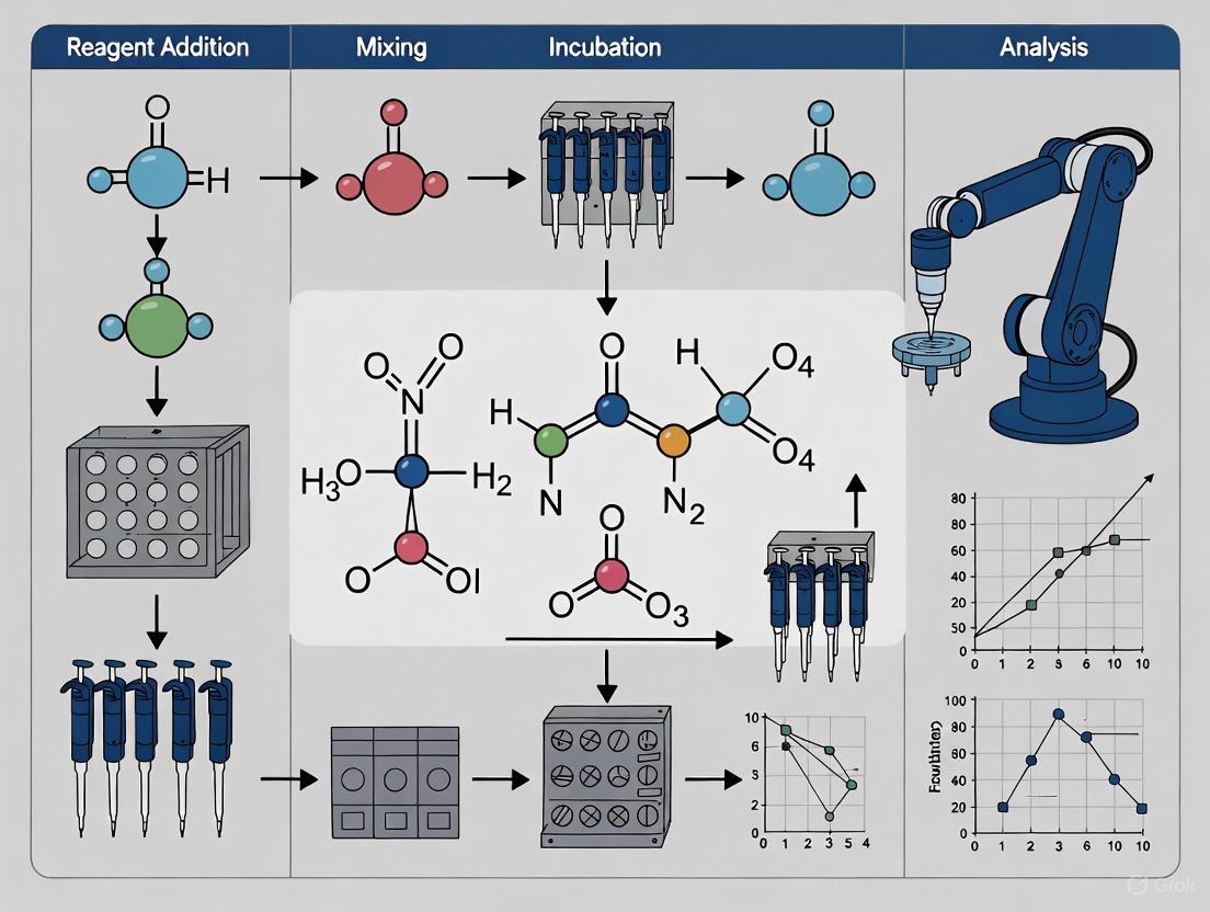
Diagram 1: Comprehensive HTE workflow integrating advanced liquid dispensing, showing the three primary phases of experimental design, automated setup, and analysis with key quality considerations.
Precision liquid dispensing serves as the fundamental enabler of robust, reproducible, and cost-effective HTE workflows. The implementation of appropriate liquid handling technologies—whether acoustic, tipless, or positive displacement systems—directly determines the success of high-throughput reaction arrays in drug discovery and development. As HTE methodologies continue to evolve toward increasingly miniaturized formats and more complex experimental designs, the critical role of advanced dispensing technologies will only intensify. By adhering to the protocols, utilizing the essential research tools, and understanding the quantitative impacts outlined in this application note, researchers can fully leverage liquid dispensing capabilities to accelerate scientific discovery while maintaining the highest standards of data quality and reproducibility.
In high-throughput reaction arrays research, the accurate and precise transfer of liquids is a foundational step that directly impacts the reliability and reproducibility of experimental outcomes. The move towards miniaturization and increased throughput in fields like drug discovery and genomics has placed unprecedented demands on liquid handling technologies. This Application Note provides a detailed comparison of the three principal liquid handling technologies—Air Displacement, Positive Displacement, and Acoustic Droplet Ejection. Aimed at researchers, scientists, and drug development professionals, this document outlines the operational principles, optimal application ranges, and specific experimental protocols for each technology. Furthermore, it provides a structured framework for selecting the appropriate technology based on specific experimental parameters, thereby ensuring data integrity and operational efficiency in high-throughput environments.
Automated liquid handling systems have become indispensable in modern laboratories, transforming workflows by increasing throughput, standardizing accuracy, and freeing highly-trained personnel from repetitive tasks [8] [9]. The core of these systems lies in their dispensing technology, each designed to overcome specific challenges associated with manual pipetting and different liquid types.
The following workflow diagram illustrates the primary decision-making process for selecting an appropriate liquid handling technology based on sample volume and liquid properties:
Figure 1: A workflow for selecting liquid handling technology based on application requirements.
The table below provides a quantitative comparison of the three core technologies to guide initial selection:
Table 1: Comparative Analysis of Key Liquid Handling Technologies
| Parameter | Air Displacement | Positive Displacement | Acoustic Technology |
|---|---|---|---|
| Typical Volume Range | 0.5 µL - 1000 µL [10] [11] | 25 nL - 10 µL (Automated) [10] | 2.5 nL - 5 µL [10] |
| Optimal Liquid Types | Aqueous samples; challenging for viscous, volatile, or particulate-laden liquids [10] [12] | All types, especially viscous, volatile, dense, or surfactant-containing liquids [10] [13] [14] | A wide range of aqueous and complex reagents; compatible with DMSO [10] [2] |
| Key Advantages | Simple, robust mechanism; disposable tips minimize cross-contamination [10] [11] | Liquid-class agnostic; high accuracy for low volumes and challenging liquids; minimal cross-contamination with disposable tips [10] [13] [14] | True non-contact transfer; no tip costs or waste; exceptionally high throughput; enables assay miniaturization [10] [2] [9] |
| Primary Limitations | Performance varies with liquid properties; less accurate at low volumes; requires parameter optimization for non-standard liquids [10] [12] | Higher consumable cost per tip; fewer automated platforms available [10] | Slower for larger volumes; requires inverted destination plate; unable to perform in-well mixing; high initial instrument cost [10] |
| Suitability for High-Throughput Reaction Arrays | Excellent for standard, aqueous-based assays in 96- to 1536-well formats [8] | Ideal for complex reaction arrays involving diverse liquid types and low volumes [13] [15] | Unparalleled for ultra-high-throughput screening and assay miniaturization in 1536-well formats and beyond [2] [9] |
Detailed Technology Profiles
Air Displacement Pipetting
Air displacement, the most widely used technology, relies on an air cushion between a piston and the liquid. The movement of the piston creates positive or negative pressure to aspirate and dispense liquid [10]. While highly accurate for standard aqueous applications above 2 µL, its performance can be significantly compromised by liquid properties. The compressible air cushion makes it susceptible to inaccuracies when handling viscous, volatile, or high-density liquids [10] [12]. For high-throughput workflows involving standard reagents, it remains a cost-effective and robust solution, particularly with disposable tips to prevent cross-contamination.
Protocol: Optimization for Viscous Liquids
The following protocol, adapted from Velasco et al. (2024), provides a systematic method for optimizing air displacement pipetting parameters for viscous liquids using a Multi-Objective Bayesian Optimization (MOBO) algorithm [12].
Application: Accurate transfer of viscous liquids (e.g., glycerol solutions, polymer stocks) with viscosities >100 cP using air displacement pipettes. Objective: To identify optimal aspiration and dispense rates that minimize percentage transfer error and total transfer time.
Materials and Equipment:
- Automated Pipetting System: e.g., Opentrons OT-2 with a single-channel pipette, or Sartorius rLine electronic pipette on a robotic arm [12].
- Balance: Automated microbalance with data logging capability.
- Liquids: Newtonian viscosity standards or target viscous liquids (e.g., 204 - 1275 cP) [12].
- Labware: Appropriate source and destination vessels (e.g., glass vials).
Method:
- Initialization: Define the parameter search space for aspiration and dispense flow rates (e.g., 1-1000 µL/s). Perform a small set of initial gravimetric tests to narrow the feasible range.
- MOBO Setup: Configure the MOBO algorithm with two objectives:
- Minimize the absolute value of the percentage transfer error.
- Minimize the total transfer time for a defined volume (e.g., 1000 µL).
- Iterative Testing Loop: a. The MOBO algorithm suggests a new set of parameters (aspiration rate, dispense rate). b. Aspiration: The pipette aspirates the target volume using the suggested aspiration rate. The tip is submerged to a predetermined depth. c. Equilibration: The pipette pauses (e.g., 5-10 seconds) to allow the air cushion pressure to equilibrate [12]. d. Dispensing: The target volume is dispensed into a pre-weighed destination vial using the suggested dispense rate. e. Gravimetric Analysis: The mass of the transferred liquid is recorded automatically. f. Data Feedback: The percentage transfer error and transfer time are calculated and fed back to the MOBO algorithm.
- Termination: The loop continues for a set number of iterations or until the percentage transfer error is consistently within the acceptable limit (e.g., <5%).
Validation: Compare the MOBO-optimized parameters against those derived from manual intuition. The optimized parameters should achieve equivalent or better accuracy with reduced transfer times, enhancing throughput [12].
Positive Displacement Pipetting
Positive displacement technology eliminates the air gap by employing a piston that makes direct contact with the liquid. This piston, often integrated into a disposable tip, moves within a capillary to aspirate and dispense liquid directly [13] [14]. This direct fluid-mechanical coupling makes it impervious to the effects of liquid viscosity, density, vapor pressure, or surface tension. Consequently, it delivers exceptionally accurate and repeatable pipetting across a broad volume and viscosity range without requiring laborious liquid-class optimization [10] [13]. This "liquid-class agnostic" characteristic is particularly valuable in high-throughput reaction arrays where reagents may have diverse physical properties.
Protocol: Low-Volume Serial Dilution for Dose-Response Assays
This protocol outlines the use of a positive displacement liquid handler, such as the mosquito or F.A.S.T. system, to perform highly accurate serial dilutions in 384- or 1536-well plates for dose-response studies [13] [15].
Application: Preparation of compound dilution series for high-throughput screening (HTS) and IC50/EC50 determination. Objective: To generate a precise logarithmic dilution series of compounds in nanoliter volumes.
Materials and Equipment:
- Liquid Handler: Positive displacement system (e.g., SPT Labtech's mosquito, Formulatrix F.A.S.T.) [13] [15].
- Tips: Manufacturer-specific disposable positive displacement tips.
- Microplates: 384-well source plate containing compounds, and a 384-well or 1536-well destination assay plate.
- Diluent: Appropriate buffer or medium.
Method:
- Plate Layout Definition: In the instrument software, define the layout of the source compound plate and the destination assay plate.
- Protocol Programming: a. Transfer Compound: Using the positive displacement tips, transfer a precise nanoliter-volume aliquot of the compound from the source well to the first well of the dilution series in the destination plate. b. Diluent Addition: Dispense a larger volume of diluent into the same well. c. Mixing: The instrument performs an in-well mixing cycle by repeatedly aspirating and dispensing the liquid within the well using the same tip. d. Serial Transfer: Aspirate a defined volume from the first well and transfer it to the second well containing fresh diluent. e. Repeat: Repeat steps 2b-d down the column to create the serial dilution.
- Execution: Run the protocol. The system will use its integrated piston tips to perform all liquid handling steps with high precision.
- Quality Control: Verify dilution accuracy by including a control compound and measuring the resulting assay signal against expected values.
Key Advantages: The technology ensures that the volume dispensed is independent of the liquid's properties, guaranteeing consistent dilution ratios across different compounds, even those that are viscous or dissolved in DMSO [13]. The disposable tips entirely prevent carryover and cross-contamination between different compounds.
Acoustic Droplet Ejection
Acoustic liquid handling is a truly non-contact technology that uses sound energy, specifically acoustic droplet ejection (ADE), to transfer liquids. A transducer focuses acoustic energy on the surface of the liquid in a source well, ejecting a precisely sized droplet upward onto an inverted destination plate [10] [2] [9]. This method allows for the transfer of volumes in the picoliter to nanoliter range with high accuracy and precision. A key feature of modern acoustic handlers is Dynamic Fluid Analysis (DFA), which automatically determines optimal transfer parameters at runtime for a specified fluid, eliminating the need for manual calibration per liquid type [2]. This technology is transformative for ultra-high-throughput applications, as it eliminates the consumable cost and waste associated with pipette tips and enables massive miniaturization.
Protocol: Creation of Assay-Ready Plates for HTS
This protocol describes the use of an acoustic liquid handler (e.g., Labcyte Echo) to create assay-ready plates by directly transferring compounds from a storage plate into a plate containing assay buffer or cells [2].
Application: Rapid, contact-free reformatting of compound libraries into assay plates for high-throughput screening. Objective: To create hundreds to thousands of assay-ready plates with nanoliter precision, minimizing reagent usage and maximizing throughput.
Materials and Equipment:
- Acoustic Liquid Handler: e.g., Labcyte Echo 655T [2] [9].
- Source Plates: Acoustically compatible microplates (e.g., 384-well) containing compounds in DMSO.
- Destination Plates: 384-well or 1536-well plates, prefilled with assay buffer or cells.
Method:
- System Setup: Place the source compound plate and the destination assay plate on the instrument deck. The destination plate is positioned inverted over the source plate.
- Plate Mapping: The software maps the location of each compound in the source plate to the desired well in the destination plate.
- Transfer Definition: Specify the transfer volume for each compound. The system can perform 1-to-1, many-to-1, or 1-to-many transfers with high flexibility.
- Automated Transfer: a. The instrument uses DFA to characterize the fluid properties in each source well automatically. b. Based on the DFA results, it calculates the precise acoustic energy required to eject a droplet of the specified volume. c. Sound energy is applied, ejecting nanoliter-scale droplets from the source well to the corresponding inverted destination well. d. This process repeats at high speed (up to hundreds of droplets per second) until all transfers are complete [2].
- Plate Sealing and Output: Once the transfer cycle is finished, the destination plate is sealed and is ready for the subsequent assay step.
Key Advantages: The non-contact nature eliminates cross-contamination and compound loss due to adsorption on tip surfaces. The massive miniaturization (e.g., into 1536-well format) drastically reduces reagent consumption and compound usage, leading to significant cost savings [2] [9]. A case study from Evotec demonstrated the preparation of 27 million compounds using acoustic technology, highlighting its critical role in modern drug discovery [2].
The Scientist's Toolkit: Essential Research Reagent Solutions
The table below catalogs key reagents and materials frequently used in conjunction with liquid handling technologies for high-throughput reaction arrays.
Table 2: Key Research Reagent Solutions for High-Throughput Liquid Handling
| Item | Function/Application | Technology Association |
|---|---|---|
| Viscosity Standards (Newtonian Fluids) | Calibration and optimization of liquid handling parameters for viscous liquids [12]. | Air Displacement, Positive Displacement |
| DMSO-soluble Compound Libraries | Stock solutions for small molecule screening; transferred via acoustic ejection or positive displacement [2] [9]. | Acoustic, Positive Displacement |
| Low-Binding/Non-Stick Microplates | Minimizes analyte adhesion to plastic surfaces, critical for low-volume transfers. | All Technologies |
| Acoustically Compatible Source Plates | Specially designed plates with clear bases and optimal well geometry for efficient acoustic droplet ejection [2]. | Acoustic |
| Disposable Positive Displacement Tips | Integrated piston tips that guarantee accuracy and prevent cross-contamination for challenging liquids [13] [15]. | Positive Displacement |
| Filter Tips | Prevents aerosol contamination and liquid from entering the pipette barrel, protecting the instrument [11]. | Air Displacement |
| Master Mixes for PCR/NGS | Pre-mixed reagents for genomics applications, often dispensed in bulk using non-contact dispensers [15]. | All Technologies (esp. Bulk Dispensers) |
| 15-Hydroxy Lubiprostone | 15-Hydroxy Lubiprostone, MF:C20H34F2O5, MW:392.5 g/mol | Chemical Reagent |
| Bimatoprost isopropyl ester | Bimatoprost isopropyl ester, MF:C26H38O5, MW:430.6 g/mol | Chemical Reagent |
The selection of an appropriate liquid handling technology is a critical strategic decision that governs the efficiency, cost, and success of high-throughput reaction array research. Air displacement pipetting offers a robust and economical solution for standard aqueous applications. In contrast, positive displacement technology provides a versatile and precise tool for laboratories handling diverse, challenging liquid types without the need for extensive parameter optimization. Acoustic droplet ejection stands as a powerful technology for ultra-high-throughput settings, enabling unprecedented miniaturization and eliminating consumable waste. By aligning the strengths of each technology with specific experimental requirements—as guided by the protocols and comparisons within this Application Note—research teams can significantly enhance their operational workflow, data quality, and overall scientific output.
The global market for liquid handling systems and related automation is experiencing robust growth, driven by the increasing demand for efficiency and precision in life sciences research. This expansion is quantified by several key metrics across adjacent markets, as detailed in Table 1.
Table 1: Market Growth Projections for Liquid Handling and Adjacent Sectors
| Market Segment | Market Size (2025) | Projected Market Size (2030-2034) | Projected CAGR | Source/Region |
|---|---|---|---|---|
| Liquid Handling System Market | USD 5.1 billion | USD 7.4 billion (2030) | 8.0% (2025-2030) | Global [16] |
| High Throughput Screening (HTS) Market | USD 26.12 billion | USD 53.21 billion (2032) | 10.7% (2025-2032) | Global [17] |
| Lab Automation Market | USD 8.36 billion | USD 14.78 billion (2034) | 6.55% (2025-2034) | Global [18] |
| North America Automated Liquid Handlers Market | USD 1.68 billion | USD 4.05 billion (2033) | 11.8% (2026-2033) | North America [19] |
This growth is primarily fueled by the escalating demand for automated solutions in drug discovery processes, where they streamline complex tasks, enhance precision, and significantly increase throughput for activities like high-throughput screening (HTS) [16]. The integration of Artificial Intelligence (AI) and robotics is a key disruptive trend, improving efficiency, lowering costs, and enabling predictive analytics and advanced pattern recognition in data analysis [17] [18]. Furthermore, the rising focus on personalized medicine and the need to manage large sample volumes and complex testing flows with reduced human intervention are also major contributors to adoption [19] [18].
Regionally, North America holds the dominant market share, supported by a strong biotechnology and pharmaceutical ecosystem, advanced research infrastructure, and substantial R&D spending [17] [18]. However, the Asia-Pacific region is anticipated to be the fastest-growing market, fueled by rapid expansion of its pharmaceutical and biotechnology industries, increasing government funding for life sciences, and rising investments in healthcare infrastructure [16] [17].
Key Drivers and Industry Adoption Trends
The transition from manual processing to automated liquid handling represents a fundamental shift in the scale and reliability of chemical and biological analyses [20]. Several interconnected factors are driving this adoption across the industry.
Operational Imperatives and Technological Advancements
- Demand for Speed and Reproducibility: Modern drug discovery requires massive parallel experimentation to explore compound libraries and validate targets. Automated liquid handling systems enable this by allowing hundreds of thousands of compounds to be tested simultaneously against biological targets, dramatically accelerating hit-to-lead timelines [20] [21]. A core scientific principle guiding HTS is the generation of robust, reproducible data sets under standardized conditions, which is quantified using metrics like the Z-factor to assess assay robustness [20].
- Miniaturization and Precision: HTS relies on miniaturization, primarily using 96-, 384-, or 1536-well microplates to conserve expensive reagents and reduce reaction volumes. This demands extreme precision in fluid handling—often down to nanoliter volumes—which manual pipetting cannot reliably deliver across thousands of replicates [20] [21]. Automated systems provide the sub-microliter accuracy and low dead volume required for these workflows [20].
- Data Integrity and Management: Every microplate processed in an HTS workflow generates thousands of raw data points. Managing this immense data output requires robust informatics systems, such as Laboratory Information Management Systems (LIMS), to ensure data integrity, track compounds, apply correction algorithms, and facilitate accurate hit identification [20].
Evolving Strategic Priorities
For companies and research institutions, strategic priorities are evolving to focus on:
- Enhancing System Intelligence and Flexibility: Integrating advanced analytics and machine learning to optimize workflows, predict maintenance needs, and adapt to diverse experimental protocols with minimal human intervention [19].
- Workflow Integration and Modularity: The core of an HTS platform is the integration of diverse instrumentation—liquid handlers, plate readers, incubators, and washers—through sophisticated robotics and scheduling software for continuous, 24/7 operation [20]. There is a growing emphasis on modular automation systems that can be easily configured for diverse experimental needs [18].
- Sustainability and Cost-Effectiveness: Automated systems reduce reagent waste by enabling reaction miniaturization, cutting reagent volumes by up to a factor of 10 in some cases [21]. The use of non-contact dispensing also minimizes the consumption of single-use plastic consumables like pipette tips, thereby reducing plastic waste and associated costs [21].
Application Note: Automated Next-Generation Sequencing (NGS) Library Preparation
Experimental Protocol
Next-Generation Sequencing (NGS) library preparation is a complex, multi-step process that is prone to human error and variability when performed manually. Automating this workflow with a liquid handler significantly enhances throughput, reproducibility, and data quality [21]. The following protocol is designed for a high-throughput research setting.
Table 2: Research Reagent Solutions for Automated NGS Library Prep
| Item | Function | Considerations for Automation |
|---|---|---|
| Fragmentation & End-Repair Enzymatic Reagents | Cleaves DNA into desired fragment size and repairs ends for adapter ligation. | Precision in dispensing is critical; inaccuracies directly impact library generation efficiency [21]. |
| Adapter Ligation Mix | Attaches platform-specific adapters to DNA fragments. | Automated cleanup post-ligation is essential to remove excess adapters and prevent interference in downstream steps [21]. |
| PCR Master Mix | Amplifies adapter-ligated DNA fragments to enrich for successfully ligated fragments. | Any pipetting errors or contamination at this stage are amplified by PCR, leading to biased results [21]. |
| Magnetic Beads | Used for purification and size selection to remove unwanted fragments and reagents. | Integrated automated cleanup devices increase yields and ensure purity. Manual washing steps are a major source of variability [21]. |
| NGS Library Quantification Kit | Accurately measures library concentration for normalization. | Automated liquid handlers can perform precise volume adjustments to standardize library concentrations across all samples [21]. |
Procedure:
- Sample and Reagent Plate Setup: Place the source plate containing genomic DNA samples and a reagent cooler plate with all necessary enzymes, buffers, and master mixes onto the deck of the automated liquid handler.
- Fragmentation and End-Repair:
- The liquid handler transfers a precise volume of each DNA sample from the source plate to a new microplate.
- It then adds the enzymatic reagents for fragmentation and end-repair to each well. The system's software controls incubation times and temperatures for these reactions.
- Adapter Ligation:
- Upon completion of end-repair, the liquid handler dispenses the adapter ligation mix into the plate.
- After incubation, an integrated automated cleanup system (e.g., a magnetic bead-based purifier) is used to remove enzymes, salts, and excess adapters. The purified product is eluted into a new plate.
- PCR Amplification:
- The liquid handler transfers the purified, adapter-ligated DNA to a PCR plate.
- It precisely aliquots the PCR master mix into each well. The plate is then sealed and transferred by the robotic arm to an integrated thermocycler for amplification.
- Final Cleanup and Normalization:
- Post-amplification, the plate undergoes a final magnetic bead-based cleanup to remove PCR artifacts and primers.
- The liquid handler then quantifies the libraries (e.g., via fluorescence) and automatically normalizes them to an equimolar concentration in preparation for sequencing.
Workflow Diagram: Manual vs. Automated NGS Prep
Application Note: Automated Cell-Based Assays for Drug Discovery
Experimental Protocol
Cell-based assays are critical in drug discovery as they more accurately replicate complex biological systems compared to biochemical methods, offering higher predictive value for clinical outcomes [17]. Automating these assays ensures consistency, reduces contamination, and enables high-throughput screening of compound libraries.
Table 3: Research Reagent Solutions for Automated Cell-Based Assays
| Item | Function | Considerations for Automation |
|---|---|---|
| Cell Line | The biological model for the assay (e.g., engineered reporter cells). | Requires consistent culture and seeding density. Automated cell counters and dispensers ensure uniformity [17]. |
| Cell Culture Media | Supports cell growth and viability. | Liquid handler must maintain sterility during dispensing to prevent contamination [21]. |
| Compound Library | Collection of small molecules or biologics being screened for activity. | Stored in microplates. The liquid handler serially dilutes compounds and transfers them to the assay plate [20]. |
| Assay Reagents | Detect cellular responses (e.g., viability, apoptosis, signaling). | Addition is time-sensitive. Automation allows for precise timing and mixing across the entire plate [17]. |
| Fixation/Staining Buffers | Preserve cells and label cellular components for imaging. | Often toxic. Automation minimizes researcher exposure and ensures consistent application [20]. |
Procedure:
- Cell Seeding:
- An automated liquid handler dispenses a uniform suspension of cells in culture media into the wells of a microplate (e.g., 384-well). The system is housed inside a sterile laminar flow hood or an enclosed environment to maintain aseptic conditions.
- Incubation:
- The cell plate is transferred by a robotic arm to an integrated COâ‚‚ incubator, where it remains for a predetermined period to allow cell attachment and growth.
- Compound Addition:
- The liquid handler performs serial dilutions of the test compounds from a source plate.
- It then transfers a precise volume of each dilution to the cell plate. Controls (positive/negative/vehicle) are included and dispensed by the same system.
- Incubation for Response:
- The plate is returned to the incubator for a set duration to allow the compounds to exert their effects.
- Assay Reagent Addition and Detection:
- The liquid handler adds detection reagents (e.g., for luminescence, fluorescence, or absorbance) to each well.
- The plate is then transported to an integrated multi-mode microplate reader for signal detection. For more complex endpoints, the plate may be moved to an automated imager for high-content analysis.
- Data Acquisition and Analysis:
- The reader or imager captures raw data, which is automatically streamed to a data management system (LIMS). Software calculates key metrics like Z-factor, signal-to-background ratio, and compound efficacy.
Workflow Diagram: Integrated HTS Screening Platform
Reaction miniaturization is the process of scaling down assays to decrease the total assay volume while maintaining accurate and reliable results [22]. This transformation is enabling next-generation high-throughput workflows in diverse areas of life sciences, including drug discovery, genomics, proteomics, and diagnostics [22]. The shift from traditional milliliter-scale reactions to nanoliter and microliter scales represents a fundamental advancement in experimental science, driven by the need for greater efficiency, reduced costs, and improved sustainability [22]. This application note explores the practical implementation of miniaturized reaction systems within the context of high-throughput reaction arrays and liquid handling automation, providing detailed protocols and performance data to guide researchers in adopting these transformative methodologies.
Performance Metrics of Miniaturized Systems
The quantitative benefits of reaction miniaturization are substantial and measurable. The transition from conventional volumes to miniaturized formats can reduce reagent consumption by up to a factor of 10 while maintaining data quality equivalent to or better than traditional workflows [22]. Specific case studies demonstrate remarkable efficiency gains, including a miniaturized fluid array device for high-throughput cell-free protein synthesis that achieved more than two orders of magnitude reduction in reagent consumption compared with commercially available instruments [23].
Table 1: Comparative Performance Metrics Across Reaction Scales
| Parameter | Traditional Workflows | Miniaturized Systems | Improvement Factor |
|---|---|---|---|
| Typical Reaction Volume | 50-200 µL | 4 nL-20 µL | Up to 10,000x reduction [22] |
| Reagent Consumption | High | 1/10th of recommended volume | 10x reduction [22] |
| Dead Volume | Significant | As low as 1 µL [22] | Substantial reduction |
| Protein Expression Yield | Reference standard | Up to 87x higher for specific proteins [23] | Significant increase |
| Experimental Throughput | Limited by manual operations | High-throughput parallel processing | Dramatic increase [22] |
| Plastic Waste Generation | Significant | Minimized through reduced tip usage [22] | Major reduction |
The performance advantages extend beyond mere volume reduction. In one documented case, protein expression yield in a miniaturized device reached 87 times higher for β-glucoronidase compared to conventional microplates [23]. The concentration of β-galactosidase expressed in such miniaturized systems was quantified at 5.5 μg/μL, demonstrating that miniaturization can enhance rather than compromise experimental outcomes [23].
Essential Research Reagent Solutions
Successful implementation of miniaturized workflows requires specific materials and reagents optimized for small-volume applications. The following table details key components essential for establishing robust miniaturized reaction systems.
Table 2: Essential Research Reagent Solutions for Miniaturized Workflows
| Item | Function | Application Notes |
|---|---|---|
| Advanced Liquid Handlers (e.g., I.DOT Liquid Handler) | Precisely dispenses volumes as small as 4 nL [22] | Enables assay miniaturization; features 1 μL dead volume to reduce reagent waste |
| Miniaturized Fluid Array Devices | Provides platform for high-throughput cell-free protein synthesis [23] | 96-unit configuration allows simultaneous expression of 96 proteins; compatible with screening applications |
| Customizable Variable Files (LAP Format) | Standardizes protocol variables for automation [24] | Enables protocol customization without scripting expertise; supports multiple formats (xlsx, csv, json, txt) |
| Specialized Surface Chemistry Plates | Creates optimal binding conditions for miniaturized assays [22] | Enhances assay sensitivity despite reduced sample volume; critical for antibody-based reactions |
| Cell-Free Protein Synthesis Systems | Enables protein production without living cells [23] | Ideal for high-throughput expression; bypasses cell culture requirements; compatible with drug screening |
| Laboratory Automation Protocol (LAP) Repository | Community resource for standardized, validated automation scripts [24] | Ensures reproducibility; accelerates implementation through modular, experimentally-verified protocols |
Experimental Protocol: Miniaturized Fluid Array for High-Throughput Protein Expression
Background and Principle
This protocol adapts the miniaturized fluid array methodology for cell-free protein synthesis, enabling simultaneous expression of up to 96 different proteins with substantial reductions in reagent consumption [23]. The approach is particularly valuable for functional genomics and drug target validation where rapid production of numerous proteins is required. The system achieves more than two orders of magnitude reduction in reagent consumption compared to commercial instruments while maintaining or improving protein yield [23].
Materials and Equipment
- Miniaturized fluid array device (96-unit configuration)
- Liquid handling robot capable of nanoliter dispensing (e.g., I.DOT Liquid Handler)
- DNA templates for target proteins
- Cell-free transcription/translation system
- Reaction substrates and energy sources
- Detection reagents specific to assay (e.g., fluorescent or colorimetric substrates)
- Microplate reader or appropriate detection instrumentation
Procedure
Device Preparation:
- Configure the miniaturized fluid array device according to manufacturer specifications.
- Ensure all 96 reaction units are clean and free of obstructions.
Template DNA Preparation:
- Dilute DNA templates to appropriate concentrations in nuclease-free water.
- Prepare master mixes for cell-free protein synthesis according to commercial system specifications.
Reaction Assembly:
- Program liquid handler to dispense DNA templates into respective reaction units.
- Add cell-free transcription/translation master mix to each unit.
- Final reaction volumes should be optimized for the specific device (typically sub-microliter scale).
Protein Expression:
- Incubate the fluid array at appropriate temperature (typically 30-37°C) for 1-4 hours.
- Maintain humidity to prevent evaporation in small-volume reactions.
Protein Detection and Analysis:
- Add appropriate detection reagents directly to reaction units.
- Quantify expression using suitable methods (e.g., fluorescence, absorbance).
- For enzyme targets, include specific substrates to assess functional activity.
Drug Screening Application:
- Include test compounds during reaction assembly for inhibitory studies.
- Measure compound effects on synthesized enzymes without harvesting proteins.
- Compare activity in presence vs. absence of test compounds.
Expected Results and Interpretation
Using this protocol, researchers can expect protein expression yields comparable to or exceeding conventional systems. For β-galactosidase, concentrations of approximately 5.5 μg/μL are achievable [23]. The system enables rapid screening of inhibitory compounds, reducing analysis time from days to hours by eliminating protein harvesting steps [23].
Standardization Through Laboratory Automation Protocols (LAP)
The implementation of miniaturized workflows is greatly facilitated by standardization efforts such as the Laboratory Automation Protocol (LAP) Format and Repository [24]. This standardized scripting framework accelerates the creation of new protocols and streamlines implementation of high-throughput workflows involving multiple sequential protocols [24].
Figure 1: LAP modular structure and workflow
The LAP format employs a modular structure with three distinct sections [24]:
- Classes Section: Contains user-defined variables for protocol customization
- Functions Section: Houses standardized functions reusable across different protocols
- Body Section: Includes protocol-specific code for execution
This structure enables researchers to combine multiple LAPs sequentially to execute complex workflows while maintaining standardization and reproducibility [24]. The repository is accessible at www.laprepo.com and includes protocols for various applications including modular cloning assembly, sample consolidation, PCR preparation, and specialized utilities [24].
Implementation Workflow for Miniaturized Reaction Systems
Successful deployment of miniaturized reaction systems requires careful planning and execution. The following workflow outlines the key stages from planning through data analysis.
Figure 2: Miniaturized system implementation workflow
Reaction miniaturization from nanoliter to microliter scales represents a transformative advancement in high-throughput research methodologies. The substantial reductions in reagent consumption, combined with maintained or improved data quality, offer researchers significant advantages in cost efficiency, experimental throughput, and sustainability [22]. The integration of standardized automation protocols through initiatives like the LAP Format further enhances reproducibility and accessibility of these advanced methodologies [24]. As the field continues to evolve, the adoption of miniaturized reaction systems will play an increasingly critical role in accelerating scientific discovery across drug development, functional genomics, and diagnostic applications.
The integration of advanced liquid handling robots has become a cornerstone of modern high-throughput experimentation (HTE) in chemical research and drug development. These systems have revolutionized the way researchers approach reaction screening and optimization by enabling the rapid and reproducible setup of vast reaction arrays. A critical frontier in this evolution is enhancing the hardware's capability to safely and reliably handle a diverse range of organic solvents and reactive chemical reagents. The compatibility of system components—from fluid paths to seals—with aggressive chemicals directly impacts experimental integrity, operational safety, and the scope of chemistries that can be automated. This application note details key hardware advancements and provides a validated protocol for performing a high-throughput screening of a palladium-catalyzed C–N coupling reaction, a transformation ubiquitous in pharmaceutical synthesis.
Hardware and Reagent Solutions
The expansion of capabilities for organic solvents hinges on the strategic selection of hardware components and an understanding of their chemical compatibility. The following table summarizes critical hardware considerations and reagent solutions for handling demanding chemicals.
Table 1: Research Reagent Solutions and Hardware Compatibility Guide
| Item / Feature | Function / Description | Key Considerations for Solvents/Reagents |
|---|---|---|
| Fluid Path Technology | Transfers liquid from source to destination. | Positive Displacement Tips: Liquid-agnostic, high compatibility with organic solvents [3].Non-contact Diaphragm Pumps: Isolated fluid path (e.g., Mantis, Tempest) minimizes contamination and corrosion risk [3]. |
| Tip Compatibility | Interface with samples and reagents. | Disposable Tips: Essential for avoiding cross-contamination between different reagents or reactions. |
| Liquid Class Agnosticism | System's ability to handle liquids without pre-defined viscosity/surface tension parameters. | Critical for Organic Solvents: Allows dispensing of diverse solvents (e.g., DMSO, toluene, acetonitrile) with high precision without recalibration [3]. |
| Seal & O-Ring Materials | Prevent leaks and internal corrosion. | Use of chemically resistant polymers (e.g., PTFE, FFKM) is vital for longevity when exposed to aggressive solvents. |
| Hold-Up Volume | The volume of liquid retained and potentially wasted in the fluid path. | Low hold-up volume (e.g., ~6 µL in Mantis) is crucial for precious reagents and expensive solvents, minimizing waste and cost [3]. |
| Precision (CV) | Measure of dispensing reproducibility. | Systems must maintain low Coefficient of Variation (e.g., <5% at 100 nL) across different solvent classes to ensure reliable reaction outcomes [3]. |
Application Note: High-Throughput Screening of C–N Cross-Coupling Reactions
Experimental Objective
To systematically evaluate the effect of four distinct phosphine ligand classes on the yield of a challenging palladium-catalyzed C–N bond formation using an automated liquid handling platform, demonstrating a calibration-free quantification workflow.
The Scientist's Toolkit
Table 2: Key Reagents and Materials
| Item | Function / Role in Experiment |
|---|---|
| Liquid Handler | Automated pipetting system (e.g., with 8-channel individually addressable tips) for precise reagent dispensing. |
| 96-Well Reaction Plate | SBS-standard microplate for conducting parallel reactions. |
| Aryl Halide Substrate | Electrophilic coupling partner. |
| Amine Substrate | Nucleophilic coupling partner. |
| Palladium Catalyst | Transition metal catalyst (e.g., Pd2(dba)3). |
| Phosphine Ligands (L1-L4) | Four distinct ligands to stabilize the catalytic active site (e.g., BippyPhos, BrettPhos, tBuXPhos, RockPhos). |
| Base | Inorganic base (e.g., Cs2CO3) to facilitate deprotonation. |
| Solvent (Toluene) | Organic solvent to dissolve reagents and facilitate the reaction. |
| GC-MS with Polyarc-FID System | For parallel analysis and calibration-free quantification of reaction yields [25] [26]. |
| pyGecko Python Library | Open-source software for automated, rapid analysis of GC raw data [25] [26]. |
| 3,6,19-Trihydroxy-23-oxo-12-ursen-28-oic acid | 3,6,19-Trihydroxy-23-oxo-12-ursen-28-oic acid, MF:C30H46O6, MW:502.7 g/mol |
| NHPI-PEG4-C2-Pfp ester | NHPI-PEG4-C2-Pfp ester, MF:C25H24F5NO9, MW:577.4 g/mol |
Automated Workflow for Reaction Setup
The following diagram illustrates the high-throughput workflow for setting up and analyzing the reaction array.
Step-by-Step Protocol
Step 1: Experimental Design and Worklist Generation
- Using HTE software (e.g., phactor), design a 96-reaction array where each well contains a constant concentration of the aryl halide, amine, palladium catalyst, and base, but varies the ligand identity across four groups (L1-L4) with 24 replicates per ligand [27].
- The software will generate a worklist specifying the volume of each stock solution to be transferred to each well of the destination 96-well plate. This worklist can be optimized using algorithms (e.g., formulated as a Capacitated Vehicle Routing Problem) to reduce liquid handling execution time by up to 37% [28].
Step 2: Reagent and Instrument Preparation
- Prepare stock solutions of all reagents in dry, anhydrous toluene to ensure consistency and prevent catalyst deactivation. Typical concentrations are 0.1 M for substrates.
- Prime the liquid handler, ensuring it is equipped with solvent-resistant fluid paths and disposable tips compatible with organic solvents. Load the stock solutions into designated source labware (e.g., 12-well reservoir).
Step 3: Automated Liquid Transfer
- Execute the optimized worklist generated in Step 1. The liquid handler will sequentially dispense the specified volumes of toluene, amine, base, aryl halide, ligand, and catalyst into each well.
- Critical Note: The order of addition can be crucial. A common practice is to add the catalyst last to initiate the reaction uniformly across the plate after all other components have been mixed.
Step 4: Reaction Execution and Quenching
- Seal the 96-well plate with a chemically resistant, heat-stable seal.
- Place the plate on an orbital shaker with heating and incubate at the desired temperature (e.g., 80°C) for the set reaction time (e.g., 18 hours).
- After incubation, quench the reactions by using the liquid handler to add a fixed volume of a quenching solvent (e.g., acetonitrile) containing an internal standard if required for alternative analytical methods.
Step 5: Analysis and Data Processing
- Use the liquid handler to transfer an aliquot from each well to a GC analysis plate.
- Analyze the samples using a parallel GC-MS and GC-Polyarc-FID system. The Polyarc system enables calibration-free quantification by converting all organic compounds to methane, allowing the FID to respond on a per-carbon-atom basis, thus providing direct mass quantification without pure product standards [25] [26].
- Process the raw GC data using the pyGecko open-source Python library. This tool can automatically determine reaction outcomes (e.g., conversion, yield) for the entire 96-reaction array in under one minute [25] [26].
Data Analysis and Optimization Strategies
The output from pyGecko yields a quantitative yield for each of the 96 reactions. This data can be visualized as a heatmap to quickly identify the most effective ligand.
Liquid Handling Optimization: For complex screening campaigns, optimizing the liquid handling schedule itself is critical. Reformulating the pipetting task as a Capacitated Vehicle Routing Problem (CVRP) can lead to substantial time savings. One study demonstrated that 3 minutes of optimization planning reduced the liquid handling execution time by 61 minutes in a real-world materials discovery campaign [28].
Future Outlook: The maturation of AI-guided tools is set to further revolutionize this field. These tools can predict optimal reaction conditions and design safer, more sustainable synthetic pathways by prioritizing green chemistry principles, such as the replacement of toxic organic solvents with water where possible or the design of solvent-free synthetic routes [29]. This aligns with the growing trend in green chemistry to substitute traditional solvents with bio-based alternatives or water in industrial applications [29] [30].
From Plan to Plate: Implementing HTE Workflows and Software Integration
Streamlining Experiment Design with Software like phactor
The evolution of hardware for running High-Throughput Experimentation (HTE) in chemical laboratories has created a corresponding need for software solutions to navigate data-rich experiments [27]. While laboratories have gravitated toward standardized liquid handling techniques in 24, 96, 384, or 1,536 wellplates, a standardized approach for HTE data handling had been lacking [27]. Managing the organizational load for even a simple 24-well reaction array through traditional notebook entries or spreadsheets becomes challenging when scaling to multiple daily reaction arrays or ultraHTE in 1,536 wellplates [27]. The phactor software was developed to address this critical gap, providing researchers with a streamlined solution for the design, execution, and analysis of HTE that integrates seamlessly with liquid handling robotics [27] [31].
This application note details how phactor facilitates performance and analysis of HTE in chemical laboratories, enabling experimentalists to rapidly design arrays of chemical reactions or direct-to-biology experiments [27]. By storing all chemical data, metadata, and results in machine-readable formats, the software ensures data is readily translatable to various software platforms and positioned for machine learning studies [27]. The integration of phactor with automated liquid handling systems creates a closed-loop workflow for HTE-driven chemical research, significantly accelerating reaction discovery and optimization while maintaining data standardization [27].
The phactor workflow is optimized to minimize the time and resources spent between experiment ideation and result interpretation [27]. The software guides users through six distinct stages: Settings, Factors, Chemicals, Grid, Analysis, and Report [32] [31]. This structured approach enables even novice scientists to create and execute robust yet flexible reaction arrays while ensuring comprehensive data capture [31].
Six-Stage Experimental Workflow
The following diagram illustrates the complete phactor workflow from initial setup to final reporting:
Figure 1: The complete phactor workflow from experimental design through analysis and reporting
Stage-by-Stage Protocol
Settings Stage: Begin by naming your experiment and specifying the throughput (24 or 96 wells for the free academic version) and the desired reaction volume for each well (typically 100 µL at these throughputs) [32]. Click 'Create Screen' to proceed to the next stage.
Factors Stage: Input the experimental design in terms of reagent distributions to enable automated plate design [32]. For example, for a 24-well experiment screening 4 ligands and 6 catalysts, input '4' and '6' into the respective textboxes. Record additional experimental metadata including stir rate, temperature, and solvent. Optionally, define expected products and side products with associated SMILES strings and descriptive names using the provided CSV template [32].
Chemicals Stage: Add substrates and reagents planned for use in the reaction array [32]. Chemicals can be added:
- Manually via the form at the bottom of the page
- From the provided database of common reagents by clicking "Add From Database"
- Via CSV template with specific headers including chemicalName, molarMass, molarity, smiles, and factor type [32] The checklist in the bottom left indicates progress toward satisfying the factors defined in the previous stage [32].
Grid Stage: Review the automatically generated experimental design in an interactive wellplate display [32] [31]. Make manual adjustments to individual wells or use bulk editing functions by dragging over multiple wells [32]. Download stock solution recipes from the table on the left and record true weighted masses of reagents to recalculate solvent volumes [32]. Download the 'Wellplate recipe' for experimental setup.
Analysis Stage: Upload analytical results via CSV file with required headers including Sample Name (well label), productsmiles, productyield, and product_name [32]. Visualize results through interactive heatmaps that display inputs, outputs, output values, and molecular structures when cells are clicked [32].
Report Stage: Generate comprehensive outputs displaying information regarding the performed experiment [32]. Download results in machine-readable format for further analysis or integration with other software platforms [32].
Integration with Liquid Handling Robotics
phactor seamlessly integrates with liquid handling robotics, bridging the gap between experimental design and physical execution [27]. The software generates instructions that can be executed either manually or with the assistance of liquid handling robots [27]. This integration has been demonstrated with various robotic systems, including the Opentrons OT-2 liquid handling robot for experiments of 384-well throughput or less, and the SPT Labtech mosquito robot for 1,536-well ultraHTE [27].
Optimization of Robotic Liquid Handling
Recent research has demonstrated that liquid handling operations can be significantly optimized by formulating the task as a Capacitated Vehicle Routing Problem (CVRP) [28] [33]. This approach, particularly beneficial for 8-channel pipettes with individually controllable tips, can reduce execution time by up to 37% for randomly generated tasks compared to baseline sorting methods [28] [33]. In a real-world high-throughput materials discovery campaign, just 3 minutes of optimization time led to a reduction of 61 minutes in execution time compared to the best-performing sorting-based strategy [28] [33].
The following diagram illustrates the CVRP optimization concept for liquid handling robots:
Figure 2: CVRP optimization framework for liquid handling robotics
Protocol for Robot Integration
After completing the Grid stage in phactor, download the appropriate robot instruction file format for your specific liquid handling system.
Transfer the instruction file to the liquid handling robot's control software following the manufacturer's protocol.
Implement the CVRP optimization strategy for 8-channel pipettes by:
- Defining the liquid handling task as a matrix of (source, destination, volume) transfers [28]
- Applying heuristic solvers traditionally used in logistics and transportation planning [28]
- Accounting for labware-specific geometric constraints (96-well plates allow all eight tips to simultaneously access a single column, while 384-well plates require tip placement at every other well to avoid collisions) [28]
Execute the optimized liquid handling protocol, which will distribute stock solutions to their respective locations on the reaction wellplate.
For last-minute changes due to unforeseen circumstances (poor chemical solubility, chemical instability, or need to premix reagents before dosing), make adjustments in the phactor Grid stage and regenerate instructions [27].
Research Reagent Solutions and Essential Materials
Successful implementation of phactor-drided HTE requires specific materials and reagents organized in a structured workflow. The table below details essential components for establishing an HTE platform integrated with phactor software:
Table 1: Essential research reagent solutions and materials for phactor-driven HTE
| Item Category | Specific Examples | Function in HTE Workflow |
|---|---|---|
| Wellplate Formats | 24, 96, 384, 1,536-well plates [27] | Standardized vessels for conducting miniaturized parallel reactions |
| Liquid Handling Robots | Opentrons OT-2, SPT Labtech mosquito [27] | Automated dispensing of reagents and solutions with precision |
| Chemical Inventory | Online database with SMILES, molecular weight, density [27] [32] | Source of reagent metadata for automated experimental design |
| Analytical Instruments | UPLC-MS systems with automated sampling [27] | High-throughput analysis of reaction outcomes |
| Stock Solutions | Prepared in vials or wellplates at specified molarities [27] [32] | Intermediate solutions for precise reagent dosing |
| Data Analysis Tools | Virscidian Analytical Studio, custom Python scripts [27] | Processing and interpretation of analytical results |
Case Studies and Applications
phactor has been extensively used in research laboratories for various applications, demonstrating its versatility and effectiveness in accelerating scientific discovery.
Reaction Discovery and Optimization
The software has facilitated the discovery of several novel chemistries, particularly in amine-acid coupling reactions [31]. Specific applications include:
Deaminative Aryl Esterification: phactor automatically designed a reagent distribution recipe by splitting a plate into a four-row and six-column multiplexed array to test an amine activated as its diazonium salt, a carboxylic acid, three transition metal catalysts, four ligands, and the presence or absence of a silver nitrate additive [27]. Analysis of UPLC-MS results via phactor identified optimal conditions (18.5% assay yield with 30 mol% CuI, pyridine, and AgNO₃) that were triaged for further study [27].
Oxidative Indolization Reaction: phactor was used to optimize the penultimate step in the synthesis of umifenovir [27]. A reaction array tested four copper sources with combinations of magnesium sulfate and ligands in DMSO solutions [27]. The software identified well B3 (copper bromide with L1 and no magnesium sulfate) as the best performer, with scale-up producing the desired indole in 66% isolated yield [27].
Asymmetric Allylation: Investigation of the allylation of furanone or furan with various reagents where phactor's multiplexed pie charts revealed optimal conditions (2:1 palladium catalyst to ligand loading with no base) that generated the desired γ-regioisomer with the greatest selectivity [27].
Direct-to-Biology Applications
phactor has also proven valuable in direct-to-biology assay development, successfully identifying a novel low micromolar inhibitor of the SARS-CoV-2 main protease through an ultrahigh-throughput direct-to-biology campaign [27] [31]. After an initial 24-well exploratory experiment testing the viability of the chemistry and biology, an inhibitor library was synthesized using amide chemistry on a 1,536-well plate [31]. phactor integrated the chemical and biological results, enabling identification of the best hits that were subsequently scaled up and isolated [31].
Data Management and Standardization
A fundamental advantage of phactor is its robust approach to data management and standardization. The software records experimental procedures and results in a machine-readable yet simple format that naturally translates to other system languages [27]. This data structure enables procedural generation or modification with basic Excel or Python knowledge, facilitating interface with any robot, analytical instrument, or software [27].
The standardization of HTE data output is particularly valuable for building predictive models and machine learning applications [27]. By providing rich, well-annotated datasets in consistent formats, phactor helps address the longstanding challenge of data standardization in high-throughput experimentation, creating opportunities for more sophisticated data analysis and knowledge extraction across multiple experimental campaigns [27].
The transition from One-Factor-at-a-Time (OFAT) to Design of Experiments (DoE) represents a fundamental evolution in scientific research methodology, particularly within high-throughput experimentation. While OFAT has served as a traditional approach for decades, its limitations in capturing complex factor interactions have driven the adoption of more sophisticated statistical frameworks. Liquid handling robots have emerged as critical enablers of this transition, providing the precision, reproducibility, and throughput necessary to implement complex DoE designs efficiently. This paradigm shift is especially crucial in pharmaceutical research and reaction discovery, where optimizing multi-factor processes can accelerate development timelines and improve outcomes.
OFAT methodology involves varying a single factor while holding all others constant, systematically testing factors in isolation [34]. This approach appears intuitively simple but fails to capture interaction effects between factors, potentially leading to suboptimal results and missed opportunities [34] [35]. In contrast, DoE employs structured, simultaneous variation of multiple factors according to statistical principles, enabling researchers to efficiently map complex response surfaces, identify significant interactions, and locate optimal conditions with minimal experimental runs [34] [36].
Comparative Analysis: OFAT versus DoE
Fundamental Characteristics and Limitations
The following table summarizes the core differences between OFAT and DoE approaches:
Table 1: Comparison of OFAT and DoE Methodological Characteristics
| Characteristic | OFAT Approach | DoE Approach |
|---|---|---|
| Factor Variation | Sequential, one factor at a time | Simultaneous, multiple factors together |
| Interaction Detection | Cannot detect factor interactions | Explicitly measures and quantifies interactions |
| Experimental Efficiency | Low; requires many runs for multiple factors | High; maximizes information per experimental run |
| Resource Utilization | Inefficient; consumes more reagents and time [3] | Optimized; achieves more with fewer resources [3] |
| Statistical Foundation | Limited statistical basis | Built on rigorous statistical principles (randomization, replication, blocking) [34] |
| Optimal Condition Identification | Risk of missing true optimum due to interactions [35] | Systematic approach to locating robust optima |
| Implementation Complexity | Simple conceptually, but tedious to execute | Requires upfront planning but streamlined execution |
The primary limitation of OFAT lies in its inability to detect interactions between factors [34] [35]. In complex biological or chemical systems, factors often exhibit interdependent effects that cannot be captured when tested in isolation. For instance, the effect of a catalyst in a reaction may depend significantly on temperature or solvent composition—interactions that OFAT would likely miss. This limitation becomes increasingly problematic as system complexity grows, potentially leading researchers to suboptimal conclusions and missed opportunities for innovation [34].
The Role of Automated Liquid Handling in Enabling DoE
The implementation of DoE methodologies has been dramatically accelerated by advances in automated liquid handling (ALH) systems. These platforms address the primary practical barrier to DoE adoption: the complexity of preparing multiple reagent combinations simultaneously with the required precision and reproducibility [3]. Modern ALH systems provide:
- High Precision and Accuracy: Capable of dispensing volumes as low as 100 nL with coefficients of variation (CV) under 5%, ensuring reproducible experimental conditions essential for meaningful statistical analysis [3].
- Workflow Integration: Seamless connectivity with laboratory information management systems (LIMS) and experimental design software creates closed-loop workflows from experimental design to execution and analysis [37].
- Throughput Capabilities: Enable execution of complex factorial designs that would be impractical manually, including 24-, 96-, 384-, and even 1,536-well formats [37].
- Miniaturization and Cost Reduction: Reduce reagent consumption by up to 60% through miniaturization while generating high-quality screening data [3].
Software platforms like phactor further streamline this process by facilitating the design of reaction arrays and directly generating instructions for liquid handling robots, creating an integrated ecosystem for high-throughput experimentation [37].
Workflow Implementation: Transitioning from OFAT to DoE
The following diagram illustrates the comparative workflows for OFAT versus DoE approaches in high-throughput experimentation:
Comparative Workflows: OFAT vs. DoE - The sequential OFAT approach contrasts with the parallel, statistically-driven DoE methodology enabled by automated liquid handling systems.
Application Notes: DoE Protocol for High-Throughput Reaction Optimization
Protocol: Screening DoE for Reaction Discovery
This protocol outlines the implementation of a screening DoE for high-throughput reaction optimization using automated liquid handling systems, based on demonstrated applications in pharmaceutical research [37] [38].
Objective: Identify significant factors influencing reaction yield in a transition metal-catalyzed coupling reaction.
Materials and Equipment:
- Automated liquid handler (e.g., Opentrons OT-2, Formulatrix Mantis, or Tecan systems)
- 96-well or 384-well reaction plates
- UPLC-MS system for analysis
- phactor software or equivalent DoE design package
- Reagents: Substrates, catalysts, ligands, bases, solvents
Procedure:
Factor Selection and Level Definition (30 minutes)
- Select 4-6 potentially influential factors (e.g., catalyst type, ligand, concentration, temperature, solvent, additive)
- Define high and low levels for each factor based on preliminary knowledge or literature values
- Document factor-level combinations in experimental design matrix
Experimental Design Generation (45 minutes)
- Select appropriate screening design based on factor count:
- 4-8 factors: Plackett-Burman design (12-24 runs)
- 5-10 factors: Fractional factorial design (16-32 runs)
- 6+ factors: Definitive screening design (requires ~2n+1 runs) [36]
- Incorporate center points (3-5 replicates) to estimate experimental error
- Randomize run order to minimize systematic bias
- Select appropriate screening design based on factor count:
Liquid Handler Programming (60 minutes)
- Translate experimental design to robot instructions using phactor or equivalent software [37]
- Define stock solution concentrations and dilution schemes
- Program reagent transfers according to experimental matrix
- Include mixing steps and incubation times as required
Automated Reaction Assembly (2-3 hours)
- Prepare stock solutions of all reagents at appropriate concentrations
- Load reagents and clean tips/consumables onto liquid handler
- Execute automated dispensing protocol
- Seal plates and transfer to controlled temperature environment
Reaction Monitoring and Analysis (Variable)
- Quench reactions at predetermined timepoints
- Analyze yields via UPLC-MS with automated sample injection
- Export conversion data to CSV format for statistical analysis
Statistical Analysis and Model Building (60 minutes)
- Calculate main effects and interaction effects
- Perform ANOVA to identify statistically significant factors (p < 0.05)
- Construct linear model relating factors to response
- Identify promising factor combinations for optimization phase
Research Reagent Solutions for High-Throughput DoE
Table 2: Essential Materials and Reagents for DoE Implementation
| Item | Function | Implementation Example |
|---|---|---|
| phactor Software | Facilitates HTE array design and analysis | Designs 24-, 96-, 384-well plates; generates robot instructions; analyzes results [37] |
| Modular Liquid Handler | Automated reagent dispensing | Opentrons OT-2 for 384-well throughput; SPT Labtech mosquito for 1536-well ultraHTE [37] |
| Multiwell Plates | Miniaturized reaction vessels | 24-, 96-, 384-, or 1,536-well plates for reaction arrays [37] |
| UPLC-MS System | High-throughput reaction analysis | Analyzes reaction outcomes; provides conversion/yield data [37] |
| Chemical Inventory | Reagent database with metadata | Links to molecular weight, CAS numbers, SMILES strings for automated calculation of stoichiometries [37] |
| DESI Mass Spectrometry | Ultra-high-throughput analysis | Screens >10,000 reactions per hour with minimal sample preparation [39] |
Case Study: DoE in Reaction Discovery and Optimization
Deaminative Aryl Esterification Discovery
A practical application of this methodology demonstrated the discovery of a deaminative aryl esterification reaction [37]. Researchers employed a 24-well reaction array to investigate combinations of:
- Diazonium salt (1)
- Carboxylic acid (2)
- Three transition metal catalysts
- Four ligands
- Silver nitrate additive (presence/absence)
The phactor software automatically designed the reagent distribution, splitting the plate into a four-row by six-column multiplexed array. After execution and UPLC-MS analysis, results were uploaded to generate a heatmap visualization, identifying specific conditions (CuI, pyridine, AgNO₃) that provided an 18.5% assay yield [37]. This initial screening would have required 48 individual OFAT experiments to test the same factor combinations but was accomplished in a single plate through DoE methodology.
Market Context and Implementation Trends
The growing adoption of DoE methodologies is reflected in the expanding market for enabling technologies. The global automated liquid handling systems market is projected to grow from $3.26 billion in 2025 to $6.35 billion by 2035, representing a compound annual growth rate of 6.9% [40]. This growth is largely driven by the pharmaceutical and biotechnology sectors, where the limitations of OFAT have become increasingly apparent in complex development environments [41].
Leading players in the automated liquid handling market include Tecan Group, Beckman Coulter, Eppendorf, Hamilton Robotics, and Opentrons, who continue to develop systems with enhanced precision, miniaturization capabilities, and software integration [40] [41]. These technological advances continue to lower the barrier to DoE implementation, making sophisticated experimental designs accessible to a broader range of research laboratories.
The transition from OFAT to DoE represents more than a methodological shift—it constitutes a fundamental transformation in how researchers approach experimental science. By embracing statistically-driven experimental designs enabled by automated liquid handling platforms, researchers can efficiently navigate complex experimental spaces, detect critical factor interactions, and accelerate the discovery and optimization of chemical reactions and biological assays. As liquid handling technologies continue to advance and integrate with artificial intelligence and machine learning platforms, the implementation of sophisticated DoE methodologies will become increasingly accessible, driving innovation across pharmaceutical development, materials science, and chemical research.
High-Throughput Experimentation (HTE) has become a cornerstone of modern drug discovery and chemical research, enabling the rapid screening and optimization of thousands of reactions in parallel. This case study examines a strategic initiative that achieved a 77% increase in HTE execution efficiency within a pharmaceutical research setting. The implementation focused on integrating advanced automation technologies, specifically automated liquid handling and powder dosing systems, to overcome critical bottlenecks in screening workflows.
The drive for this improvement stems from the challenging landscape of drug development. The process of bringing a new drug to market typically takes 12-15 years and costs approximately $2.8 billion from inception to launch [42]. Within this pipeline, initial candidate selection and optimization represent particularly costly and challenging phases. HTE, which encompasses high-throughput screening (HTS) and parallel chemical synthesis, addresses these challenges by massively increasing throughput across all discovery processes while working at significantly smaller scales than traditional methods [42]. This miniaturization not only improves logistics but also substantially reduces environmental impact.
Background and Challenge
The High-Throughput Screening Landscape
The global high-throughput screening market reflects the growing importance of these technologies, with market size estimated at USD 26.12 billion in 2025 and projected to reach USD 53.21 billion by 2032, exhibiting a compound annual growth rate (CAGR) of 10.7% [17]. This significant growth is driven by increasing adoption across pharmaceutical, biotechnology, and chemical industries, all seeking faster drug discovery and development processes.
Within this landscape, liquid handling systems form the technological backbone, with the instruments segment (liquid handling systems, detectors, and readers) expected to lead the market with a 49.3% share in 2025 [17]. The global liquid handling systems market itself was valued at USD 4.34 billion in 2024 and is projected to reach USD 6.75 billion by 2030, growing at a CAGR of 7.64% [43].
Specific Research Challenges
The research team faced several critical challenges that limited HTE efficiency:
- Manual powder dosing bottlenecks: Weighing and dispensing solid reagents, especially at milligram scales, was time-consuming and prone to human error
- Liquid handling inaccuracies: Manual pipetting introduced variability that compromised experimental integrity and reproducibility
- Workflow integration gaps: Disconnected equipment and processes created inefficiencies in sample handling and data management
- Scale correlation concerns: Ensuring that small-scale HTE results would translate reliably to manufacturing scale presented significant validation challenges [44]
These challenges were particularly acute in oncology discovery programs, where the team needed to evaluate increasingly complex reaction arrays with tight timelines for candidate identification.
Experimental Design and Setup
Instrumentation and Automation Systems
The efficiency improvement initiative centered on the implementation of integrated automation systems designed to address specific workflow bottlenecks. The core instrumentation included:
- CHRONECT XPR Workstations: For automated powder dosing with a dispensing range of 1 mg to several grams, handling various powder types including free-flowing, fluffy, granular, or electrostatically charged materials [42]
- Advanced liquid handling systems: Including acoustic dispensing and pressure-driven methods with nanoliter precision to replace error-prone manual pipetting [45]
- Integrated robotic systems: For seamless sample transfer between processing stations and microplate handling
The automated solid weighing systems represented a particular advancement, capable of dosing a wide range of solids including transition metal complexes, organic starting materials, and inorganic additives with high precision [42].
Research Reagent Solutions
Table 1: Essential Research Reagents and Materials
| Reagent/Material | Function in HTE | Application Specifics |
|---|---|---|
| Transition Metal Complexes | Catalysts for cross-coupling reactions | Screening catalyst libraries for reaction optimization |
| Organic Starting Materials | Building blocks for parallel synthesis | Evaluating diverse chemical space in analogue libraries |
| Inorganic Additives | Reaction promoters or modifiers | Optimizing reaction conditions and yields |
| Assay Buffer Systems | Maintaining physiological pH and conditions | Cell-based assays for drug candidate evaluation |
| Cell-Based Assay Reagents | Functional screening of compound libraries | Providing physiologically relevant data [17] |
| CRISPR-Based Screening Tools | Genome-wide studies of biological mechanisms | Identifying novel targets and mechanisms [17] |
Workflow Design and Integration
The experimental workflow was redesigned to create a seamless, integrated process from experimental design to data analysis. Key innovations included:
- Compartmentalized HTE workflows: Separation of solid processing, liquid handling, and reaction validation into dedicated gloveboxes to optimize each environment [42]
- Integrated data management: Direct linkage between experimental parameters, execution data, and analytical results
- Modular experiment design: Implementation of Library Validation Experiments (LVE) to efficiently evaluate building block chemical space against specific reaction variables [42]
The following diagram illustrates the optimized end-to-end workflow implemented to achieve efficiency gains:
Figure 1: Optimized HTE Workflow - The integrated automation pathway from experiment planning to data analysis that enabled significant efficiency improvements.
Protocol: Implementation of Automated HTE
Automated Powder Dosing Protocol
Purpose: To accurately and efficiently dispense solid reagents in milligram quantities for parallel reaction arrays.
Materials:
- CHRONECT XPR automated powder dosing system [42]
- Mettler Toledo standard dosing heads (up to 32 heads)
- Source powder containers
- Target vials (2 mL, 10 mL, 20 mL sealed vials; unsealed 1 mL vials)
- Inert atmosphere glovebox
Procedure:
- System Setup
- Install appropriate dosing heads for specific powder characteristics
- Calibrate system using standard reference materials
- Establish inert atmosphere environment (Nâ‚‚ or Ar) within glovebox
Experiment Programming
- Upload experiment design file with target masses for each reagent
- Define dispensing sequence optimizing for minimal cross-contamination
- Set validation parameters for mass accuracy checks
Powder Dispensing Execution
- System automatically doses solids according to programmed masses
- Typical dispensing time: 10-60 seconds per component
- Real-time mass verification after each dispensing operation
Quality Control
- Verify dispensing accuracy: <10% deviation for masses sub-mg to low single-mg
- Confirm precision: <1% deviation for masses >50 mg [42]
- Document any outliers for manual verification
Automated Liquid Handling Protocol
Purpose: To precisely transfer liquid reagents and solutions while minimizing manual error and variability.
Materials:
- Automated liquid handler with acoustic dispensing capability
- Vendor-approved disposable tips
- Source reagent plates
- 96-well or 384-well microplates
- Assay-specific buffers and solutions
Procedure:
- Liquid Class Optimization
- Define optimal aspirate/dispense parameters for each reagent type
- Configure forward or reverse mode pipetting based on reagent viscosity [46]
- Set appropriate liquid sensing thresholds to avoid air bubble aspiration
Plate Setup and Configuration
- Program deck layout with precise consumable locations
- Define labware types and geometries in system software
- Establish tip waste locations and clean station protocols
Liquid Transfer Execution
- Execute sequential or parallel transfer protocols as required
- Maintain tip depth of 2-3 mm below liquid surface during aspiration [46]
- Implement trailing air gaps to prevent droplet formation and contamination
Process Validation
- Verify volume transfer accuracy using colorimetric or gravimetric methods
- Confirm mixing efficiency through homogeneity testing
- Document system performance for quality assurance records
Integrated Reaction Screening Protocol
Purpose: To execute parallel reaction arrays with integrated solid and liquid handling for comprehensive condition screening.
Materials:
- Prepared solid reagent plates from powder dosing protocol
- Liquid reagent plates from liquid handling protocol
- Temperature-controlled reaction blocks
- Inert atmosphere capability
- Analytical equipment (HPLC, MS, or plate readers)
Procedure:
- Reaction Assembly
- Transfer dosed solids to reaction vessels using automated systems
- Add liquid reagents according to predefined experimental design
- Seal plates and establish appropriate atmosphere conditions
Reaction Execution
- Initiate temperature programs and mixing protocols
- Monitor reaction progress through in-situ analytics where available
- Execute quenching procedures at predetermined timepoints
Sample Analysis
- Transfer aliquots to analysis plates using automated liquid handling
- Conduct parallel analytical measurements (HPLC, MS, UV-Vis)
- Compile raw data into structured database format
Data Processing
- Automate data extraction and normalization procedures
- Apply quality filters to remove outliers and artifacts
- Generate reaction performance metrics for hit identification
Results and Performance Metrics
Quantitative Efficiency Improvements
The implementation of integrated automation systems yielded substantial improvements in HTE execution efficiency across multiple metrics:
Table 2: HTE Performance Metrics Before and After Automation Implementation
| Performance Metric | Pre-Automation Baseline | Post-Implementation Performance | Relative Improvement |
|---|---|---|---|
| Average Screen Size (per quarter) | 20-30 screens | 50-85 screens | ~77% increase [42] |
| Conditions Evaluated (per quarter) | <500 conditions | ~2000 conditions | >300% increase [42] |
| Powder Dosing Time (per vial) | 5-10 minutes (manual) | <30 minutes (96-well plate) | ~85% time reduction [42] |
| Powder Dosing Accuracy (low mass) | Highly variable (manual) | <10% deviation from target | Significant improvement [42] |
| Liquid Handling Reproducibility | Subject to human error | CV <5% for most applications | Major improvement [46] |
Qualitative Workflow Improvements
Beyond the quantitative metrics, the automated system delivered significant qualitative benefits:
- Error Reduction: Elimination of human errors in powder weighing at small scales, which were previously reported as "significant" [42]
- Experimental Reproducibility: Enhanced consistency through elimination of manual handling variability
- Operator Productivity: Liberation of skilled personnel from repetitive tasks to focus on experimental design and data interpretation
- Data Integrity: Improved traceability and documentation through automated data capture
The relationship between specific automation technologies and their impact on overall efficiency is visualized in the following diagram:
Figure 2: Efficiency Drivers - Key automation technologies and their contributions to the overall 77% efficiency improvement.
Discussion
Critical Success Factors
The achievement of a 77% increase in HTE execution efficiency can be attributed to several critical factors:
- Strategic Technology Selection: Focus on automating the most significant bottlenecks, particularly powder dosing of solid reagents at milligram scales
- Workflow Integration: Creating seamless connections between previously disconnected processes rather than implementing point solutions
- Cross-Functional Collaboration: Co-location of HTE specialists with medicinal chemists to foster cooperative rather than service-led approaches [42]
- Iterative Implementation: Building on two decades of institutional experience with HTE implementation and refinement [42]
Economic Impact Analysis
The efficiency gains translated to substantial economic benefits:
- Reduced Resource Consumption: Miniaturization of reactions and reduced reagent volumes through precise dispensing
- Accelerated Timelines: Faster screening cycles enabling more rapid progression of candidates through discovery pipeline
- Enhanced Decision Quality: Higher quality data leading to better-informed candidate selection decisions
For context, a typical high-throughput screening laboratory testing 1-1.5 million wells per screen at an approximate cost of $0.10 per well represents an annual reagent cost of approximately $3.75 million [46]. Even modest improvements in efficiency and error reduction therefore deliver significant financial returns.
Limitations and Challenges
Despite the substantial improvements, several challenges persisted:
- Initial Capital Investment: Automated systems require significant upfront investment, particularly for specialized powder dosing equipment
- Technical Expertise Requirements: Operation and maintenance of integrated systems demands specialized technical skills
- Workflow Rigidity: Highly automated systems can lack the flexibility needed for exploratory or unconventional experiments
- Data Management Demands: Increased throughput generates massive datasets requiring sophisticated analysis capabilities
This case study demonstrates that strategic implementation of integrated automation technologies, particularly for powder dosing and liquid handling, can deliver substantial improvements in HTE execution efficiency. The documented 77% increase in screening throughput provides a compelling value proposition for continued investment in laboratory automation.
The future evolution of HTE will likely focus on several key areas:
- Closed-Loop Autonomous Systems: Integration of AI-driven experimental design with automated execution and analysis to create self-optimizing systems [42]
- Advanced Software Capabilities: Development of more sophisticated software to reduce human involvement in experimentation, analysis, and planning [42]
- Expanded Biologics Applications: Application of HTE principles to biologics discovery, where the market is projected to increasingly outstrip small molecules [42]
- Predictive Modeling Integration: Tighter coupling between experimental data and AI-driven predictive models to reduce experimental burden [45]
As HTE continues to evolve, the integration of advanced automation with artificial intelligence and machine learning promises to further transform drug discovery, potentially reducing the reliance on wet-lab screening through increasingly accurate in silico predictions [45]. The experience documented in this case study provides a roadmap for research organizations seeking to maximize the efficiency and impact of their high-throughput experimentation capabilities.
This application note provides a detailed framework for implementing file-based integration between automated liquid handlers (ALHs) and Laboratory Information Management Systems (LIMS) in high-throughput reaction array research. File-based integration, utilizing CSV worklists, offers a robust and widely compatible method to connect disparate laboratory systems, enabling precise execution of complex experimental protocols while maintaining data integrity. This document outlines the technical architecture, provides step-by-step implementation protocols, and presents verification methodologies essential for researchers and drug development professionals operating in regulated environments. By establishing standardized procedures for driver file exchanges, laboratories can achieve significant improvements in operational efficiency, data traceability, and experimental reproducibility for critical workflows including drug screening, assay development, and genomic analysis.
In high-throughput reaction arrays research, the seamless connection between experimental design and physical execution is paramount. Automated liquid handlers perform the critical function of translating digital experimental designs into physical reactions with precision and reproducibility. The integration between LIMS and ALHs via driver files—commonly called worklists—creates a reliable bridge between the informatics and wet-lab environments [47]. This file-based approach serves as a foundational integration pattern that balances implementation complexity with functional robustness, making it particularly suitable for laboratories implementing their first automation solutions or working with diverse instrument vendors [48].
The CSV worklist format has emerged as a de facto standard due to its simplicity, human readability, and universal software compatibility [47]. These files contain structured instructions specifying source and destination well mappings, volumes, liquid classes, and sample identifiers that direct the ALH's operations. When properly implemented, this integration pattern enables researchers to execute complex Design of Experiments (DoE) protocols with minimal manual intervention, thereby reducing transcription errors and increasing throughput [3]. This application note details the technical specifications, implementation protocols, and validation procedures required to establish and maintain reliable LIMS-ALH integration via driver files within the context of high-throughput reaction array research.
Integration Architecture and Comparative Analysis
File-Based Integration Components
File-based integration between LIMS and liquid handlers operates through a structured exchange of comma-separated value (CSV) files that function as operational指令. The architecture consists of several key components: (1) the LIMS generates worklist files containing sample processing instructions; (2) these files are transferred to a shared network location accessible to both systems; (3) the liquid handler's control software imports and executes these instructions; (4) the instrument generates output files (logs and results) that are returned to the shared location; and (5) the LIMS imports these output files to update sample status and record experimental data [47]. This cyclic exchange creates a closed-loop system that tracks the complete sample journey from digital instruction to physical manipulation and data capture.
The worklist CSV file typically includes fields for source container barcode, source well location, destination container barcode, destination well location, transfer volume, sample identifier, and liquid class. Additional fields may include concentration values, dilution factors, or protocol-specific parameters [47]. The exact schema varies based on the specific liquid handler manufacturer and the requirements of the experimental protocol, but the fundamental structure remains consistent across platforms, enabling laboratories to establish standardized approaches even when using heterogeneous instrumentation.
Comparative Integration Analysis
Laboratories can implement file-based integration at different levels of sophistication, from simple one-way data import to workflow-led verified file exchange. The choice between these approaches depends on the laboratory's process maturity, regulatory requirements, and available resources [48].
Table: Comparison of File-Based Integration Approaches for LIMS-ALH Connectivity
| Integration Aspect | Simple File Import | Verified File Exchange |
|---|---|---|
| Workflow Support | Basic, single-step processes | Multi-step, workflow-driven processes |
| Data Verification | Limited or manual checks | Automated validation before import |
| Operator Guidance | Minimal, requires expert users | LIMS provides step-by-step instructions |
| Error Handling | Reactive, often manual resolution | Proactive validation with feedback |
| Implementation Complexity | Low | Moderate to High |
| Best Suited For | Simple, repetitive tasks (e.g., solubilization) | Complex workflows (e.g., cherry picking, serial dilution) |
For high-throughput reaction arrays, the verified file exchange approach provides significant advantages by ensuring that only validated instructions reach the liquid handler and that all processing steps are tracked within the LIMS workflow management system [48]. This approach transforms the integration from a simple data transfer mechanism into an integral component of the laboratory's quality management system, providing the audit trail necessary for regulated environments.
Experimental Protocol: Implementing Verified File Exchange
Worklist Generation and Validation
Purpose: To generate a validated worklist file from LIMS for execution on the automated liquid handler. Materials: Laboratory Information Management System with sample database, network-accessible storage location, liquid handler control software.
Procedure:
- Experimental Design Finalization: Within the LIMS, define the complete experimental parameters including sample selection, plate mapping, dilution schemes, and volume requirements. For reaction array research, this typically involves configuring source plates, destination plates, and complex transfer patterns [3].
- Worklist Configuration: Access the worklist generation module within the LIMS. Select the appropriate template matching your liquid handler model and protocol type (e.g., "Serial Dilution," "Plate Replication," "PCR Setup").
- Parameter Mapping: Map LIMS data fields to worklist columns, ensuring:
- Source samples are correctly identified by barcode and well position
- Destination locations follow the intended plate map
- Transfer volumes are within instrument specifications (e.g., 100 nL to 1 mL depending on instrument capabilities [3])
- Liquid classes are specified for different reagent types
- File Generation: Execute the worklist generation process, creating a CSV file with the following mandatory fields: SourceBarcode, SourceWell, DestinationBarcode, DestinationWell, Volume, SampleID, LiquidClass.
- Pre-transfer Validation: Before transferring the file, perform automated validation checks:
- Verify volume availability in source containers
- Confirm destination well capacity is not exceeded
- Check for well conflicts or duplicate transfers
- Validate barcode formats against laboratory standards
- Secure File Transfer: Move the validated worklist file to the designated network location accessible to the liquid handler control computer. Use a standardized naming convention that includes date, protocol type, and operator initials (e.g., "20251125SerialDilutionJSM_01.csv").
Troubleshooting: If validation errors occur, review sample inventory status in LIMS and confirm all containers have been registered with correct initial volumes. For volume transfer errors, verify the instrument's calibrated volume range matches the protocol requirements [49].
Liquid Handler Execution and Monitoring
Purpose: To accurately execute the worklist instructions on the automated liquid handler and capture performance data. Materials: Automated liquid handler (e.g., Formulatrix F.A.S.T., Tempest, or comparable systems [3]), validated worklist file, labware calibrated for the specific instrument.
Procedure:
- Instrument Preparation:
- Power on the liquid handler and initialize the control software
- Perform required startup procedures including priming fluidics systems when applicable
- Calibrate pipetting channels if using tip-based systems, or verify dispenser performance for non-contact systems
- Labware Loading:
- Scan container barcodes using the integrated barcode reader when available
- Position source and destination labware according to the deck map defined in the worklist
- Verify sufficient tips/reagents are available for the complete protocol
- Worklist Import:
- Within the liquid handler control software, navigate to the import function
- Select the worklist file from the shared network location
- Confirm successful parsing by reviewing the mapped transfers in the software's visual interface
- Protocol Execution:
- Initiate the automated liquid handling sequence
- Monitor initial transfers to confirm proper tip seating, immersion depth, and dispensing accuracy
- Document any error messages or performance warnings for subsequent review
- Output File Generation:
- Upon completion, ensure the liquid handler generates both log files (detailing operations performed) and results files (containing any measured values)
- Verify files are saved to the shared network location with names corresponding to the original worklist
Troubleshooting: If the liquid handler control software cannot import the worklist, verify CSV formatting and check for special characters in sample identifiers. For transfer errors during execution, confirm labware definitions in the control software match the physical labware on the deck [49].
Data Reconciliation and LIMS Update
Purpose: To import execution results back into LIMS, completing the digital record and updating sample inventory. Materials: Result files from liquid handler, LIMS with data import capabilities, sample database.
Procedure:
- File Validation:
- Access the results files on the shared network location
- Verify file integrity and completeness, checking that all expected transfers are documented
- Review error logs for any missed transfers or performance issues
- Results Import:
- Within the LIMS, initiate the results import function
- Select the appropriate parser configuration for your specific liquid handler model
- Map result file columns to corresponding LIMS data fields
- Inventory Update:
- Update source container volumes to reflect consumptions
- Create new sample records for generated derivatives (dilutions, replicates)
- Record parent-child relationships for traceability
- Quality Metrics Recording:
- Document any deviations from expected volumes or transfer failures
- Record performance metrics such as total processing time and success rate
- Flag samples that may require re-testing due to processing issues
- Audit Trail Completion:
- Verify the LIMS has recorded all processing steps with timestamps and operator identification
- Confirm the complete chain of custody from original samples to final derivatives
Troubleshooting: If the LIMS cannot parse the results file, verify the import template matches the liquid handler's output format. For inventory discrepancies, compare the physical plate with the digital records and manually correct if necessary [47].
The Scientist's Toolkit: Essential Research Reagent Solutions
Table: Critical Materials and Systems for LIMS-ALH Integration in High-Throughput Research
| Component | Specification | Function in Integration |
|---|---|---|
| LIMS Software | Configurable platform (e.g., LabWare, LabVantage, Matrix Gemini) with workflow management capabilities [50] | Centralized experimental design, sample tracking, and worklist generation |
| Automated Liquid Handler | Precision <5% CV at relevant volumes (100 nL-1 mL); barcode reading; API/file import capability [3] | Physical execution of liquid transfers according to worklist instructions |
| CSV Worklist Files | Comma-separated values with standardized columns: SourceBarcode, SourceWell, DestinationBarcode, DestinationWell, Volume, SampleID | Driver files containing transfer instructions between LIMS and liquid handler |
| Network Storage | Shared directory with appropriate permissions and backup protocols [47] | Secure, accessible location for file exchange between systems |
| Barcoded Labware | ANSI/AIM-compliant barcodes on plates and tubes [48] | Unique container identification enabling accurate sample tracking |
| Electronic Lab Notebook (ELN) | Integrated with LIMS (e.g., Labstep ELN [51]) | Documentation of protocol deviations, observations, and experimental context |
| PROTAC IRAK4 degrader-1 | PROTAC IRAK4 degrader-1, MF:C44H39F3N12O7, MW:904.9 g/mol | Chemical Reagent |
| Pomalidomide-PEG1-azide | Pomalidomide-PEG1-azide, MF:C17H16N6O6, MW:400.3 g/mol | Chemical Reagent |
Quantitative Performance Metrics
Successful implementation of file-based integration should be evaluated against key performance indicators that reflect both operational efficiency and data quality. The following metrics provide objective assessment criteria for the integration framework:
Table: Performance Metrics for LIMS-ALH File-Based Integration
| Metric Category | Target Performance | Measurement Method |
|---|---|---|
| Transfer Accuracy | CV <5% at 100 nL [3] | Colorimetric assays or gravimetric measurements |
| Data Integrity | 100% concordance between worklist instructions and LIMS records | Automated comparison of worklist files vs. LIMS audit trails |
| Process Efficiency | >80% reduction in manual data entry time [47] | Time-motion studies comparing integrated vs. manual processes |
| Error Rate | <0.1% data transcription errors | Reconciliation of physical outcomes with digital records |
| System Availability | >95% uptime for integration components | Monitoring of network storage accessibility and system interfaces |
For high-throughput reaction arrays, particular attention should be paid to transfer accuracy at low volumes, as this directly impacts experimental results in miniaturized formats. Regular performance verification using standardized protocols ensures consistent operation over time. Implementation of the verified file exchange approach typically reduces error rates by 70-80% compared to simple file import methods, while providing comprehensive audit trails essential for regulated research environments [48].
The integration of high-throughput experimentation (HTE) with liquid handling robotics has revolutionized the pace and efficiency of modern drug discovery. This approach enables researchers to rapidly design, execute, and analyze vast arrays of chemical reactions and biological assays in miniaturized formats, dramatically accelerating the path from concept to candidate. By leveraging plate-based chemistry in 24, 96, 384, or 1536 wellplates, scientists can now synthesize and screen thousands of compounds in weeks instead of months, transforming traditional linear workflows into parallelized, data-rich campaigns [27]. The emergence of Direct-to-Biology (D2B) platforms further streamlines this process by eliminating purification steps, allowing crude reaction mixtures to be screened directly in biological assays, providing immediate structure-activity relationship (SAR) data for faster compound optimization [52] [53].
These methodologies are particularly valuable in complex drug discovery areas such as Targeted Protein Degradation (TPD), where nuanced structure-activity relationships are often unpredictable [53]. The convergence of automation, advanced detection technologies, and sophisticated data analytics has created a powerful ecosystem for reaction discovery and optimization, enabling researchers to explore chemical space more comprehensively while consuming minimal quantities of precious reagents [52] [45]. This article showcases specific application protocols and case studies demonstrating how integrated HTE and D2B platforms are advancing research across multiple therapeutic modalities.
Application Showcase 1: Reaction Discovery and Optimization
Protocol: High-Throughput Reaction Discovery Using phactor Software
Objective: To establish a standardized workflow for designing, executing, and analyzing high-throughput reaction arrays for reaction discovery.
Materials and Equipment:
- phactor software (freely available for academic use)
- Liquid handling robot (e.g., Opentrons OT-2 for ≤384-well plates, SPT Labtech mosquito for 1536-well plates)
- 24, 96, 384, or 1536-well reaction plates
- UPLC-MS system for analysis
- Chemical reagents and catalysts as required for specific reactions
Methodology:
- Reaction Array Design: Select desired reagents from an integrated chemical inventory within phactor or manually input custom substrates. The software automatically populates reagent fields and designs the plate layout [27].
- Instruction Generation: phactor generates reagent distribution instructions compatible with manual execution or automated liquid handling robots. The software creates a detailed recipe for dosing stock solutions to respective well locations [27].
- Stock Solution Preparation: Prepare reagent stock solutions in vials or source wellplates at specified concentrations. Last-minute adjustments can be made for issues such as poor solubility or chemical instability [27].
- Reaction Execution: Transfer stock solutions to reaction wellplates using manual pipetting or automated liquid handling. Seal plates and incubate under specified conditions (temperature, time, atmosphere) [27].
- Reaction Quenching and Analysis: Quench reactions with appropriate solvents or additives. Transfer aliquots to analysis plates for UPLC-MS or other analytical methods. Analytical data with well-location mapping is uploaded to phactor for visualization and interpretation [27].
Typical Workflow Duration: A complete cycle from reaction design to initial analysis can be accomplished within 1-3 days, depending on reaction kinetics and analysis throughput [27].
Case Study: Deaminative Aryl Esterification Discovery
Background: Investigation of a novel amine-acid C–C coupling reaction for ester synthesis [27].
Experimental Design:
- Reaction Components: Amine (activated as diazonium salt), carboxylic acid, transition metal catalyst (3 types), ligand (4 types), with/without silver nitrate additive
- Platform: 24-well plate array in acetonitrile solvent
- Conditions: 60°C for 18 hours with stirring
- Analysis: UPLC-MS with caffeine internal standard
Results and Outcome:
- phactor automatically designed a 4-row × 6-column multiplexed array
- Heat map visualization identified optimal conditions: 30 mol% CuI, pyridine ligand, with AgNO₃ additive
- Initial assay yield of 18.5% was obtained for the desired ester product
- These conditions were triaged for further investigation and optimization [27]
Table 1: Quantitative Results from Deaminative Aryl Esterification Reaction Array
| Metal Catalyst | Ligand | AgNO₃ Additive | Assay Yield (%) |
|---|---|---|---|
| CuI | Pyridine | Present | 18.5 |
| CuI | L1 | Absent | 2.3 |
| CuBr | L2 | Present | 5.7 |
| Cu(OTf)â‚‚ | L3 | Absent | <2 |
Case Study: Oxidative Indolization Optimization
Background: Optimization of the penultimate step in umifenovir synthesis [27].
Experimental Design:
- Reaction: Oxidative indolization between compounds 4 and 5 to produce indole 6
- Variables Tested: 4 copper sources × 2 ligands × 2 magnesium sulfate conditions
- Platform: 24-well plate array in DMSO solvent with Cs₂CO₃ base
- Conditions: 55°C for 18 hours in glovebox atmosphere
Results and Outcome:
- Optimal conditions identified: Copper bromide with ligand L1, without MgSOâ‚„
- Scale-up validation (0.10 mmol) provided 66% isolated yield
- Demonstrated successful translation from microtiter plate to traditional synthesis scale [27]
Diagram 1: High-Throughput Reaction Discovery Workflow - This diagram illustrates the integrated process from experimental design to scale-up validation using phactor software and liquid handling robotics.
Application Showcase 2: Direct-to-Biology (D2B) Platforms
Protocol: Establishing a D2B Workflow for PROTAC Development
Objective: To implement a D2B platform for the rapid synthesis and biological evaluation of Proteolysis Targeting Chimeras (PROTACs) without intermediate purification.
Materials and Equipment:
- 1536-well plates for reaction assembly
- Liquid handling robotics capable of nanoliter precision
- Crude compound compatibility with cell-based assays
- CellTiter-Glo (CTG) viability assay reagents
- UPLC-MS system for reaction quality control
Methodology:
- Reaction Design: Plan PROTAC assembly using novel chemical transformations beyond traditional amide couplings, including reductive amination, SNAr, alkylation, and palladium-mediated cross-coupling reactions [53].
- Compatibility Testing: Validate that reaction conditions (reagents, solvents, by-products) are non-toxic to cells using viability assays. Ensure sufficient reaction efficiency and purity for biological interpretation [53].
- Plate-Based Synthesis: Execute reactions in 1536-well format using automated liquid handling. Typical reactions use just 250 nanomoles of reagent per target compound [52].
- Quality Control: Implement automated UPLC-MS analysis with heat-map visualization of compound purity across the plate (see Figure 1A) [52].
- Biological Screening: Transfer crude reaction mixtures directly to biological assays for degradation readout, E3 ligase binding, or other relevant endpoints. Include measurements of early druglike properties (chromatographic LogD, EPSA) from the same screening sample [52] [53].
- Data Integration: Correlate chemical synthesis data with biological activity to identify promising hits for resynthesis and validation as purified compounds [53].
Key Development Criteria:
- Reaction conditions must be compatible with different scaffolds and functionally tolerant
- Minimal by-product formation with sufficient purity for biological activity determination
- Reagents and by-products must be non-toxic to cells (validated by CTG assay)
- Chemical compatibility with plate materials and solvents
- Correlation between crude and purified compound activity [53]
Case Study: Expanding D2B Reaction Toolbox for PROTACs
Background: Traditional D2B approaches have primarily relied on amide couplings, limiting exploration of chemical space. This study expanded accessible transformations to include key medicinal chemistry reactions [53].
Experimental Design:
- Transformations Developed: Reductive amination, SNAr, alkylation, palladium-mediated cross-coupling
- Proof-of-Concept: BRD4-targeting PROTACs using I-BET469 ligand
- Ligand Classes: VHL and cereblon E3 ligase ligands
- Reductive Amination Optimization: Compared sodium triacetoxyborohydride (STAB) vs. picoline borane reducing agents
Results and Outcome:
- STAB conditions showed poor conversion with significant side products
- Picoline borane provided full conversion to desired PROTACs by LCMS
- Demonstrated feasibility of multiple reaction classes for cellular PROTAC screening
- Enabled synthesis of PROTACs with diverse linker compositions beyond amide bonds [53]
Table 2: Comparison of D2B-Compatible Reaction Types for PROTAC Synthesis
| Reaction Type | Traditional Use in Medicinal Chemistry | D2B Compatibility | Key Advantages for PROTACs |
|---|---|---|---|
| Amide Coupling | Most common [53] | Well-established [52] | Wide commercial availability |
| Reductive Amination | Top ten common [53] | Validated [53] | Provides basic centers for solubility |
| SNAr | Second most common [53] | Validated [53] | Access to aromatic linkers |
| Suzuki-Miyaura Coupling | Fifth most common [53] | Developed [53] | Biaryl linkage formation |
| N-Alkylation | Top ten common [53] | Developed [53] | Alternative linker chemistry |
Case Study: Accelerated PROTAC Discovery with D2B
Background: Rapid identification of developable PROTACs for multiple protein targets using expanded D2B reaction toolbox [53].
Experimental Design:
- Platform: Automated HTC using 1536-well plates
- Synthesis: Library of degraders in D2B format using multiple reaction methodologies
- Assessment: Degradation activity, E3 ligase binding, chromLogD, and EPSA measurements
- Validation: Resynthesis of hits as purified compounds for correlation with crude samples
Key Outcomes:
- Successfully identified developable PROTACs for multiple protein targets
- Achieved simultaneous optimization of degradation potency and developability properties
- Significantly reduced timelines for identifying candidates with oral bioavailability potential [53]
Integrated Workflow: From Chemistry to Biology
Protocol: End-to-End HTE and D2B Integration
Objective: To establish a seamless workflow connecting plate-based chemistry with biological screening through automated liquid handling systems.
Materials and Equipment:
- Integrated software platform (e.g., phactor) for experimental design and data management
- Liquid handling robots with acoustic dispensing capabilities for nanoliter precision
- Multi-mode plate readers for various detection modalities
- High-content imaging systems for phenotypic screening
- Cloud-based data storage and analysis infrastructure
Methodology:
- Unified Experimental Design: Use software platforms to design combined chemistry-biology experiments that track well locations from synthesis through screening [27].
- Automated Compound Synthesis: Execute plate-based chemistry using liquid handling robots with methods optimized for 1536-well format [53] [27].
- Direct Biological Assay Transfer: Implement seamless transfer of crude reaction products to assay plates without intermediate purification [52] [54].
- Multiplexed Biological Readouts: Incorporate multiple assay endpoints including:
- Data Integration and Analysis: Correlate chemical synthesis data (conversion, purity) with biological outcomes using visualization tools (heat maps, dose-response curves) [27].
- Iterative Design Cycle: Use results to inform subsequent rounds of compound design and synthesis, creating continuous optimization loops [52] [54].
Workflow Efficiency Metrics:
- Domainex reports synthesis and screening of hundreds of compounds per week with just a single FTE researcher [52]
- Thousands of compounds can be synthesized and screened in less than one month [52]
- Concept Life Sciences notes hit finding results can be obtained in as little as seven days [54]
Diagram 2: Direct-to-Biology Platform Integration - This workflow illustrates the seamless integration of chemical synthesis, quality control, biological screening, and data analysis in D2B platforms.
The Scientist's Toolkit: Essential Research Reagent Solutions
Table 3: Key Research Reagents and Materials for HTE and D2B Platforms
| Reagent/Material | Function/Application | Specific Examples | Considerations |
|---|---|---|---|
| Liquid Handling Robots | Automated dispensing of nanoliter to microliter volumes | Opentrons OT-2 (≤384-well), SPT Labtech mosquito (1536-well) [27] | Precision, compatibility with plate formats |
| Software Platforms | Experimental design, data management, and visualization | phactor (free academic use) [27] | Machine-readable data output, inventory integration |
| Reaction Plates | Miniaturized reaction vessels | 24, 96, 384, 1536-well plates [27] | Chemical compatibility, evaporation control |
| Coupling Reagents | Amide bond formation for compound synthesis | HATU, NHS esters [53] | Commercial availability, byproduct toxicity |
| Reducing Agents | Reductive amination transformations | Picoline borane, sodium triacetoxyborohydride [53] | Bench stability, cellular toxicity |
| Catalyst Systems | Enabling diverse bond-forming reactions | Pd-catalysts for cross-couplings, Cu-catalysts for click chemistry [53] [27] | Efficiency, metal contamination in assays |
| Viability Assays | Assessing compound and reagent toxicity | CellTiter-Glo (CTG) [53] | Sensitivity, compatibility with reaction components |
| Analytical Instruments | Reaction conversion and purity assessment | UPLC-MS systems [52] [27] | High-throughput capabilities, automation |
| E3 Ligase Ligands | PROTAC ternary complex formation | VHL, cereblon binders [53] | Commercial availability, synthetic accessibility |
| Fmoc-NH-PEG30-CH2CH2COOH | Fmoc-NH-PEG30-CH2CH2COOH, MF:C78H137NO34, MW:1632.9 g/mol | Chemical Reagent | Bench Chemicals |
| Amino-PEG4-benzyl ester | Amino-PEG4-benzyl ester, MF:C18H29NO6, MW:355.4 g/mol | Chemical Reagent | Bench Chemicals |
The integration of high-throughput experimentation with Direct-to-Biology platforms represents a paradigm shift in drug discovery methodology. By combining miniaturized synthesis, automated liquid handling, and direct biological screening, researchers can now explore chemical space with unprecedented speed and efficiency. The case studies presented demonstrate tangible applications across reaction discovery, optimization, and complex modalities like Targeted Protein Degradation.
Future developments in this field are likely to focus on increasing integration of artificial intelligence for experimental design and data analysis, further miniaturization to reduce reagent consumption and costs, and the incorporation of more physiologically relevant 3D cell models for improved clinical translatability [45]. As these technologies continue to mature, they will undoubtedly accelerate the delivery of novel therapeutics to patients while making the discovery process more efficient and sustainable.
Ensuring Precision: Troubleshooting Common Errors and Maintenance Best Practices
In high-throughput experimentation (HTE) for reaction discovery and drug development, the integrity of data is fundamentally dependent on the precision and accuracy of liquid handling. Even minor liquid transfer errors can propagate through screens involving 96, 384, or 1536-well plates, leading to flawed data, wasted resources, and incorrect conclusions in critical research areas such as pharmaceutical development and diagnostic testing [55] [27]. Even with the integration of liquid handling robots, these systems remain susceptible to a range of errors, from dripping tips and incorrect volumes to more subtle issues like temperature-induced deviations and evaporation [56] [57]. This Application Note provides a systematic framework for diagnosing, troubleshooting, and validating liquid transfer processes within automated HTE workflows, ensuring the reliability of results in high-throughput reaction array research.
Classifying Common Liquid Handling Errors
Liquid handling errors can be categorized by their underlying cause. The table below summarizes the most frequent issues, their impact on data, and immediate corrective actions.
Table 1: Common Liquid Handling Errors and Corrective Actions
| Error Category | Specific Error | Impact on Data & Assay | Immediate Corrective Action |
|---|---|---|---|
| Technique & Human Factors | Inconsistent pipetting angle (>20°) [55] | Volume inaccuracies; poor well-to-well reproducibility. | Use ergonomic pipettes; adhere to a vertical pipetting angle. |
| Improper plunger control [58] | Incomplete aspiration or dispensing; air bubbles. | Implement the two-stop technique for manual pipetting. | |
| Rapid plunger release [57] | Air bubble formation; volume inaccuracies, particularly with low volumes. | Operate the plunger slowly and steadily. | |
| Equipment & Calibration | Loose or leaky pipette tips [55] [58] | Dripping; volume loss; inaccurate dispensing. | Firmly seat tips until a "click" is heard; use manufacturer-matched tips. |
| Worn or uncalibrated equipment [57] [58] | Systematic volume drift; loss of accuracy and precision over time. | Schedule regular calibration and preventive maintenance. | |
| Using the wrong pipette size [58] | Reduced precision (e.g., using a 1000 µL pipette for 10 µL). | Use a pipette whose volume is 80-100% of the target volume. | |
| Liquid & Environmental Properties | Ignoring temperature fluctuations [55] [57] | Volume deviations due to expansion/contraction of the air cushion. | Equilibrate pipettes and reagents to ambient temperature before use. |
| Disregarding liquid viscosity [55] | Inaccurate dispensing of viscous liquids (e.g., glycerol, master mixes). | Use reverse pipetting mode; low-retention or wide-bore tips. | |
| Ignoring sample volatility [55] | Evaporation leading to volume loss and increased concentration. | Use a swift workflow and "rapid dispense" mode. | |
| Automation-Specific Issues | Incorrect liquid classes [56] | Volume inaccuracies for specific reagents (e.g., viscous, volatile). | Optimize aspiration/dispense speeds, delays, and air gaps for each liquid type. |
| Cross-contamination [56] | False positives; carry-over between wells. | Program automatic tip changes; use filtered tips; slow dispense speeds. | |
| Evaporation and edge effects [56] | Reduced fluorescence or reaction failure, especially in edge wells. | Use high-quality optical seals; minimize time between setup and cycling. |
Diagnostic Workflow for Liquid Transfer Errors
A systematic approach is required to diagnose the root cause of liquid handling failures. The following workflow guides the user from initial observation to root cause identification.
Experimental Protocols for Error Diagnosis and Validation
Protocol: Gravimetric Calibration and Performance Verification
This protocol provides a reference method for verifying pipette and liquid handler accuracy using gravimetric analysis [57].
4.1.1 Research Reagent Solutions
Table 2: Essential Materials for Gravimetric Calibration
| Item | Function/Explanation |
|---|---|
| Analytical Balance | Capable of measuring to 0.001 mg (1 µg). Must be calibrated and placed in a draft-free, vibration-free environment. |
| Distilled Water | The testing liquid. Its density (~1 g/mL) and known temperature-dependent properties allow mass to be converted directly to volume. |
| Weighing Vessel | A small, clean container. Its evaporation must be minimized, often by adding a saturated atmosphere or using a sealed container. |
| Temperature & Humidity Probe | To monitor ambient conditions, as water density and evaporation rate are temperature and humidity-dependent. |
| Data Log Sheet | For recording dispensed mass, Z-factor (conversion factor accounting for water density and local gravity), and calculated volumes. |
4.1.2 Step-by-Step Procedure
- Environment Equilibration: Place the balance, water, and pipette/tips in the testing environment for at least 2 hours prior to calibration to ensure thermal equilibrium [57].
- Balance Preparation: Tare a clean, dry weighing vessel on the balance.
- Liquid Dispensing:
- Set the pipette or liquid handler to the desired test volume (e.g., 10 µL, 100 µL).
- Pre-wet the tip by aspirating and dispensing the water 2-3 times.
- Aspirate a test volume and dispense it gently into the tared weighing vessel, ensuring the tip does not touch the water already dispensed. Record the mass.
- Repeat this process at least 10 times for a statistically significant assessment of precision.
- Data Analysis:
- Calculate the mean, standard deviation, and coefficient of variation (CV) of the mass measurements.
- Apply the Z-factor to convert mass to volume. Compare the mean volume to the target volume to determine accuracy.
Protocol: Dye-Based Plate Visualization for Automated Systems
This protocol uses colored dyes to visually identify liquid handling errors across an entire microplate, revealing patterns indicative of specific instrument failures [56].
4.2.1 Research Reagent Solutions
- Tartrazine (Yellow) and Amaranth (Red) Dyes: Water-soluble, food-grade dyes. They are mixed with glycerol to adjust viscosity to mimic typical biological reagents.
- Clear 96-well or 384-well Microplates: For visualizing the dispensed dye pattern.
- Flat-Bed Scanner or Imaging Station: To capture a consistent image of the final plate for analysis.
4.2.2 Step-by-Step Procedure
- Dye Preparation: Prepare two dye solutions: one yellow and one red, with a viscosity similar to your assay reagents (e.g., by adding 10-20% glycerol).
- Plate Programming: Program the liquid handler to perform a standardized test, such as:
- Serial dilution of the red dye across the plate.
- Transfer of a fixed volume of yellow dye to every well.
- A complex protocol mimicking your actual HTE workflow.
- Protocol Execution: Run the programmed method, allowing the robot to dispense the dyes into the clear microplate.
- Image Acquisition and Analysis:
- Scan or photograph the plate immediately after dispensing.
- Analyze the image for:
- Well-to-well variability in color intensity (indicating imprecision).
- Missing wells (indicating clogged tips or failed aspirations).
- Streaking or cross-talk between wells (indicating carry-over contamination).
- Incorrect color gradients in serial dilutions (indicating volume inaccuracy).
- Edge effects (uniform color change in perimeter wells, indicating evaporation).
The Scientist's Toolkit: Essential Research Reagent Solutions
Successful implementation and troubleshooting of HTE workflows depend on a suite of specialized reagents, instruments, and software.
Table 3: Key Research Reagent Solutions for Liquid Handling and HTE
| Tool Category | Specific Product/Type | Function/Application in HTE |
|---|---|---|
| Liquid Handlers | Air Displacement Pipetting Robots (e.g., Opentrons OT-2, Gilson PIPETMAX) [56] [27] | Versatile, programmable workhorses for standard aqueous reagent dispensing in 96/384-well formats. |
| Positive Displacement Systems (e.g., Formulatrix F.A.S.T.) [59] | Ideal for viscous liquids (e.g., glycerol, proteins) as the tip piston contacts the liquid, eliminating air cushion effects. | |
| Acoustic Liquid Handlers (e.g., Labcyte Echo) [56] [60] | Tip-less, non-contact transfer of nL-µL volumes; enables extreme miniaturization and reduces consumable costs. | |
| Non-Contact Dispensers (e.g., Formulatrix Mantis, Tempest) [59] | Rapid, bulk dispensing of beads, cells, and master mixes through micro-solenoid or diaphragm valves. | |
| Software & Data Management | phactor [61] [27] | Specialized software for designing reaction arrays, generating robot instructions, and analyzing HTE data in a machine-readable format. |
| Laboratory Information Management System (LIMS) [56] | Tracks samples, reagents, and plate histories, ensuring data integrity and workflow reproducibility. | |
| Consumables & Reagents | Manufacturer-Matched Tips (e.g., GRIPTIPS) [55] | Ensure a perfect seal, prevent leaks and falls, and are critical for achieving specified accuracy and precision. |
| Low-Retention & Wide-Bore Tips [55] | Maximize recovery of viscous liquids, proteins, or nucleic acids by minimizing surface adhesion. | |
| Benchtop-Stable Master Mixes [56] | Reduce workflow time sensitivity and prevent pre-thermal-cycling reaction initiation, improving reproducibility. | |
| Boc-aminoxy-PEG4-acid | Boc-aminoxy-PEG4-acid, CAS:2062663-68-5, MF:C16H31NO9, MW:381.42 g/mol | Chemical Reagent |
Effective diagnosis of liquid transfer errors is a critical component of robust high-throughput research. By moving from simple observation to systematic investigation using the provided classification, diagnostic workflow, and experimental protocols, researchers can efficiently pinpoint the root cause of failures. Integrating these diagnostic practices with the appropriate tools and reagents, from advanced liquid handlers to specialized software like phactor, creates a foundation for highly reliable and reproducible HTE. This systematic approach ultimately safeguards data integrity, accelerates reaction discovery, and enhances confidence in research outcomes for drug development professionals.
Application Notes
Liquid handlers are indispensable in high-throughput reaction arrays for drug development, enabling the miniaturization of experiments involving thousands of compound and condition combinations with a degree of precision and reproducibility unattainable via manual pipetting [62]. The choice of liquid handling technology is paramount, as the physical properties of the reagents—such as viscosity, volatility, and vapor pressure—directly influence the accuracy and precision of liquid transfers [63] [64]. This document provides detailed application notes and standardized protocols for troubleshooting the three primary liquid-handling technologies: air displacement, positive displacement, and acoustic.
The core operating principle of any displacement pipette involves a piston moving in a cylinder. The key distinction lies in the presence or absence of an air cushion between the piston and the liquid [65].
- Air Displacement Pipettes feature an air cushion between the piston and the liquid. This makes them highly accurate for standard aqueous solutions but susceptible to environmental factors and liquid properties. Temperature, atmospheric pressure, and the density/viscosity of the liquid can significantly affect performance [65] [63].
- Positive Displacement Pipettes eliminate the air cushion; the piston moves in direct contact with the liquid. The piston is often integrated into a disposable capillary tip. This design makes it ideal for problematic liquids like viscous, volatile, or foaming solutions, as accuracy is not compromised by external factors [65] [63].
- Acoustic Liquid Handlers operate on a non-contact principle, using sound energy to transfer nanoliter-scale droplets from a source plate to a destination plate. Their performance depends on the precise calibration of the instrument based on the liquid's properties [64].
The table below provides a quantitative comparison of these technologies based on data from Formulatrix's Automated Liquid Handling systems [3], complemented by information from other industrial sources [63] [64].
Table 1: Quantitative Comparison of Liquid Handling Technologies
| Characteristic | Air Displacement | Positive Displacement | Acoustic |
|---|---|---|---|
| Technology Principle | Air cushion [65] | Piston in direct contact with liquid [65] | Sound energy [64] |
| Typical Precision (CV) | < 5% at 100 nL (via ALH) [3] | < 5% at 100 nL [3] | Optimized via calibration [64] |
| Ideal Liquid Types | Aqueous, non-viscous [63] | Viscous, volatile, foaming, dense [63] | Aqueous, DMSO [64] |
| Liquid Class Compatibility | Limited by vapor pressure | Liquid class agnostic [3] | Requires thermal equilibrium |
| Viscosity Tolerance | Low (affected by density/viscosity) [63] | High (agnostic) [3] | Low to Medium |
| Risk of Cross-Contamination | Moderate (aerosols) | Low (disposable piston) [63] | Very Low (non-contact) |
| Volume Range | µL to mL | 100 nL to 1 mL [3] | nL to µL |
| Throughput | Medium to High (96/384 channels) | Medium to High [3] | High |
| Consumable Cost | Low (standard tips) | High (capillary pistons) [63] | None |
Experimental Protocols
Protocol 1: Systematic Troubleshooting for Liquid Handling Variability
This protocol outlines a systematic approach to diagnose and correct common errors across all liquid handling platforms, based on established industrial troubleshooting techniques [64].
2.1.1. Research Reagent Solutions
- Dye-Based Solution: Aqueous solution with a visible dye for easy visualization of liquid transfers.
- Gravimetric Solution: Ultrapure water for gravimetric analysis to verify dispensed volumes.
- Viscous Solution: Glycerol or PEG solution to test performance with non-aqueous liquids.
- Compensation Beads: (For flow cytometry integration) Used for instrument calibration and compensation controls [66].
2.1.2. Methodology
- Error Reproducibility: Execute the problematic protocol three times to determine if the error pattern is consistent and repeatable [64].
- Instrument Status Check: Verify the service history and ensure the liquid handler is on a current preventive maintenance schedule [64].
- Liquid Property Assessment: Document the properties of the reagents used (viscosity, density, vapor pressure, surface tension).
- Visual Inspection:
- For air displacement, check fluid lines for leaks [64].
- For positive displacement, inspect tubing for kinks, bubbles, or blockages, and ensure all connections are tight [64].
- For acoustic systems, ensure the source plate has been centrifuged to remove bubbles and has reached thermal equilibrium with the instrument environment [64].
- Method Parameter Optimization: Adjust pipetting parameters based on observations and the following table of common errors.
Table 2: Troubleshooting Guide for Common Liquid Handling Errors
| Observed Error | Possible Source of Error | Recommended Solution |
|---|---|---|
| Dripping tip | Difference in vapor pressure [64] | Prewet tips sufficiently; Add an air gap after aspiration [64]. |
| Droplets or trailing liquid | High viscosity or surface tension [64] | Adjust aspirate/dispense speed; Add air gaps or blow-outs [64]. |
| Incorrect volume | Leaky piston/cylinder (Air Displacement) [64] | Schedule maintenance for system pumps and fluid lines [64]. |
| Sample dilution | System liquid contacting sample (Positive Displacement) [64] | Adjust the leading air gap [64]. |
| First/last dispense difference | Sequential dispense artifact | Dispense the first and last quantity into a waste reservoir [64]. |
| Incorrect serial dilution | Insufficient mixing [64] | Measure and optimize liquid mixing efficiency. |
Protocol 2: Performance Verification and Calibration for Acoustic Liquid Handlers
This protocol details the steps to verify and optimize the performance of acoustic dispensers, which are critical for assay miniaturization and D OE campaigns [3].
2.2.1. Research Reagent Solutions
- Source Plate: A low-dead volume microplate (e.g., 384-well) filled with a dye-based solution.
- Destination Plate: An optically clear, clean destination plate (e.g., 1536-well).
- Calibration Solution: The same solution used in the experimental assay.
2.2.2. Methodology
- Environmental Equilibration: Centrifuge the source plate to remove air bubbles. Place the source and destination plates inside the acoustic instrument and allow them to equilibrate to the chamber temperature for a minimum of 30 minutes [64].
- Calibration Curve Generation: The instrument software will typically generate a calibration curve by dispensing a series of drops across a range of power levels and measuring the resulting drop volume. This step is crucial for correlating instrument parameters with actual dispensed volume [64].
- Volume Verification: Dispense the target volume into the destination plate. Verify the volume gravimetrically or via absorbance measurement if a dye is used.
- Data Analysis: Compare the actual volume to the expected volume. The calibration curve should be optimized until the deviation from the expected volume falls within the acceptable range (e.g., <5% CV) [64].
Visualization of Workflows
Technology Selection Pathway
Systematic Troubleshooting Workflow
Within high-throughput experimentation (HTE) for reaction array research, the integrity of every operation is paramount. Liquid handling robots are the workhorses of this environment, executing complex protocols that screen thousands of compounds to accelerate drug discovery and materials science [67] [68]. The core thesis of this work posits that the operational reliability of these automated systems can be dramatically enhanced by adopting and adapting a framework from an unrelated, high-stakes field: aviation pre-flight checks.
Just as a pilot's systematic pre-flight inspection is the first line of defense against potential failures in the air, a scientist's rigorous pre-experiment verification of the robotic system and its "containers"—such as wellplates, tip boxes, and reagent reservoirs—serves as a critical safeguard for experimental integrity [69] [70]. This document outlines detailed application notes and protocols, framing these procedures within the context of a robust operational safety management system for the modern research laboratory. The goal is to mitigate pervasive risks such as sample cross-contamination, liquid handling inaccuracies, and complete workflow failure, which can lead to costly delays and invalidated data [68] [71].
The Conceptual Framework: Translating Aviation Safety to the Laboratory
The principles of aviation safety, particularly pre-flight checks, provide a powerful analog for ensuring reliability in HTE. The following diagram illustrates the parallel workflows and logical relationships between these two high-stakes procedures.
This conceptual translation reveals four key risk mitigation strategies common to both fields [71]:
- Risk Reduction: Actively implementing procedures to lessen the likelihood or severity of a failure (e.g., checking for proper brake wear on an aircraft [72] and calibrating liquid classes for viscous reagents).
- Risk Avoidance: Choosing not to participate in an activity with unacceptable risk (e.g., canceling a flight due to ice on the wings [72] or halting an run due to a contaminated reagent stock).
- Risk Transfer: Relying on a subject-matter expert to manage a specific risk (e.g., delegating maintenance sign-off to a certified engineer [71] or relying on the instrument vendor for complex firmware updates).
- Risk Distribution/Segregation: Not concentrating risk in a single point (e.g., storing backup servers off-site [71] or using spatially separated replicates within a wellplate).
Quantitative Landscape of Robotic Liquid Handling
A clear understanding of the market and technological drivers provides context for the critical need for robust operational protocols. The global robotic liquid handling equipment market, valued at between $1.16 billion and $3.2 billion in 2024, is projected to grow at a compound annual growth rate (CAGR) of 6.5% to 12.5%, reaching up to $9.24 billion by 2033 [67] [68] [73]. This growth is fueled by the expansion of high-throughput screening in drug discovery, rising biopharmaceutical R&D investment, and the demand for precision in genomics and personalized medicine.
Table 1: Key Market Drivers and Corresponding Operational Risks in HTE
| Market Driver | Description | Associated Operational Risk |
|---|---|---|
| High-Throughput Screening Expansion | Enables rapid analysis of thousands of compounds; robotic handlers cut screening times by over 40% [68]. | Increased throughput amplifies impact of single errors, leading to large-scale data invalidation. |
| Rising Biopharma R&D | Global R&D expenditure surpassed $250 billion in 2023 [68]. | High-value experiments raise the financial stakes of failure due to equipment or protocol error. |
| Demand for Precision | Automated handling can reduce assay variability by up to 75% vs. manual pipetting [68]. | Inadequate verification directly undermines the primary value proposition of automation. |
This market dynamism and the push for higher throughput and precision make standardized verification protocols not just a best practice, but an economic necessity.
Experimental Protocols for Pre-Experiment Verification
The following protocols provide a detailed, actionable framework for implementing a pre-experiment check, inspired by the structure and rigor of aviation procedures [69] [70].
Protocol 1: Pre-Experiment "Pre-Flight" Check for Liquid Handling Robots
This protocol is a comprehensive inspection to be performed prior to initiating any high-throughput run.
I. Documentation and "Flight Plan" Review
- Objective: Verify that all informational inputs are correct and available.
- Procedure:
- Review the electronic experimental protocol (the "flight plan") against the original design document in an Electronic Lab Notebook (ELN) like
phactor[27]. Check for correct reagent identities, concentrations, and wellplate mappings. - Confirm access to all required data files, including the reagent inventory and sample location map.
- Check the "maintenance log" for the liquid handling robot. Note the date of last calibration and any outstanding issues.
- Review the electronic experimental protocol (the "flight plan") against the original design document in an Electronic Lab Notebook (ELN) like
II. External and Interior Inspection
- Objective: Ensure the robot and its peripheral hardware are in sound physical condition.
- Procedure:
- Visual Inspection: Check the robot for any obvious physical damage, loose parts, or spilled liquids on or around the deck.
- Deck Layout Verification: Confirm that the deck is configured as specified in the software. Ensure labware (tip boxes, microplates, reservoirs) is present, correctly positioned, and securely seated in their assigned positions.
- Labware Integrity: Inspect microplates for cracks, warping, or lifted lids. Check reagent reservoirs for clarity and cleanliness.
III. System and "Avionics" Checks
- Objective: Verify the operational readiness of the robot's core systems and software.
- Procedure:
- Software and Firmware: Confirm that the controlling software and any module firmware are at the recommended versions.
- Liquid Class Validation: For critical reagents, perform a preliminary gravimetric or volumetric check of a small set of dispenses to validate the accuracy and precision of the active liquid class.
- Tip Presence Sensor Check: Run a brief software command to ensure the robot correctly detects the presence/absence of tips.
IV. Reagent and "Container" Verification
- Objective: Confirm the identity, quantity, and quality of all reagents and samples.
- Procedure:
- Reagent Identity and Purity: Cross-reference the labels on all reagent tubes and bottles against the protocol. For critical stocks, confirm purity via a complementary method if possible (e.g., UV-Vis spectrophotometry).
- Volume Sufficiency: Manually check that each reagent reservoir and sample tube contains sufficient volume for the entire protocol, plus a prudent overage (typically 10-20%).
- Contamination Check: Visually inspect all reagent solutions for precipitation, cloudiness, or unusual color.
Protocol 2: High-Throughput Screening for USP14 Inhibitors
This specific protocol, adapted from a published deubiquitinating enzyme (DUB) assay, exemplifies a complex, miniaturized HTE workflow where pre-check rigor is critical [74]. The assay measures the inhibition of proteasome-bound USP14, which, when active, trims ubiquitin chains and can suppress protein degradation.
I. Reagent Preparation
- Objective: Prepare all assay components with precision.
- Materials:
- Ub-VS-treated human 26S proteasomes (VS-26S; ~200-400 nM)
- Recombinant human USP14 (~15-30 µM)
- Ub-AMC substrate (~150-250 µM)
- Ub-AMC Buffer (50 mM Tris-HCl, pH 7.5, 5 mM MgCl2, 1 mM DTT, 1 mM ATP)
- Low-volume 384-well black microplate (non-binding surface, e.g., Corning 3820)
- Procedure:
- Thaw all protein components and the Ub-AMC substrate on ice.
- Prepare the assay buffer by adding fresh DTT and ATP-MgCl2 to the Ub-AMC buffer to a final concentration of 1 mM each.
II. Assay Setup and Execution
- Objective: Dispense reagents into a 384-well plate to initiate the enzymatic reaction.
- Procedure:
- Pre-Check: Perform the Pre-Experiment "Pre-Flight" Check (Protocol 1) on the liquid handling robot.
- Dispense USP14: Using the robot, dispense 10 µL of a 30 nM recombinant USP14 solution (diluted in Ub-AMC assay buffer) into each well of the 384-well plate.
- Prepare Master Mix: Create a master mix containing 2 nM VS-26S and 1.6-2.0 µM Ub-AMC substrate in Ub-AMC assay buffer.
- Initiate Reaction: Dispense 10 µL of the master mix into each well already containing USP14. The final concentration in the 20 µL reaction is 1 nM VS-26S, 15 nM USP14, and 0.8-1.0 µM Ub-AMC.
- Controls: Include control wells without USP14 and without VS-26S to correct for background hydrolysis.
- Kinetic Readout: Immediately transfer the plate to a fluorescence plate reader (e.g., PerkinElmer Envision). Monitor the reaction in real-time by measuring fluorescence at Ex365/Em460 for approximately 90 minutes.
III. Data Analysis
- Objective: Calculate the inhibitory activity of screened compounds.
- Procedure:
- Determine the rate of Ub-AMC hydrolysis (RFU/time) for each well.
- Subtract the background signal from wells containing only VS-26S (no USP14).
- Calculate the percentage inhibition for test compounds relative to the DMSO-only control (100% activity) and the background-corrected baseline (0% activity).
The Scientist's Toolkit: Essential Research Reagent Solutions
The successful execution of HTE protocols relies on a suite of specialized reagents, equipment, and software. The following table catalogs key solutions for high-throughput reaction array research.
Table 2: Essential Research Reagents and Tools for High-Throughput Reaction Arrays
| Item Name | Function/Application | Relevance to Operational Integrity |
|---|---|---|
| Ub-AMC (Ubiquitin-AMC) [74] | Fluorogenic substrate for Deubiquitinating Enzymes (DUBs). Cleavage releases fluorescent AMC, allowing kinetic activity measurement. | A verified, high-purity substrate is critical for assay sensitivity and accurate inhibitor identification. |
| VS-26S (Ub-VS-treated 26S Proteasome) [74] | Human 26S proteasome pre-treated with Ub-VS to inactivate endogenous DUBs, creating a clean background for USP14 studies. | Batch-to-batch consistency is a key verification parameter to ensure reproducible assay performance. |
| Non-Binding Surface Microplates [74] | 384-well or 1536-well plates with specially treated surfaces to minimize protein adsorption. | Essential for achieving consistent, low-variability results in miniaturized formats by preventing analyte loss. |
| Liquid Handling Robotics (e.g., Tecan, Opentrons, Beckman Coulter) [68] [27] | Automated workstations for precise, high-volume dispensing of reagents and samples in wellplates. | The core system requiring pre-experiment checks for deck configuration, calibration, and tip integrity. |
| HTE Software (e.g., phactor) [27] | Software for designing reaction arrays, generating robot instructions, and analyzing results. | Centralizes protocol documentation and reagent inventory, forming the "documentation review" part of the pre-check. |
| Artificial Intelligence (AI) & Cloud Analytics [67] [75] | AI-powered tools for predictive maintenance, data analysis, and remote monitoring of automated systems. | Emerging technologies that enhance risk mitigation by predicting failures and optimizing liquid class parameters. |
The methodologies of aviation safety, honed over decades to manage extreme risks, provide a powerful and directly applicable model for ensuring data integrity and operational success in high-throughput research laboratories. By implementing the detailed protocols for pre-experiment "pre-flight" checks and rigorous container verification outlined in this document, researchers can systematically mitigate the pervasive risks of equipment malfunction and human error. This structured approach to risk management, utilizing strategies of reduction, avoidance, transfer, and distribution, transforms the laboratory workflow from a series of error-prone tasks into a robust, reliable, and reproducible engine for scientific discovery. As the field advances with more complex automation and AI integration [67] [75], these foundational practices will become even more critical to the successful and efficient development of new therapeutics and materials.
Preventive Maintenance Schedules and Contamination Control
Automated Liquid Handlers (ALHs) are cornerstone technologies in high-throughput experimentation (HTE), enabling the rapid setup of reaction arrays in 24, 96, 384, or 1536-wellplates for critical research in reaction discovery and drug development [27] [76]. The reliability of data generated in these campaigns is heavily dependent on the precision and accuracy of liquid handling. Consequently, a robust program of preventive maintenance and contamination control is not merely operational but is fundamental to scientific integrity [77] [78]. Neglect can lead to diminished accuracy, positional errors, and costly downtime, ultimately compromising research outcomes [77] [79].
Preventive Maintenance Schedules
A proactive, scheduled maintenance strategy is essential for maximizing the uptime, precision, and operational lifespan of ALHs. The following schedule synthesizes general best practices with manufacturer-specific requirements, which should always take precedence [79] [80].
Table 1: Preventive Maintenance Schedule for Automated Liquid Handlers
| Frequency | Maintenance Task | Key Actions and Checks |
|---|---|---|
| Daily | Visual Inspection | Check for visible damage, loose connections, kinks in tubing, and signs of wear [77] [79]. |
| Cleanliness | Wipe down surfaces and clean permanent pipette tips to remove reagent residue and prevent carryover contamination [77] [79]. | |
| Test Run | Execute a standard protocol to verify proper operation and check for errors [79]. | |
| Weekly | Calibration | Verify pipetting accuracy and precision using gravimetric or photometric methods; calibrate tip positions [78] [81]. |
| Sensor Check | Ensure liquid level detection sensors and other system sensors are clean and functional [79]. | |
| Monthly | Deep Cleaning | Perform thorough cleaning of accessible components, including deck, tip racks, and waste containers [78]. |
| Mechanical Inspection | Inspect moving parts, joints, and harnesses for misalignment or wear [79]. | |
| Software Backup | Back up the robot controller's memory and methods to prevent data loss [79]. | |
| Quarterly | Lubrication | Lubricate moving parts such as joints and rails as specified by the manufacturer [79] [80]. |
| Detailed Inspection | Check all cables for kinks or tears, tighten external bolts, and inspect seals for leaks [79]. | |
| Performance Verification | Conduct a full gravimetric or photometric performance validation across a range of volumes [77]. | |
| Annually | Comprehensive Overhaul | Replace consumable parts like tubing, valves, and pumps; replace grease and oil in mechanical units [77] [79]. |
| Battery Replacement | Replace batteries in the controller, robot arm, and backup memory to prevent failure [79]. | |
| Brake Operation | Inspect brake function for any operational delays [79]. |
Performance Verification Methodologies
Regular verification of liquid handling performance is critical. Two primary methodologies are employed:
1. Gravimetric Analysis
- Principle: Measures the weight of dispensed liquid to calculate the volume, using the known density of the solvent (typically water) [77].
- Protocol:
- Tare the weight of a clean microtiter plate or receiving vessel on a high-precision balance.
- Program the ALH to dispense a specific volume of pure water into multiple wells (n≥8 for statistical significance).
- Record the weight of each dispensation and calculate the volume.
- Calculate accuracy (mean measured volume / target volume) and precision (Coefficient of Variation, CV, of the measured volumes) [77].
2. Photometric Analysis
- Principle: Uses a dye solution of known concentration and measures its absorbance or fluorescence after dispensing to determine the volume [77].
- Protocol:
- Prepare a standardized dye solution (e.g., tartrazine for absorbance).
- Program the ALH to dispense the dye directly into the wells of a microtiter plate.
- Use a plate reader to measure the absorbance/fluorescence for each well.
- Compare the readings to a standard curve to determine the actual volume dispensed in each well. This method tests performance directly in the labware used in HTE [77].
Contamination Control
Contamination, through reagent carryover or particulate introduction, is a major source of error in HTE, potentially leading to false positives or degraded performance in sensitive assays like NGS library preparation [77] [81].
Strategies and Protocols
1. Pipette Tip Management
- Disposable Tips: Use filtered tips to minimize aerosol contamination and select tip types appropriate for the liquid properties (e.g., low-retention tips for viscous samples) [77] [81].
- Fixed Tips: For systems with permanent tips, implement a rigorous cleaning protocol between dispensing steps. This involves aspirating and dispensing a series of appropriate wash solvents (e.g., ethanol, followed by a buffer solution) and allowing for adequate drying [77].
2. Regular Decontamination
- Surface Cleaning: Regularly clean the work deck with 70% ethanol or isopropanol. For more stringent contamination control, some systems like the Myra liquid handler are equipped with UV LED lights to sterilize the deck between runs [81].
- HEPA Filtration: Utilize systems with integrated HEPA filters, which provide a laminar airflow and remove particulates from the work environment, protecting both the samples and the instrument [81].
3. Liquid Handling Parameter Optimization
- Adjust pipetting parameters according to the liquid's physical properties to prevent common issues that lead to contamination and inaccuracy.
- For high-viscosity liquids, use a lower flow rate to prevent air bubble formation [77].
- For foamy or sticky liquids, use a higher blowout air volume to ensure complete liquid expulsion from the tip [77].
- Utilize pressure-based liquid level sensing to detect errors in aspiration and prevent cross-contamination between wells [81].
Workflow Integration and Visualization
Integrating maintenance and contamination control into the daily workflow of an HTE lab ensures consistency and reliability. The following diagrams outline the logical workflow for these critical processes.
Preventive Maintenance Workflow Logic
Contamination Control Strategy Workflow
The Scientist's Toolkit: Essential Research Reagent Solutions
The following reagents and materials are essential for the execution of maintenance protocols and high-throughput reaction arrays.
Table 2: Key Research Reagent Solutions for Maintenance and HTE
| Item | Function / Explanation |
|---|---|
| Pure Water (HPLC Grade) | The standard liquid for gravimetric performance verification due to its known density and purity [77]. |
| Photometric Dye Solutions | Standardized dyes (e.g., tartrazine) for photometric volume verification; enable direct testing in microtiter plates [77]. |
| Isopropanol (70%) | A standard decontaminant for wiping down the robot deck and surfaces to prevent biological and particulate contamination. |
| Appropriate Wash Solvents | Solvents such as ethanol or strong buffers for cleaning fixed tips to prevent reagent carryover between different steps [77]. |
| Manufacturer-Recommended Lubricants | Specific greases and oils for lubricating moving parts to reduce wear and ensure smooth operation [79] [80]. |
| (Hetero)aryl Boronate Ester Libraries | Informer libraries of pharmaceutically relevant substrates used in HTE campaigns for reaction discovery, such as copper-mediated radiofluorination [27] [82]. |
| High-Throughput Wellplates | 24, 96, 384, or 1536-well plates in ANSI/SLAS format; the foundational labware for parallel reaction arrays [27] [83]. |
Optimizing Pipetting Parameters for Different Liquid Properties (Viscosity, Vapor Pressure)
In high-throughput experimentation (HTE) for reaction discovery and drug development, the reliability of automated liquid handling is foundational. The physical properties of liquids, particularly viscosity and vapor pressure, directly challenge the accuracy and precision of liquid transfers. Optimizing pipetting parameters for these properties is not merely beneficial but essential for generating reproducible, high-quality data in applications such as compound screening, genomics, and bioprocess development [61] [84].
Liquid handling robots have revolutionized laboratories by enabling the miniaturization and parallelization of experiments, allowing researchers to conduct thousands of reactions concurrently in wellplates [61] [62]. However, these systems often operate on air-displacement principles, which are inherently sensitive to the physical nature of the liquid being dispensed [85] [86]. A failure to account for a liquid's viscosity or volatility can introduce significant errors, compromising entire experimental campaigns. This application note provides detailed protocols and data-driven recommendations for optimizing pipetting parameters to ensure accuracy across a diverse chemical landscape.
Key Liquid Properties and Their Impact on Pipetting
Viscosity
Viscosity is a measure of a fluid's resistance to flow. In pipetting, high-viscosity liquids (e.g., glycerol solutions, oils) flow more slowly, leading to incomplete aspiration or dispensing, and increased liquid retention on tip walls [85] [86]. Air-displacement pipettes, which rely on an air cushion to move liquid, are especially susceptible. The air cushion compresses and decompresses at a rate affected by the liquid's resistance, causing inaccuracies [86]. For instance, a proxy viscometer using an Opentrons OT-2 robot demonstrated that under identical dispense conditions, liquids with higher viscosities are dispensed in significantly lower volumes over the same time period [85].
Vapor Pressure
Vapor pressure indicates a liquid's tendency to evaporate. Volatile solvents (e.g., diethyl ether, acetone) with high vapor pressure can easily vaporize within the confined air space of an air-displacement pipette tip [87] [86]. This expansion of vapor within the air cushion leads to a positive pressure, causing liquid to drip prematurely or leading to inaccurate dispense volumes. This effect is exacerbated when handling small volumes and can vary with ambient temperature [86].
Optimizing Pipetting Parameters: A Data-Driven Approach
The following table summarizes the core challenges and strategic solutions for handling liquids with different properties. Implementing these adjustments is critical for maintaining accuracy in high-throughput workflows.
Table 1: Optimization Strategies for Different Liquid Properties
| Liquid Property | Key Challenge | Recommended Pipetting Mode | Critical Parameter Adjustments |
|---|---|---|---|
| High Viscosity | Incomplete drainage; increased surface adhesion [85] [86] | Positive Displacement [86] or Air Displacement with modified protocol [85] | Slower Aspirate/Dispense Speeds Introduction of Delay Steps (e.g., 30s equilibration post-aspiration) [85] Use of Low-Retention or Wide-Bore Tips [85] |
| High Vapor Pressure | Evaporation within tip; droplet formation [86] | Positive Displacement [86] | Faster Pipetting Speeds Pre-Wetting of Tips Use of Filter Tips to protect the instrument [86] |
| Aqueous (Low Viscosity, Low Volatility) | Minimal, but susceptible to foam formation | Standard Air Displacement [86] | Standard settings are typically sufficient. For foaming liquids, reduce pipetting speed. |
The Scientist's Toolkit: Essential Reagent Solutions
Selecting the correct tools is the first step in optimizing for liquid properties. The table below lists key equipment and their specific functions in managing difficult liquids.
Table 2: Essential Research Reagent Solutions for Liquid Handling
| Item | Function & Application |
|---|---|
| Positive Displacement Pipette/Tip | The piston makes direct contact with the liquid, eliminating an air cushion. Ideal for viscous, volatile, or foamy liquids as it prevents compression, evaporation, and ensures complete sample expulsion [86]. |
| Electronic Air-Displacement Pipette | Electronically controls piston movement to minimize user-to-user variability. Allows for precise programming of speeds and delays, which is crucial for adapting to different liquid viscosities [86]. |
| Automated Liquid Handler (e.g., OT-2, Bravo, F.A.S.T.) | Provides a platform for executing complex, optimized protocols with high reproducibility. Essential for high-throughput workflows where thousands of pipetting actions are performed [85] [88]. |
| Wide-Bore Pipette Tips | Feature a larger orifice that reduces flow resistance, facilitating the pipetting of viscous liquids or suspensions containing cells and beads [85]. |
| Non-Contact Dispenser (e.g., Mantis) | Uses micro-solenoid or diaphragm valves to dispense droplets without a tip touching the destination well. Eliminates carryover and is excellent for sensitive assays or reagent dispensing [89] [59]. |
Experimental Protocols for Parameter Optimization
Protocol: Viscous Liquid Handling with an Automated System
This protocol, adapted from high-throughput viscometry research, outlines a method for accurately handling viscous liquids using an Opentrons OT-2 robot, but the principles are widely applicable [85].
Materials:
- Automated liquid handler (e.g., Opentrons OT-2)
- Wide-bore pipette tips (e.g., 1000 µL)
- Viscous liquid sample
- Source reservoir and destination weigh boat/plate
- Precision balance (integrated into the deck)
Method:
- Aspiration:
- Program the robot to aspirate the required volume at a slow flow rate (e.g., 100 µL/s).
- After aspiration, incorporate a delay of 30 seconds. This allows the air pressure inside the tip to equilibrate, which is critical for accurate volume aspiration of viscous fluids [85].
- Surface Tension Management:
- Program the robot to perform a "touch tip" routine, touching the tip to the sides of the source reservoir at three different heights. This removes trailing liquid from the tip exterior, minimizing volume errors and cross-contamination [85].
- Dispensing:
- Move the tip to the destination plate.
- Dispense the liquid at a slow, controlled flow rate. The optimal rate should be determined empirically.
- After the main dispense, include a post-dispense delay of 30 seconds to allow any residual liquid to drain from the tip by gravity [85].
- Disposal: Dispose of the pipette tip. A fresh tip should be used for each transfer to ensure accuracy.
Protocol: Handling Volatile Solvents
This protocol is designed to minimize evaporation when pipetting solvents with high vapor pressure.
Materials:
- Positive displacement pipette and tips (highly recommended) OR air-displacement pipette with filter tips
- Volatile solvent
- Source and destination containers
Method:
- Tool Selection: Use a positive displacement system if available, as it is the most effective solution [86].
- Tip Conditioning (Pre-Wetting):
- If using an air-displacement pipette, pre-wet the tip by aspirating and dispensing the volatile solvent to saturation 2-3 times. This saturates the air space within the tip with vapor, reducing further evaporation during the actual transfer.
- Pipetting Execution:
- Aspirate at a moderate-to-fast speed to minimize the time the solvent is in the tip.
- Avoid any unnecessary delays between aspiration and dispensing.
- Dispense using a smooth, consistent motion. When using an air-displacement pipette, do not fully depress the plunger to the second stop, as this can blow vapor into the destination well. Instead, consistently use the first stop for both aspiration and dispense, or use the "reverse pipetting" technique.
- Disposal: Immediately dispose of the tip.
Workflow Integration and Decision-Making
Integrating liquid property assessment into the high-throughput experimental workflow is a key step for ensuring robust results. The following diagram illustrates the decision-making pathway for selecting and optimizing liquid handling methods based on the properties of the reagent.
The pursuit of reliable and reproducible data in high-throughput reaction arrays demands a meticulous approach to liquid handling. By understanding the fundamental impact of viscosity and vapor pressure on pipetting performance, researchers can move beyond standardized protocols. The strategic application of positive displacement systems, the thoughtful adjustment of flow rates and delay times, and the integration of these considerations into a systematic workflow are all critical. Adopting these data-driven optimization strategies ensures that liquid handling accuracy ceases to be a variable and becomes a cornerstone of successful, scalable research in drug discovery and materials science.
Data Integrity and System Validation: Building Confidence in Your Results
Establishing Process and Action Limits for Volume-Dependent Assays
In high-throughput experimentation (HTE) for drug discovery and reaction screening, the integrity of data is fundamentally dependent on the accuracy and precision of liquid handling processes [90]. Volume-dependent assays, which form the backbone of research in fields like genomics and proteomics, are particularly vulnerable to inaccuracies in automated liquid dispensing [62]. Establishing statistically defined boundaries for liquid handling performance through process and action limits provides a critical framework for ensuring data quality and reproducibility in high-throughput reaction arrays [90]. This protocol outlines a systematic approach to validate these limits, integrating them into a quality control strategy that minimizes operational costs while maximizing confidence in experimental outcomes [90] [91].
Key Concepts and Definitions
Process Limits
Process limits define the operational volume range within which an automated liquid handler must perform to ensure valid assay results [90]. These limits represent the outermost boundaries of acceptable performance and are determined through rigorous testing of the assay's tolerance to volumetric variation. For example, an assay with a target volume of 2 µL might have validated process limits of 1.6 µL and 2.4 µL, representing a ±0.4 µL deviation from target [90].
Action Limits
Action limits are statistically derived thresholds set within the process limits that trigger corrective measures when exceeded [90]. These limits provide an early warning system, indicating that liquid handling performance is trending toward unacceptable ranges before actual assay integrity is compromised. When performance falls outside action limits, specific corrective procedures must be implemented to return the system to optimal performance.
The Relationship Between Process and Action Limits
The strategic relationship between these limits creates a robust quality control framework. Action limits serve as internal checkpoints within the broader process limit boundaries, enabling proactive maintenance before assay validity is affected [90]. This approach shifts quality control from reactive problem-solving to proactive performance management.
Impact of Volumetric Variation on Assay Performance
Volume variations, particularly at micro- and nanoliter scales, can significantly impact assay results. In the Oncotype DX breast cancer assay, for instance, variations as small as 0.1-0.2 µL in the RNA quantitation step can cause the step to fail rigorous internal quality controls, necessitating resource-intensive retesting [90]. The sensitivity of different assay steps to volumetric error varies, with some critical steps exhibiting extreme sensitivity to minor deviations.
The table below summarizes the potential impact of volumetric variation across different assay types:
Table 1: Impact of Volumetric Variation on Different Assay Types
| Assay Type | Potential Impact of Volumetric Error | Critical Volume-Sensitive Steps |
|---|---|---|
| Genomic Assays (e.g., Oncotype DX) | Altered Cycle Threshold (CT) values in qPCR; false positive/negative results [90] | RNA quantitation, cDNA conversion [90] |
| Cell-Based Assays | Varying cell densities; inconsistent compound concentrations; altered cellular responses [91] | Cell plating, compound addition [59] |
| Biochemical Assays | Altered enzyme kinetics; incorrect substrate concentrations; skewed dose-response curves [91] | Reagent dispensing, inhibitor addition [91] |
| High-Throughput Screening | Inaccurate ICâ‚…â‚€/ECâ‚…â‚€ values; false hits in compound screening [91] [92] | Compound transfer, assay reagent dispensing [91] |
Experimental Protocol for Establishing Limits
Determining Process Limits for an Assay
The validation of process limits requires deliberately testing the assay's performance at target, high, and low volume settings [90].
Materials and Equipment
Table 2: Essential Research Reagent Solutions and Equipment
| Item | Function/Application | Specification Notes |
|---|---|---|
| MVS Multichannel Verification System (ARTEL) | Provides NIST-traceable volume verification for liquid handlers [90] | Validates accuracy and precision of each channel; essential for setting traceable limits [90] |
| Automated Liquid Handler | Precise dispensing for high-throughput workflows [62] [59] | Multi-channel (96/384) capability recommended; ensure proper calibration [62] [59] |
| Assay-Specific Reagents | Execution of the volume-dependent assay | Include all critical components: enzymes, substrates, cells, buffers [91] |
| Microplates | Reaction vessels for high-throughput formats [61] | 96-, 384-, or 1,536-well plates compatible with liquid handler and reader [61] [91] |
| Plate Reader | Detection of assay signal | Compatible with detection method (fluorescence, luminescence, absorbance) [91] |
Step-by-Step Procedure
- Assay Deconstruction: Identify all steps in the assay workflow that depend on automated liquid handling [90]. For the Oncotype DX assay, this included RNA quantitation, genomic DNA detection, reverse transcription, and quantitative PCR [90].
- Statistical Limit Derivation: Initially define potential process limits through statistical analysis of historical variability data. For a 2 µL target volume, preliminary limits might be set at ±0.4 µL (1.6 µL and 2.4 µL) [90].
- Volume Verification: Use a system like the MVS to confirm that the liquid handler can accurately and precisely dispense the target, low process limit, and high process limit volumes [90].
- Functional Testing: Run the complete assay using samples dispensed at each volume level (low, target, and high) [90]. This requires independent reagent preparations and multiple experimental trials, preferably on separate days [91].
- Data Comparison: Compare outcome data (e.g., Cycle Threshold values in qPCR) across the three volume levels [90].
- Limit Validation: Establish the process limits by confirming that no statistically significant difference exists between results generated at the low, target, and high process limit volumes [90].
Establishing Action Limits
Once process limits are validated, action limits are determined statistically to provide confidence that the system is operating within process limits [90].
- Data Collection: Accumulate volume verification data from regular quality control checks of the liquid handler.
- Statistical Analysis: Calculate mean volume delivery and standard deviation for each channel and target volume.
- Limit Setting: Set action limits within the validated process limits based on statistical confidence levels (e.g., ±3σ from target volume).
- Protocol Definition: Establish explicit corrective action procedures to be implemented when action limits are exceeded.
Diagram 1: Process and Action Limit Establishment Workflow
High-Throughput Assay Validation Framework
For high-throughput screening (HTS) applications, the validation of process and action limits should be integrated into a broader assay validation framework as described in the Assay Guidance Manual [91].
Plate Uniformity and Signal Variability Assessment
A critical component of HTS validation involves assessing signal variability across microplates using three defined signal levels [91]:
- "Max" Signal: The maximum assay response.
- "Min" Signal: The background or minimum assay response.
- "Mid" Signal: An intermediate response point.
This assessment should be conducted using an interleaved-signal format in 96-, 384-, or 1,536-well plates to properly evaluate variability and signal separation [91]. The recommended plate layout for a 96-well plate is shown below:
Table 3: Interleaved-Signal Plate Layout for Variability Assessment
| Row | C1 | C2 | C3 | C4 | C5 | C6 | C7 | C8 | C9 | C10 | C11 | C12 |
|---|---|---|---|---|---|---|---|---|---|---|---|---|
| 1 | H | M | L | H | M | L | H | M | L | H | M | L |
| 2 | H | M | L | H | M | L | H | M | L | H | M | L |
| ... | ... | ... | ... | ... | ... | ... | ... | ... | ... | ... | ... | ... |
| 8 | H | M | L | H | M | L | H | M | L | H | M | L |
H=Max, M=Mid, L=Min [91]
Reagent Stability and DMSO Compatibility
Additional validation steps must include:
- Reagent Stability Testing: Determine stability under storage and assay conditions, including freeze-thaw cycles [91].
- Reaction Time Course: Establish acceptable incubation times for each assay step [91].
- DMSO Compatibility: Test assay tolerance across the expected DMSO concentration range (typically 0-10%), as compounds are often delivered in DMSO [91].
Integration with Liquid Handling Robotics
Modern liquid handlers, such as the Mantis and Tempest dispensers or F.A.S.T. liquid handlers, enable the precise dispensing required for volume-dependent assays in high-throughput reaction arrays [59]. These systems facilitate the miniaturization of reactions to nanoliter scales while maintaining coefficient of variation (CV) below 2-5% [59].
Diagram 2: Integrated Liquid Handling Quality Management System
The integration of automated liquid handlers with robust volume verification systems creates a closed-loop quality management system essential for maintaining assay integrity in high-throughput environments [90] [59].
Implementing validated process and action limits for volume-dependent assays represents a critical quality milestone in high-throughput research. This systematic approach transforms liquid handling from a potential source of error into a validated, controlled process [90]. For researchers utilizing liquid handling robots for reaction arrays, this protocol provides a framework to safeguard data integrity, enhance reproducibility, and build confidence in screening results while optimizing resource utilization by reducing the need for extensive functional testing [90] [91].
In high-throughput experimentation (HTE) for reaction discovery and drug development, the accuracy and precision of liquid handling are foundational to data integrity. Automated liquid handlers enable the rapid execution of complex reaction arrays in 24 to 1,536-well formats, a capability central to modern research [61]. However, the performance of these systems is contingent on rigorous volume verification, a process critical for ensuring that concentrations and dilution protocols are executed as designed [93]. Within this framework, gravimetry and photometry emerge as the two principal calibration technologies for liquid handling quality assurance [94]. This application note provides a detailed comparison of these techniques and outlines standardized protocols for their implementation within a high-throughput research environment.
Technical Comparison: Gravimetric vs. Photometric Methods
The selection of an appropriate verification method depends on a variety of factors, including target volume, required throughput, and regulatory needs [94]. The following tables summarize the core characteristics and performance data of each technique.
Table 1: Fundamental Characteristics and Applications
| Feature | Gravimetric Method | Photometric Method (Single-Dye) | Photometric Method (Dual-Dye Ratiometric) |
|---|---|---|---|
| Core Principle | Converts the mass of dispensed liquid to volume using fluid density [94]. | Measures light absorbance of a dye; absorbance is proportional to dye concentration and path length (Beer-Lambert Law) [94] [95]. | Measures absorbance ratio of two dyes to cancel out path length variability, providing a signal proportional to volume [96]. |
| Measured Parameter | Mass (converted to volume) [94]. | Absorbance (converted to volume via standard curve) [94]. | Absorbance Ratio (directly correlated to volume) [96]. |
| Best Suited For | Single-channel devices; larger volumes (typically > 200 µL) [94]. | Precision measurements; small volumes; multichannel devices [94]. | High-accuracy verification of multichannel devices; broad volume ranges; regulated environments [96]. |
| Regulatory Recognition | Recognized by ISO, ASTM, and CAP (e.g., ASTM E1154, ISO 8655-6) [94]. | Recognized in ISO 8655-7, but requires uncertainty analysis [94]. | Provides results traceable to national standards, supports compliance (e.g., 21 CFR Part 11) [96]. |
Table 2: Performance Data and Practical Considerations
| Aspect | Gravimetric Method | Photometric Method |
|---|---|---|
| Typical Volume Range | Optimal: >200 µL. Challenging for <10 µL due to evaporation [94]. | From nanoliters (using fluorometry) to milliliters [94] [96]. |
| Precision (CV) | Highly precise for large volumes with controlled environment [94]. | CVs under 1.5% achievable; dual-dye ratiometric is highly robust [96]. |
| Multichannel Throughput | Low; channels must be tested sequentially, which is time-consuming [94]. | High; all channels in a 96- or 384-well head can be verified simultaneously [96]. |
| Key Sources of Error | Evaporation, static electricity, vibration, fluid density inaccuracies [94]. | Dye instability (single-dye), photobleaching (fluorometry), plate optical quality [94]. |
| Time Investment | High; slow settling times for balances and sequential channel testing [94] [96]. | Low; rapid measurement and simultaneous multichannel verification can save 30-60 minutes daily [96]. |
Experimental Protocols
Detailed Gravimetric Verification Protocol
This protocol is designed for verifying single-channel pipettes or the individual channels of an automated liquid handler, adhering to standards like ASTM E1154 [94].
Research Reagent Solutions and Materials
Table 3: Essential Materials for Gravimetric Verification
| Item | Function | Critical Notes |
|---|---|---|
| High-Precision Balance | Measures the mass of dispensed liquid. | For volumes ≤ 10 µL, a 6-place (microgram) balance is required per ISO 8655-6 [94]. |
| Weighing Vessel | Holds the liquid for mass measurement. | Use a vessel with a narrow opening to minimize evaporation. |
| Test Fluid | The liquid being dispensed. | Type I pure water is common. Density must be precisely known and accounted for if not water [94]. |
| Controlled Environment | Minimizes environmental interference. | Must control for vibration, drafts, and temperature. High humidity (e.g., 60-80%) can reduce evaporation [94]. |
| Static Eliminator | Neutralizes static charge. | Critical when using plastic tips to prevent force interference on the balance pan [94]. |
Step-by-Step Methodology
- Preparation: Ensure the balance is calibrated and placed on a vibration-dampening surface. Condition the test fluid and weighing vessel to the laboratory's ambient temperature. Set up a static eliminator near the balance. Record the temperature and relative humidity.
- System Priming: Pre-wet the tip or fluid path of the liquid handling device by performing several aspirate and dispense cycles with the test fluid.
- Tare Measurement: Place the weighing vessel on the balance and tare the reading to zero.
- Dispense and Measure: Dispense the target volume of test fluid into the weighing vessel. Record the mass reading from the balance once it stabilizes.
- Repeat for Statistical Power: Repeat steps 3 and 4 at least 10 times for each volume and channel being tested to gather data for precision calculation.
- Data Analysis: Convert the average mass to volume using the precise density of the test fluid at the recorded temperature. Calculate accuracy (% of target volume) and precision (% coefficient of variation, CV) for the data set.
Detailed Photometric Verification Protocol (Dual-Dye Ratiometric)
This protocol leverages systems like the Artel MVS and is ideal for high-throughput verification of multichannel liquid handlers [96].
Research Reagent Solutions and Materials
Table 4: Essential Materials for Dual-Dye Ratiometric Photometry
| Item | Function | Critical Notes |
|---|---|---|
| Dual-Dye Solution | The reagent used for volume measurement. | Contains two colorimetric dyes with distinct absorbance maxima (e.g., 520 nm red and 730 nm blue) [96]. |
| Verification Microplate | The recipient for dispensed dye. | A clear-bottomed 96- or 384-well microplate with consistent optical properties [94] [96]. |
| Plate Reader | Measures the absorbance of the dye in each well. | Must be capable of reading at the specific wavelengths of the two dyes [96]. |
| Software | Calculates volume from absorbance data. | Specialized software (e.g., ArtelWare) uses the absorbance ratio to calculate volume, flag out-of-tolerance results, and generate reports [96]. |
Step-by-Step Methodology
- System Setup: Power on the plate reader and launch the verification software. Ensure the dual-dye solution is homogeneous and at room temperature.
- Load and Dispense: Place a clean verification microplate on the liquid handler deck. Program the handler to dispense the target volumes of the dual-dye solution into the designated wells of the microplate.
- Mix and Homogenize: Seal the plate and mix it thoroughly on a plate shaker to ensure homogeneity and eliminate bubbles.
- Absorbance Measurement: Transfer the plate to the reader. Measure the absorbance of each well at the two predefined wavelengths (e.g., 520 nm and 730 nm).
- Automated Analysis: The software automatically calculates the dispensed volume in each well based on the measured absorbance ratio. This ratio is independent of path length, making the volume calculation highly robust [96].
- Review Report: The software generates a comprehensive report, including a well-by-well volume analysis, summary statistics (accuracy and precision), and a visual heatmap of performance, automatically flagging any channels outside user-defined tolerance limits [96].
Workflow Integration and Data Visualization
Integrating volume verification into the high-throughput workflow is critical for maintaining data quality over time. The following diagram illustrates the logical decision process for selecting and applying these verification techniques within a research cycle.
Decision Workflow for Volume Verification
Application in High-Throughput Reaction Array Research
In the context of high-throughput reaction discovery, robust volume verification directly impacts the success of critical workflows. Software platforms like phactor facilitate the design and analysis of massive reaction arrays in microtiter plates [61]. The reliability of the data generated by these platforms is contingent on the precision of the underlying liquid handling steps.
- Assay Miniaturization and Optimization: The drive to miniaturize reactions to conserve precious reagents necessitates dispensing volumes in the nanoliter to microliter range [3]. Photometric verification, particularly dual-dye ratiometry, is essential for validating the accuracy of these low-volume dispenses, ensuring that reaction concentrations are correct and screening data is reliable [96] [3].
- Complex Assay Setup: Techniques such as serial dilution for IC50/EC50 determination and matrix combination assays (e.g., for drug synergy studies) require exceptionally precise liquid transfers [97]. Errors in early dilution steps propagate and compromise results. Regular verification of the liquid handler performing these tasks is a prerequisite for generating trustworthy dose-response data [93] [97].
- Data Integrity and Compliance: For research aimed at regulatory submission, verifying liquid handler performance with a traceable method like dual-dye ratiometric photometry provides an auditable data trail. This supports compliance with standards such as Title 21 CFR Part 11, ensuring data integrity from the very first step of the experimental process [96].
Gravimetric and photometric volume verification are complementary techniques, each with a distinct role in the quality assurance of liquid handling. Gravimetry remains the benchmark for traceable accuracy checks on single channels and larger volumes. In contrast, photometry, especially the dual-dye ratiometric method, is the superior tool for efficient, high-throughput verification of multichannel systems handling the small volumes characteristic of modern HTE. Integrating a regular and rigorous verification protocol, chosen via a systematic decision workflow, is indispensable for ensuring the precision, reproducibility, and integrity of data in high-throughput reaction array research.
The integration of automated liquid handling (ALH) systems into diagnostic workflows is transforming the precision and efficiency of breast cancer diagnostics. This case study details the validation of an ALH system for a critical breast cancer liquid biopsy assay, contextualized within a broader research framework on high-throughput reaction arrays. Liquid biopsies enable the minimally invasive detection and molecular characterization of breast cancer by analyzing circulating tumor cells (CTCs) from peripheral blood samples [98]. The manual processing of these samples, however, is susceptible to user-to-user variability, compromising the accuracy and reproducibility essential for clinical diagnostics [15]. The implementation of a validated, automated workflow is therefore paramount to ensure the generation of statistically reliable data for high-throughput cancer research and drug development [15] [99]. This document provides a detailed protocol for the validation of an ALH system, specifically applied to a fluorescent whole-slide imaging (fWSI) workflow for CTC analysis.
Background and Regulatory Context
The validation of any component within a diagnostic pathway must be performed with an understanding of the broader regulatory landscape. For clinical diagnostics, adherence to standards from bodies like the College of American Pathologists (CAP) and the U.S. Food and Drug Administration (FDA) is critical [100] [101]. The CAP guideline, "Validating Whole Slide Imaging for Diagnostic Purposes in Pathology," emphasizes that validation is crucial to ensure quality and consistency, ultimately allowing patients to receive pathologic diagnoses more quickly without compromising quality [100]. A key recommendation is that validation studies should demonstrate at least 95.2% concordance with the standard method, reflecting the inherent subjective nature of pathologic assessment [100].
Furthermore, in a Good Laboratory Practice (GLP) environment, a "fit-for-purpose" validation approach is recommended. This concept means the processes, defined in standard operating procedures (SOPs) and performed by trained personnel, must allow the scientist to reliably perform their assessment [102]. The principle of demonstrating "substantial equivalency" or non-inferiority to traditional manual methods in terms of sensitivity and specificity forms the cornerstone of this validation [102].
Materials and Equipment
Research Reagent Solutions
The following table details the essential materials and their functions for the automated breast cancer liquid biopsy assay.
Table 1: Essential Research Reagents and Materials
| Item | Function / Description |
|---|---|
| Streck Cell-free DNA Blood Collection Tubes | Sample collection and stabilization for shipment [98]. |
| Ammonium Chloride Solution | Red blood cell lysis to isolate nucleated cells from peripheral blood [98]. |
| Custom Glass Slides (Marienfeld) | Monolayer plating of approximately 3 million nucleated cells per slide [98]. |
| IntelliPATH FLX Autostainer (Biocare Medical) | Automated immunofluorescence staining of prepared slides [98]. |
| IF Antibody Cocktail | Cell identification and classification. Typically includes: - DAPI: Nuclear identification [98]. - Cytokeratin (CK): Marker for epithelial cells (CTCs) [98]. - CD45: Marker for white blood cells (leukocytes) [98]. - CD31: Marker for endothelial cells [98]. - Vimentin (V): Marker for mesenchymal cells [98]. |
| Formulatrix Mantis Liquid Dispenser | A non-contact, automated dispenser for precise low-volume reagent dispensing (down to 100 nL), used for assay miniaturization and reagent addition [15]. |
| Formulatrix Tempest Liquid Dispenser | A bulk reagent dispenser with 96 individually controlled nozzles, ideal for high-throughput plating of cells or reagents [15]. |
| F.A.S.T. Liquid Handler | A 96-channel liquid handler based on positive displacement technology, suitable for transferring liquids of any viscosity without defining liquid classes [15]. |
Automated Liquid Handler Selection
For this validation, a positive displacement-based ALH system was selected. Unlike air displacement technology, which can introduce variability with sub-microliter volumes and volatile liquids, positive displacement technology eliminates the air gap. The piston directly contacts the liquid, ensuring precise transfer regardless of liquid properties like viscosity or surface tension [15]. This is critical for handling diverse reagents such as blood lysates, blocking sera, and antibody cocktails.
Experimental Protocol and Validation Methodology
Automated Workflow for Liquid Biopsy Processing
The following diagram outlines the core automated workflow for processing peripheral blood samples into analyzed digital images.
Detailed Validation Protocol
This section provides the step-by-step protocol for validating the ALH system's performance in the context of the breast cancer assay.
Title: Protocol for Validating an Automated Liquid Handler in a Diagnostic Breast Cancer Liquid Biopsy Assay Objective: To establish and validate the precision, accuracy, and cross-contamination performance of an ALH system for critical steps in a fluorescent whole-slide imaging (fWSI) workflow for circulating tumor cell (CTC) detection.
Pre-Validation Requirements:
- Laboratory Environment: Ensure the ALH system is installed on a stable, vibration-free surface and calibrated according to the manufacturer's specifications.
- Software: Utilize experiment planning software (e.g.,
phactor) to design the validation plate layouts and generate instruction files for the liquid handler [99]. - SOPs: Develop and approve Standard Operating Procedures (SOPs) for the operation, cleaning, and maintenance of the ALH system.
Procedure:
- Precision and Accuracy Validation (Volume Transfer):
- Prepare a solution of a fluorescent dye in a buffer matrix mimicking sample viscosity.
- Using the ALH system, dispense the dye solution in a range of target volumes (e.g., 1 µL, 10 µL, 100 µL) into a black-walled, clear-bottom 96-well plate. Include a minimum of n=12 replicates per volume.
- For accuracy assessment, prepare a standard curve of the fluorescent dye using manual pipetting with gravimetrically verified volumes.
- Measure the fluorescence of all wells using a plate reader.
- Calculate the %Accuracy and %Coefficient of Variation (%CV) for each volume.
Cross-Contamination Check:
- Program the ALH to alternately dispense a high-concentration fluorescent solution and a blank buffer into adjacent wells of a plate.
- After dispensing, measure the fluorescence in the blank wells.
- The signal in the blank wells should be below a pre-defined threshold (e.g., <1% of the signal in the high-concentration wells) to indicate acceptable cross-contamination levels.
Functional Assay Concordance:
- Using a set of pre-characterized peripheral blood samples (from both healthy donors and breast cancer patients), process each sample in parallel using both the manual method and the automated ALH method.
- The entire fWSI workflow, from cell plating to staining, should be executed in parallel.
- The resulting slides are scanned, and the CTC counts and classifications from both methods are compared to establish diagnostic concordance.
Data Analysis and Acceptance Criteria
The quantitative data generated from the validation protocol must be evaluated against strict, pre-defined acceptance criteria.
Table 2: Validation Parameters and Acceptance Criteria
| Parameter | Method of Calculation | Acceptance Criteria |
|---|---|---|
| Accuracy | (Mean Measured Concentration / Theoretical Concentration) x 100% | 100% ± 5% |
| Precision (CV) | (Standard Deviation / Mean) x 100% | < 5% for volumes ≥10 µL; < 10% for volumes <10 µL |
| Cross-Contamination | (Fluorescence in blank well / Fluorescence in high-conc. well) x 100% | < 1% |
| Diagnostic Concordance | (Number of concordant results / Total number of samples) x 100% | ≥ 95.2% [100] |
Results and Analysis
Upon execution of the validation protocol, the results from each phase are compiled and assessed against the acceptance criteria.
Liquid Handler Performance
The following table summarizes typical results from the precision and accuracy validation.
Table 3: Example Results from Volume Transfer Validation
| Target Volume (µL) | Calculated Accuracy (%) | Calculated Precision (%CV) | Pass/Fail |
|---|---|---|---|
| 1.0 | 98.5% | 8.2% | Pass |
| 10.0 | 99.8% | 4.1% | Pass |
| 100.0 | 100.5% | 2.3% | Pass |
Functional Assay and Diagnostic Outcomes
The ultimate test of the validation is the functional concordance between the automated and manual methods. In a previous study utilizing an automated workflow, the model demonstrated up to 98.9% accuracy in concordance with manual annotation for rare cell detection [98]. Furthermore, the area under the curve (AUC) for precision-sensitivity reached 83.2%, indicating robust performance [98]. The overall diagnostic concordance should meet or exceed the 95.2% benchmark established by pathology guidelines [100].
The analysis of morphometric data from the automated system can reveal distinct clusters for late-stage breast cancer, highlighting the assay's and the ALH system's ability to contribute to precise disease staging [98].
Discussion
The successful validation of an ALH system for a breast cancer diagnostic assay demonstrates a significant advancement toward standardized, high-throughput precision oncology. Replacing manual pipetting with automation directly addresses the issue of user-to-user variability, enhancing the reproducibility of data not only within a single laboratory but also across multi-center clinical trials [15] [98]. The integration of software like phactor streamlines the entire HTE process, from experimental design and robot instruction generation to data analysis, creating a closed-loop workflow that minimizes organizational load and human error [99].
A critical consideration for deployment in a regulated diagnostic environment is the management of the domain shift [103]. An ALH system validated in one laboratory with a specific set of reagents and protocols may experience performance degradation if applied in another institution without proper re-validation. This underscores the necessity of rigorous internal validation, even when using commercially approved systems, following a "fit-for-purpose" principle [102].
This case study provides a comprehensive framework for the validation of an automated liquid handler within a diagnostic breast cancer assay. By adhering to detailed protocols and stringent, pre-defined acceptance criteria—covering technical performance metrics like precision and accuracy, as well as functional diagnostic concordance—researchers can ensure their automated workflows generate reliable and clinically actionable data.
The future of liquid handling in breast cancer research and diagnostics lies in the deeper integration of ALH systems with other automated platforms and advanced AI-driven image analysis. As noted in recent literature, AI and deep learning are reshaping breast cancer diagnostics, but their performance and generalizability depend heavily on the quality and consistency of the underlying data [103]. The implementation of robustly validated ALH systems is, therefore, a foundational step toward unlocking the full potential of these advanced analytical techniques, ultimately accelerating drug discovery and enabling more personalized patient care.
The Impact of Sub-Microliter Volume Variations on Assay Performance
In high-throughput screening (HTS) for drug discovery, the ability to handle sub-microliter volumes has become increasingly crucial for reducing reagent costs, conserving precious samples, and enhancing throughput [104]. However, this miniaturization introduces significant challenges in maintaining assay performance, as minute volume variations can disproportionately impact data quality and reproducibility [105]. This application note examines the impact of sub-microliter volume variations on assay performance within the context of automated liquid handling systems for high-throughput reaction arrays. We present quantitative data on variation sources, detailed protocols for assessing and mitigating these effects, and practical solutions to ensure robust assay performance in miniaturized formats.
The Challenge of Volume Variation in Miniaturized Assays
Fundamental Limitations of Manual Pipetting
Manual pipetting introduces significant variation in liquid handling, particularly at sub-microliter volumes. These variations stem from multiple factors including operator technique, pipette calibration, liquid properties, and environmental conditions [105]. The accuracy and precision of manual pipetting can be assessed through gravimetric and spectrophotometric methods, with studies demonstrating that errors increase substantially as volumes decrease below 10 μL [105]. For volatile organic solvents like chloroform, pipetting errors are generally higher than for water due to evaporation effects and the tendency to drip with forward pipetting using air-displacement pipettes [105].
Consequences for Assay Performance
Volume variations in sub-microliter assays can compromise data quality through several mechanisms:
- Altered reagent concentrations leading to shifted dose-response curves and inaccurate IC50 values
- Increased coefficient of variation (CV) across replicates, reducing statistical power
- Compromised Z'-factor, a key metric for HTS assay quality [106]
- False positives/negatives in compound screening, potentially overlooking promising drug candidates
The impact is particularly pronounced in quantitative High-Throughput Screening (qHTS) where heteroscedasticity (variance changing with dose) is common and can significantly affect the analysis of dose-response curves using models like the Hill function [107].
Quantitative Assessment of Volume Variation Impacts
Gravimetric Analysis of Pipetting Performance
Table 1: Typical Pipetting Accuracy and Precision Across Volume Ranges
| Volume Range | Liquid Type | Average Inaccuracy (%) | Average Imprecision (CV%) | Exceeds ISO 8655 Limits* |
|---|---|---|---|---|
| 1-10 μL | Water | 3.5-8.2% | 2.1-6.8% | 65-85% of measurements |
| 1-10 μL | Chloroform | 6.8-12.4% | 4.3-9.7% | 85-95% of measurements |
| 20-100 μL | Water | 1.2-2.8% | 0.8-2.1% | 15-30% of measurements |
| 20-100 μL | Chloroform | 3.5-5.2% | 2.3-4.1% | 45-65% of measurements |
Based on data from 10 junior academic researchers; ISO 8655 provides guidelines for piston-operated volumetric apparatus [105].
Impact on Bioanalytical Assay Results
Table 2: Effects of Volume Variation on Common HTS Assay Parameters
| Assay Type | Parameter Measured | 5% Volume Variation Effect | 10% Volume Variation Effect | Critical Threshold |
|---|---|---|---|---|
| ELISA | Absorbance Signal | 4.2-7.1% change | 8.5-14.3% change | >15% signal variation |
| Cell Viability (ATP-based) | Luminescence Intensity | 5.8-8.3% change | 11.5-16.2% change | >20% signal variation |
| Bead-Based Immunoassay | Mean Fluorescence Intensity | 6.2-9.1% change | 12.8-18.4% change | >15% CV |
| qHTS (Hill Model) | ED50 Estimation | 8.5-12.3% shift | 17.2-24.6% shift | >25% shift |
Data synthesized from multiple studies on assay performance [108] [107] [109].
Experimental Protocols for Volume Variation Assessment
Protocol 1: Gravimetric Method for Pipette Calibration
Purpose: Determine the accuracy and precision of manual or automated liquid handling devices at sub-microliter volumes.
Materials:
- Analytical balance (sensitivity ≥0.001 mg for volumes <10 μL)
- Distilled water (or relevant solvent)
- Pipette tips matched to the liquid handler
- Temperature and humidity monitor
- Data recording sheet or software
Procedure:
- Environmental Control: Conduct measurements in a controlled environment (temperature 20-25°C, relative humidity 45-75%, constant atmospheric pressure).
- Balance Preparation: Calibrate the analytical balance using certified weights and allow sufficient warm-up time.
- Water Preparation: Use distilled water at ambient temperature and record exact temperature for density calculations.
- Measurement Cycle:
- Tare the balance with the empty receiving vessel
- Dispense the target volume into the receiving vessel
- Record the mass after stabilization
- Repeat for n=10 replicates per volume
- Data Analysis:
- Calculate mean dispensed volume: Vmean = Σ(massi/Ïwater)/n
- Determine accuracy: [(Vmean - Vnominal)/Vnominal] × 100%
- Determine precision: (SD/Vmean) × 100% (CV%)
- Apply Z-factor correction for environmental conditions if needed [105]
Application Note: For volumes <1 μL, use a microbalance and consider evaporation traps. For volatile solvents, use positive displacement pipettes to minimize errors [105].
Protocol 2: Dye-Based Spectrophotometric Assessment
Purpose: Rapid assessment of volume variation across multi-well plates using spectrophotometric detection.
Materials:
- Absorbance dye (e.g., tartrazine or other stable chromophore)
- Microplate reader (compatible with plate format)
- Multi-well plates (96-, 384-, or 1536-well)
- Liquid handling system to be tested
Procedure:
- Dye Solution Preparation: Prepare a concentrated dye solution in appropriate solvent with known extinction coefficient.
- Plate Layout: Design a plate map that tests different positions and includes controls.
- Liquid Transfer: Using the system to be tested, transfer target volumes of dye solution to the plate according to the layout.
- Dilution: Add fixed volume of solvent to all wells if necessary to bring within readable range.
- Measurement: Read absorbance at appropriate wavelength for the dye.
- Data Analysis:
- Calculate CV across replicates for each volume
- Determine well-to-well, row-to-row, and column-to-column variations
- Generate heat maps of signal distribution across the plate
Application Note: This method is particularly valuable for assessing multi-channel pipettes and automated liquid handlers [105].
Workflow Diagram: Assessing Volume Variation Impact
Volume Variation Assessment Workflow: This diagram illustrates the systematic approach for evaluating the impact of sub-microliter volume variations on assay performance, from method selection to implementation of mitigation strategies.
Technological Solutions for Minimizing Variation
Automated Liquid Handling Systems
Advanced automated liquid handling platforms address volume variation through several technological approaches:
Acoustic Liquid Handling: Systems like the Labcyte Echo use sound energy to transfer nL-μL volumes without physical contact, eliminating tip-related variation and minimizing sample loss [60]. Studies demonstrate equivalent assay performance between Echo-mediated transfers and manual liquid procedures, enabling successful implementation of microsampling strategies [60].
Positive Displacement Technology: Unlike air displacement pipettes, positive displacement systems eliminate the air cushion, making performance independent of the liquid's physical properties. This is particularly valuable for volatile organic solvents, viscous liquids, and cold/hot solutions [105].
Capillary-Based Systems: Innovative approaches using disposable pipette tips as capillary containers enable precise handling of volumes as low as 300 nL. This method integrates pipetting and thermal cycling within the same capillary, eliminating transfer steps and associated volume losses [110].
System-Matched Consumables
Using manufacturer-validated tips specifically designed for sub-microliter volumes is critical. For example, specialized 10 μL tips with improved geometry can accurately dispense volumes as low as 0.5 μL with high confidence [104]. Filter tips in sterile or pure formats prevent contamination and ensure consistent flow rates.
The Scientist's Toolkit: Essential Research Reagent Solutions
Table 3: Key Reagents and Materials for Robust Sub-Microliter Assays
| Item | Function/Application | Key Considerations |
|---|---|---|
| Streptavidin-coated Microspheres (5 μm) | Bead-based immunoassays in sub-μL volumes [108] | Uniform size distribution; high binding capacity |
| ATP-based Luminescence Reagents | Cell viability assays in HTS [109] | High sensitivity; stable signal; compatible with automation |
| Positive Displacement Tips | Handling volatile/viscous liquids [105] | No air cushion; suitable for organic solvents |
| Acoustic Liquid Handler (e.g., Labcyte Echo) | Contact-free nanoliter transfers [60] | Minimizes volume variation; direct dilution capability |
| Specialized 10 μL Pipette Tips | Accurate sub-microliter dispensing [104] | Extended length; validated for low volumes |
| Homogeneous Assay Reagents (e.g., Transcreener) | "Mix-and-read" biochemical assays [106] | No wash steps; minimal volume-sensitive steps |
| Fluorescence Intensity Standard Kit | Instrument calibration [108] | Traceable standards; covers assay dynamic range |
Implementation Strategy for Robust Assays
Pre-Qualification of Liquid Handling Systems
Before implementing sub-microliter assays in HTS campaigns, conduct comprehensive qualification tests:
- Volume Range Testing: Assess accuracy and precision across the entire operational range
- Solvent Compatibility: Test with actual solvents and solutions to be used
- Cross-Contamination Assessment: Verify minimal carry-over between samples
- Long-Term Stability: Monitor performance over multiple runs and days
Regular Monitoring and Maintenance
Establish a routine quality control program including:
- Daily or weekly verification of critical volumes using dye-based methods
- Quarterly comprehensive calibration using gravimetric methods
- Operator training and certification for manual systems
- Documentation of all quality control results for audit purposes
Assay Design Considerations
Design assays to minimize volume variation impact:
- Implement robust statistical methods like Preliminary Test Estimation (PTE) that account for heteroscedasticity and outliers in qHTS data [107]
- Use singlicate methods with single-bead measurements that can obtain quantitative biomarker information from sub-microliter samples [108]
- Incorporate internal standards to normalize for volume variations
- Choose homogeneous "mix-and-read" formats over multi-step procedures
- Optimize assay metrics (Z'-factor >0.5, CV <10%) before full implementation [106]
Sub-microliter volume variations present significant challenges for assay performance in high-throughput reaction array research, particularly impacting data quality, reproducibility, and screening outcomes. Through systematic assessment using gravimetric and spectrophotometric methods, implementation of appropriate automated liquid handling technologies, and careful assay design, researchers can effectively mitigate these challenges. The protocols and solutions presented herein provide a framework for maintaining robust assay performance while leveraging the benefits of miniaturization—reduced reagent costs, conserved samples, and increased throughput—essential for modern drug discovery pipelines.
The adoption of High-Throughput Experimentation (HTE) in chemical and biological research represents a paradigm shift in reaction discovery and optimization. HTE enables the rapid execution of hundreds to thousands of parallel experiments, dramatically accelerating the research timeline. However, this acceleration introduces significant challenges in data management, experimental reproducibility, and quality assurance. The foundational principle of this analysis is that robust quality control (QC) measures integrated directly into HTE workflows can substantially reduce the reliance on downstream functional testing, which is often more costly, time-consuming, and resource-intensive. As noted in studies of HTE software, the organizational load for managing even simple 24-well reaction arrays is significant, and this complexity escalates rapidly with 384 or 1536 wellplates [27]. Without stringent QC at the point of experiment setup and execution, the resulting data may be unreliable, necessitating repetition or extensive validation through functional assays.
The integration of automated liquid handling (ALH) robots has been pivotal in making HTE accessible and reliable. These systems, such as the Opentrons OT-2 and Formulatrix platforms, provide the precision and reproducibility required for miniaturized experiments [3] [111]. The core thesis of this application note is that a systematic approach to QC—encompassing software design, liquid handling validation, and data integration—creates a chain of custody that ensures data integrity from ideation to analysis. This inherent reliability built into the early stages of the experimental pipeline reduces the burden on endpoint functional testing, leading to more efficient and cost-effective research outcomes, particularly in critical fields like drug development.
The Role of Automated Liquid Handling in Robust QC
Automated Liquid Handling (ALH) systems form the mechanical backbone of a robust HTE-QC strategy. They address the critical vulnerabilities of manual pipetting, namely operator variability, low throughput, and poor reproducibility, especially with small volumes [3]. The precision of these systems is quantitatively defined by metrics of accuracy (closeness to the target volume) and precision (repeatability, expressed as Coefficient of Variation or CV). For instance, the Opentrons OT-2 single-channel P300 pipette demonstrates a systematic error of ±0.4% and a random error (precision) of ±1% CV when dispensing 150 µL [111]. This technical reliability is the first and most crucial QC checkpoint; inaccurate reagent dispensing can invalidate an entire experimental array, wasting valuable reagents and time and making subsequent functional testing meaningless.
Table 1: Performance Specifications of Selected ALH Systems
| Liquid Handler | Technology | Volume Range | Precision (CV) | Key Feature for QC |
|---|---|---|---|---|
| Opentrons OT-2 (P300) | Positive Displacement | 1 - 1000 µL (Single) | < 5% at 1 µL [111] | Open-source API for custom QC protocols [111] |
| Formulatrix Mantis | Micro-diaphragm Pump | 100 nL - ∞ | < 2% at 100 nL [3] | Tipless, non-contact dispensing minimizes cross-contamination [3] |
| Formulatrix Tempest | Micro-diaphragm Pump | 200 nL - ∞ | < 3% at 200 nL [3] | Medium-to-high throughput for DoE campaigns [3] |
The selection of an ALH system should be guided by the specific QC needs of the workflow. For workflows involving diverse or viscous reagents, liquid class agnostic systems like the Formulatrix F.A.S.T. with positive displacement tips can be crucial for maintaining accuracy [3]. Furthermore, a study on the Opentrons OT-2 systematically evaluated a critical QC parameter—pipetting speed—and its biological impact. The research found that across a range of speeds (50 to 290 µL/s), there was no significant effect on the growth or gene expression profiles of S. cerevisiae, enabling the use of higher speeds to improve efficiency without compromising this specific biological readout [112]. Validating such parameters is a key QC practice that prevents the introduction of unintended experimental variables.
Integrated Software Solutions for QC-Centric Workflow Design
Robust QC in HTE is not merely a function of hardware precision but is equally dependent on software that captures, manages, and standardizes experimental data. Software like phactor is specifically designed to "streamline the collection of HTE reaction data" and minimize the time between "experiment ideation and result interpretation" [27]. Its workflow creates a closed-loop system that interconnects experimental results with online chemical inventories through a standardized, machine-readable data format. This integration is vital for QC, as it ensures that reagent metadata (e.g., molecular weight, concentration, location) is automatically populated, reducing manual entry errors and maintaining a reliable chain of custody for all materials [27].
The software facilitates several QC-centric functions:
- Standardized Reaction Templating: It classifies substrates, reagents, and products in a consistent format, making data machine-readable and ready for analysis or machine learning [27].
- Automated Array Design: The software can automatically design the reaction array layout, which standardizes experiment setup and reduces logical errors in plate mapping [27].
- Facilitation of Design of Experiments (DoE): Moving from the traditional One-Factor-At-a-Time (OFAT) approach to DoE is a powerful QC and optimization strategy. DoE efficiently identifies interactions between variables and optimizes parameters with fewer experiments. ALH systems with user-friendly programming interfaces are essential for reliably executing the complex reagent combinations required by DoE protocols [3].
The following diagram illustrates this integrated QC workflow, from experiment design to analysis.
Diagram 1: Integrated QC Workflow for HTE. The closed-loop system ensures data integrity from reagent selection to final analysis, with feedback enabling continuous improvement.
Experimental Protocols for QC Validation
Protocol: Validating Liquid Handler Pipetting Precision and Bio-Cross-Contamination
This protocol is designed to quantify the precision of an ALH system and assess its potential to cause biological cross-contamination, a key QC metric.
I. Research Reagent Solutions
- Liquid Handling Robot: Opentrons OT-2 with single-channel P300 pipette [111].
- Labware: 96-well PCR plate, 2 mL reagent reservoirs.
- Reagents:
- Fluorescent Dye Solution: 100 µM Fluorescein in PBS.
- Background Solution: PBS, pH 7.4.
- Yeast Culture: S. cerevisiae W303-1B WT strain in YPD liquid medium [112].
II. Methodology
- Dye Transfer Precision:
- Fill a reservoir with the Fluorescent Dye Solution. Fill a second reservoir with the Background Solution.
- Program the OT-2 to aspirate 10 µL of dye and dispense it into the first column of a 96-well plate (wells A1-H1), using a new tip for each transfer.
- Program the robot to then aspirate 90 µL of PBS and dispense it into the same wells, mixing thoroughly.
- Repeat this process for 5 consecutive columns, using the same pipetting speed (e.g., 130 µL/s).
- Read the fluorescence of all wells using a plate reader.
- QC Calculation: Calculate the Coefficient of Variation (CV) for the fluorescence measurements across all wells. A CV < 5% indicates acceptable precision for this volume [111].
- Bio-Cross-Contamination Check:
- Fill a reservoir with the dense Yeast Culture. Fill a second reservoir with sterile YPD medium.
- Program the OT-2 to aspirate 10 µL of yeast culture and dispense it into well A1 of a new plate.
- Without changing the tip, aspirate 10 µL of sterile YPD and dispense it sequentially into wells B1, C1, D1, etc., simulating a worst-case contamination scenario.
- Seal the plate and incubate it at 30°C for 48 hours.
- Measure the optical density (OD600) of each well.
- QC Assessment: The presence of growth in wells that received only sterile YPD indicates cross-contamination, highlighting the need for tip change protocols or a system with lower contamination risk, like non-contact dispensers [3].
Protocol: High-Throughput Reaction Optimization with Integrated QC Analytics
This protocol, adapted from a published study on deaminative aryl esterification, demonstrates a full HTE-QC workflow for reaction discovery [27].
I. Research Reagent Solutions
- Software: phactor for experiment design and data analysis [27].
- Liquid Handler: Opentrons OT-2 or equivalent for reagent dispensing.
- Labware: 24-well glass reaction plate, 2 mL reagent vials.
- Reagents:
- Stock Solutions: Amine (0.1 M in ACN), Carboxylic Acid (0.15 M in ACN), Catalysts (CuI, etc., 0.03 M in ACN), Ligands (Pyridine, etc., 0.03 M in ACN), Additives (AgNO₃, 0.03 M in ACN).
- Internal Standard: Caffeine (0.1 M in ACN).
- Solvent: Anhydrous Acetonitrile (ACN).
II. Methodology
- Experiment Design in phactor:
- Select the 24-well plate format.
- Virtually populate the chemical inventory with the stock solutions.
- Design the reaction array: Assign the amine and carboxylic acid to all wells. Vary the catalyst (3 types), ligand (4 types), and the presence/absence of AgNO₃ additive in a combinatorial manner across the plate [27].
Automated Reagent Dispensing:
- phactor generates a liquid handling protocol. The OT-2 executes it.
- The robot first dispenses ACN to all wells.
- It then dispenses the amine, acid, catalyst, ligand, and additive according to the designed layout.
- The plate is sealed, stirred at 60°C for 18 hours, and then quenched.
Integrated QC and Analysis:
- The OT-2 adds one molar equivalent of the internal standard (caffeine) to each well [27].
- An aliquot from each well is analyzed by UPLC-MS.
- The resulting chromatographic data (as a CSV file with peak integrations) is uploaded to phactor.
- The software automatically generates a heatmap of assay yield based on the internal standard, providing an immediate visual QC and result assessment, which triages the best conditions for further study [27].
Quantitative Data Presentation and Analysis
The success of a QC-driven HTE approach is measured by quantitative performance metrics. The following tables consolidate key data points from the cited search results, providing a reference for expected system performance and QC outcomes.
Table 2: ALH System Performance and Impact on Experimental QC
| System / Parameter | Quantitative Result | Implication for QC and Functional Testing |
|---|---|---|
| Opentrons OT-2 P20 (1µL) | Accuracy: ±15%, Precision: ±5% CV [111] | Defines the lower limit of reliable miniaturization; volumes below this threshold may require validation. |
| Formulatrix Mantis (100 nL) | Precision: < 2% CV [3] | Enables highly precise nano-volume dispensing, reducing reagent costs and supporting 1536-well ultraHTE. |
| Pipetting Speed (Yeast Study) | No significant effect on growth or gene expression (min. PCC = 0.9528) [112] | Validates that higher speeds can be used for efficiency without introducing a biological variable, a key QC finding. |
| Proscia Automated QC (Pathology) | Accuracy: >96%, Sensitivity: >99% [113] | Demonstrates the high performance achievable with robust validation (70,000+ training images), reducing manual review by 83%. |
Table 3: Analysis of phactor-Enabled Reaction Discovery Campaigns
| Reaction Type | HTE Array Design | Key Analytical QC Method | Outcome and Impact on Functional Testing |
|---|---|---|---|
| Deaminative Aryl Esterification [27] | 24-well; 3 catalysts x 4 ligands x 2 additive states | UPLC-MS with internal standard (caffeine) | Identified a lead condition (18.5% yield) from a single plate, directly enabling focused scale-up and de novo functional testing. |
| Oxidative Indolization [27] | 24-well; 4 Cu sources x 4 ligand/MgSOâ‚„ combinations | UPLC-MS analysis | Pinpointed optimal conditions (CuBr/L1) for a 0.10 mmol scale-up, yielding 66% isolated yield and pre-validating the synthesis step. |
| Asymmetric Allylation [27] | 24-well; 2 nucleophiles x 2 electrophiles x 3 Pd/L ratios x 2 base states | UPLC-MS for conversion and regioselectivity | Multiplexed pie charts identified optimal γ-selectivity, eliminating the need for broad functional testing of all conditions. |
The Scientist's Toolkit: Essential Research Reagent Solutions
Table 4: Key Materials for a Robust HTE-QC Workflow
| Item | Function and Importance for QC |
|---|---|
| phactor Software | A specialized software platform for designing HTE arrays, managing reagent inventory, and integrating analytical results. Its machine-readable data format is critical for traceability and avoiding manual errors [27]. |
| Opentrons OT-2 Robot | An accessible, open-source ALH robot. Its Python API and swappable pipettes (1-1000 µL) provide the flexibility to implement custom QC protocols, such as the pipetting speed and contamination checks described above [111]. |
| Formulatrix Mantis Dispenser | A tipless, non-contact liquid handler. Its low hold-up volume and isolation of the fluid path are essential for QC when working with precious compounds or to avoid cross-contamination between reagents [3]. |
| Internal Standards (e.g., Caffeine) | A compound of known concentration added to each reaction just before analysis. It is a fundamental QC tool for normalizing analytical data (e.g., UPLC-MS peak areas) across hundreds of wells, correcting for instrument drift and dispensing variances [27]. |
| Design of Experiments (DoE) | A statistical approach to experimental design that efficiently explores multiple parameters and their interactions. Its implementation via ALH is a proactive QC strategy, ensuring maximum information is gained from a minimal number of experiments, thereby reducing the need for repeated functional testing [3]. |
The comparative analysis clearly demonstrates that a proactive, integrated approach to quality control within high-throughput experimentation workflows is not merely an operational detail but a strategic imperative. By leveraging precise automated liquid handlers, intelligent software for data management, and rigorously validated protocols, researchers can ensure the integrity of their data at the source. This robust QC framework, visualized in the workflows and quantified in the data tables above, builds inherent reliability into the experimental process. Consequently, it significantly reduces the dependency on costly, late-stage functional testing as a primary means of validation. For researchers and drug development professionals, adopting this QC-centric mindset for liquid handling robot applications translates to faster discovery cycles, more reliable data for machine learning, and a more efficient allocation of scarce resources, ultimately accelerating the path from scientific concept to validated result.
Conclusion
The integration of automated liquid handling robots is indispensable for modern high-throughput reaction arrays, offering unparalleled gains in efficiency, reproducibility, and data quality. By understanding the foundational technologies, implementing robust methodological workflows, proactively troubleshooting system errors, and adhering to strict validation protocols, research labs can fully leverage these systems to accelerate discovery. Future directions point toward deeper integration of artificial intelligence for data analysis and experimental design, increased system modularity, and the continued miniaturization of reactions. These advancements will further solidify the role of automated liquid handling as a cornerstone of innovation in drug discovery and biomedical research, pushing the boundaries of what is possible in reaction exploration and optimization.
References
- 1. Case Study on the Flortaucipir Synthesis [https://www.mdpi.com/2673-401X/6/4/50]
- 2. Benefits of Acoustic Liquid Handling in Drug Discovery [https://drug-dev.com/drug-discovery-benefits-of-acoustic-liquid-handling-in-drug-discovery/]
- 3. Automated Liquid Handling for Assay Development and ... [https://formulatrix.com/automated-liquid-handling-for-assay-development-and-optimization/]
- 4. Trends in Lab Automation Liquid Handling [https://dispendix.com/blog/trends-in-lab-automation-liquid-handling]
- 5. Quantitative Polymerase Chain Reaction (qPCR) on a ... [https://www.bostonind.com/blog/quantitative-polymerase-chain-reaction-qpcr-on-a-liquid-handler?srsltid=AfmBOoo0BHb35r30OUkLCu25ncBo8Y9Bns-MMSRBHpZ0t5UBqyQ-_ZQl]
- 6. Minimizing Systematic Errors in Quantitative High ... [https://pmc.ncbi.nlm.nih.gov/articles/PMC5102623/]
- 7. Deep integration of low-cost liquid handling robots in an ... [https://www.sciencedirect.com/science/article/pii/S2472630324000621]
- 8. Automated Liquid Handlers (ALH) [https://www.analytik-jena.com/products/liquid-handling-automation/laboratory-equipment/automated-liquid-handlers-alh/]
- 9. How Advanced Automated Liquid Handling Systems are ... [https://www.ddw-online.com/how-advanced-automated-liquid-handling-systems-are-reshaping-drug-discovery-1500-201812/]
- 10. Automated Pipetting Systems - Comparison Guide [https://www.sptlabtech.com/automated-pipetting-the-complete-guide]
- 11. How to choose the right liquid handling automation for your ... [https://www.tecan.com/blog/how-to-choose-the-right-liquid-handling-automation-system-for-your-lab-needs]
- 12. Optimization of liquid handling parameters for viscous liquid ... [https://pubs.rsc.org/en/content/articlehtml/2024/dd/d3dd00255a]
- 13. Positive displacement pipetting [https://www.sptlabtech.com/innovation/positive-displacement-technology]
- 14. How Positive Displacement Pipettes Work: A Guide for ... [https://www.labmanager.com/how-positive-displacement-pipettes-work-3041]
- 15. Advanced Liquid Handling Solutions [https://formulatrix.com/liquid-handling-solutions/]
- 16. Liquid Handling System Market Growth, Drivers, and ... [https://www.marketsandmarkets.com/Market-Reports/liquid-handling-system-market-192124302.html]
- 17. High Throughput Screening Market Forecast, 2025-2032 [https://www.coherentmarketinsights.com/industry-reports/high-throughput-screening-market]
- 18. Lab Automation Market Size, Share and Trends 2025 to 2034 [https://www.precedenceresearch.com/lab-automation-market]
- 19. [2026] North America Automated Liquid Handlers Market is ... [https://www.linkedin.com/pulse/2026-north-america-automated-liquid-handlers-market-gztge/]
- 20. High-Throughput Screening Platforms and Robotics [https://www.labmanager.com/high-throughput-screening-platforms-and-robotics-34584]
- 21. How Liquid Handler Automation Streamlines Workflows & ... [https://dispendix.com/blog/how-liquid-handler-automation-streamlines-workflows-boosts-accuracy]
- 22. Guide to Reaction Miniaturization: The Key to Next- ... [https://dispendix.com/blog/guide-to-reaction-miniaturization-the-key-to-next-generation-high-throughput-workflows]
- 23. Miniaturized Fluid Array for High-Throughput Protein Expression [https://pubmed.ncbi.nlm.nih.gov/20661923/]
- 24. The Laboratory Automation Protocol (LAP) Format and ... [https://pmc.ncbi.nlm.nih.gov/articles/PMC7615385/]
- 25. Calibration-free quantification and automated data analysis ... [https://pubs.rsc.org/en/content/articlelanding/2025/dd/d4dd00347k]
- 26. Calibration-free quantification and automated data analysis ... [https://www.sciencedirect.com/org/science/article/pii/S2635098X24002390]
- 27. Rapid planning and analysis of high-throughput ... [https://www.nature.com/articles/s41467-023-39531-0]
- 28. Optimization of Robotic Liquid Handling as a Capacitated ... [https://arxiv.org/html/2506.02795v1]
- 29. Green chemistry: Six key trends to watch [https://www.cas.org/resources/cas-insights/green-chemistry-trends]
- 30. Chemical Solvents in the Real World: 5 Uses You'll ... [https://www.linkedin.com/pulse/chemical-solvents-real-world-5-uses-youll-actually-see-2025-asuoe/]
- 31. A manager of reactions - Research Communities [https://chemistrycommunity.nature.com/posts/a-manager-of-reactions]
- 32. This 10 second gif will give you the basic idea. Download ... [https://phactor.cernaklab.com/tutorial/]
- 33. Optimization of robotic liquid handling as a capacitated ... [https://www.sciencedirect.com/org/science/article/pii/S2635098X25001548]
- 34. OFAT (One-Factor-at-a-Time). All You Need to Know [https://www.6sigma.us/six-sigma-in-focus/ofat-one-factor-at-a-time/]
- 35. One-factor-at-a-time method [https://en.wikipedia.org/wiki/One-factor-at-a-time_method]
- 36. Screening DOE: Efficient Factorial Designs for Identifying ... [https://www.6sigma.us/six-sigma-in-focus/screening-doe/]
- 37. Rapid planning and analysis of high - throughput experiment arrays for... [https://www.nature.com/articles/s41467-023-39531-0?error=cookies_not_supported&code=a1c729d1-9c16-48e0-be77-94103234e300]
- 38. Assay Optimization: A Statistical Design of Experiments ... [https://www.sciencedirect.com/science/article/pii/S1535553505004077]
- 39. screening using desorption electrospray... High throughput reaction [https://pubs.rsc.org/en/content/articlelanding/2018/sc/c7sc04606e]
- 40. Automated Liquid Handling Systems Market Industry ... [https://www.businesswire.com/news/home/20251022042520/en/Automated-Liquid-Handling-Systems-Market-Industry-Trends-and-Forecasts-to-2035-Rising-Demand-for-Automated-Pipetting-and-Microplate-Washing-Technologies-in-Pharma-Labs---ResearchAndMarkets.com]
- 41. Automated Liquid Handling Robots 2025-2033 Analysis [https://www.archivemarketresearch.com/reports/automated-liquid-handling-robots-467309]
- 42. How automation has enabled AZ to develop their high ... [https://chronect.trajanscimed.com/news/how-automation-has-enabled-az-to-develop-their-high-throughput-experimentation-hte-mo-copy]
- 43. Liquid Handling Systems Market Insights Report 2025-2030 [https://finance.yahoo.com/news/liquid-handling-systems-market-insights-102400648.html]
- 44. High-throughput screening for improved microbial cell ... [https://www.sciencedirect.com/science/article/pii/S095816691930045X]
- 45. High-Throughput Screening Meets AI and 3D Models [https://www.technologynetworks.com/drug-discovery/articles/how-high-throughput-screening-is-transforming-modern-drug-discovery-405922]
- 46. Automated Liquid Handlers as Sources of Error [https://www.aicompanies.com/education-training/knowledge-center/automated-liquid-handlers-as-sources-of-error/]
- 47. semaphoresolutions.com/post/ liquid - handler - integrations [https://www.semaphoresolutions.com/post/liquid-handler-integrations]
- 48. Integration Strategies for Digitising your Lab: Part 1 - Liquid Handling [https://www.titian.co.uk/en-us/integration-strategies-for-digitising-your-lab-part-1-liquid-handling]
- 49. Guide | Lab Manager Automated Liquid Handling [https://www.labmanager.com/automated-liquid-handling-guide-1692]
- 50. Best LIMS of 2025: A Guide to the Top Laboratory ... [https://labworks.com/blog/best-lims-of-2025-a-guide-to-the-top-laboratory-information-management-system/]
- 51. LIMS Best Practices: Six Steps to Success [https://www.starlims.com/resources/lims-best-practices/]
- 52. Direct-to-Biology D2B | Drug Discovery [https://www.domainex.co.uk/services/direct-to-biology-d2b]
- 53. Expanding the reaction toolbox for nanoscale direct-to- ... [https://pmc.ncbi.nlm.nih.gov/articles/PMC11664481/]
- 54. Direct-to-Biology D2B I Drug Discovery [https://www.conceptlifesciences.com/services/integrated-drug-discovery/direct-to-biology-d2b]
- 55. 8 common pipetting errors and how to avoid them | INTEGRA [https://www.integra-biosciences.com/united-states/en/stories/8-common-pipetting-errors-and-simple-solutions-address-them]
- 56. Quantitative Polymerase Chain Reaction (qPCR) on a ... [https://www.bostonind.com/blog/quantitative-polymerase-chain-reaction-qpcr-on-a-liquid-handler?srsltid=AfmBOorm01zeuqI1yQThell1iao4P6PfCWmK5xFBOBga38RcFpyK5PRg]
- 57. Common Pipette Calibration Errors: Expert Tips for Accurate ... [https://ips-us.com/common-pipette-calibration-errors-and-how-to-avoid-them/]
- 58. 5 Common Liquid Handling Errors and How to Prevent Them [https://pipettetips.com/blogs/blog/5-common-liquid-handling-errors-and-how-to-prevent-them?srsltid=AfmBOop9iNMgEa5nbMm7h4yAxddaMl8N6NWBKUn1ctJKwWa5_RTaCOjB]
- 59. Liquid Handling [https://formulatrix.com/liquid-handling-systems/]
- 60. Integration of Acoustic Liquid Handling into Quantitative ... [https://www.sciencedirect.com/science/article/pii/S2472630322010640]
- 61. Rapid planning and analysis of high-throughput ... [https://pubmed.ncbi.nlm.nih.gov/37400469/]
- 62. Handling High-Throughput Screening: Liquid Handlers [https://htds.wordpress.ncsu.edu/topics/liquid-handlers/]
- 63. Air vs. Positive Displacement Pipettes: Choosing the Right ... [https://www.microlit.us/what-is-the-difference-between-air-displacement-and-positive-displacement-pipettes/?srsltid=AfmBOorhgpsmwJ8p2MkSJS10luTo7NPtnS3fOAavFJMXP94Axg9DiLHw]
- 64. Your liquid handling robot is broken. Or is it? (Part 2) [https://www.aicompanies.com/education-training/knowledge-center/your-liquid-handling-robot-is-broken-or-is-it-part-2/]
- 65. Air vs. Positive Displacement Pipettes [https://www.thermofisher.com/us/en/home/life-science/lab-plasticware-supplies/lab-plasticware-supplies-learning-center/lab-plasticware-supplies-resource-library/fundamentals-of-pipetting/liquid-handling-selection/air-vs-positive-displacement-pipettes.html]
- 66. Designing a multicolor flow cytometry panel [https://www.abcam.co.jp/primary-antibodies/multicolor-flow-cytometry-panel-design]
- 67. Liquid Handling Robotic 2025-2033 Analysis [https://www.archivemarketresearch.com/reports/liquid-handling-robotic-219701]
- 68. Robotic liquid hling Equipment Market Outlook 2025-2032 [https://www.intelmarketresearch.com/robotic-liquid-handling-equipment-2025-2032-29-2609]
- 69. A Step-by-Step Guide to Performing Preflight Inspections [https://www.arapahoefc.com/a-step-by-step-guide-to-performing-preflight-inspections]
- 70. Best Practices for Pilot Preflight Checks [https://bravo6flightacademy.com/best-practices-for-pilot-preflight-checks/]
- 71. 4 Ways to Mitigate Risk in Aviation Safety Management ... [https://aviationsafetyblog.asms-pro.com/blog/4-ways-to-mitigate-risk-in-aviation-safety-management-systems]
- 72. Flight Crew Pre Flight External Check [https://skybrary.aero/articles/flight-crew-pre-flight-external-check]
- 73. Global Robotic Liquid Handling Equipment Market By Type ... [https://www.marketsizeandtrends.com/report/robotic-liquid-handling-equipment-market/]
- 74. A High-Throughput Screening Method for Identification of ... [https://pmc.ncbi.nlm.nih.gov/articles/PMC3690187/]
- 75. High-Throughput Screening [https://www.scispot.com/high-throughput-screening]
- 76. What are the benefits of automated liquid handling? [https://biosero.com/blog/benefits-of-automated-liquid-handling/]
- 77. Successfully Maintaining Automated Liquid Handlers [https://www.labmanager.com/successfully-maintaining-automated-liquid-handlers-32504]
- 78. Laboratory Automation: Robotics Maintenance in Clinical ... [https://www.oxmaint.com/blog/post/laboratory-automation-robotics-maintenance-in-clinical-labs]
- 79. Ultimate Checklist for Robot Maintenance: CMMS Guide [https://eworkorders.com/cmms-industry-articles-eworkorders/ultimate-checklist-robot-maintenance/]
- 80. Guide to Preventive Maintenance of Industrial Robots [https://www.ams-fa.com/robotics/guide-maintenance-industrial-robots/]
- 81. Liquid Handling System | Myra by Bio Molecular Systems [https://biomolecularsystems.com/myra-liquid-handling-system/]
- 82. Development of High-Throughput Experimentation ... [https://pmc.ncbi.nlm.nih.gov/articles/PMC11099536/]
- 83. Liquid Handling Station (LHS) Pipetting Robot [https://www.brandtech.com/support/learning-center/automated-liquid-handling]
- 84. Optimizations in High Throughput Process Development [https://www.halolabs.com/blog/high-throughput-process-development/]
- 85. Opentrons for automated and high-throughput viscometry [https://pubs.rsc.org/en/content/articlehtml/2025/dd/d4dd00368c]
- 86. Enhancing lab efficiency with precision equipment [https://pharmabiz.com/ArticleDetails.aspx?aid=175599&sid=21]
- 87. 12.2: Some Properties of Liquids [https://chem.libretexts.org/Bookshelves/General_Chemistry/Map%3A_General_Chemistry_(Petrucci_et_al.)/12%3A_Intermolecular_Forces%3A_Liquids_And_Solids/12.2%3A_Some_Properties_of_Liquids]
- 88. Bravo Automated Liquid Handling Platform [https://www.agilent.com/en/product/automated-liquid-handling/automated-liquid-handling-platforms/bravo-automated-liquid-handling-platform?srsltid=AfmBOor_csqTf_bOjTKYMlTtsY3S2MTZaAb7aLn71zEXx0OlPdnztvUU]
- 89. The Complete Guide to Automated Pipetting [https://dispendix.com/blog/complete-guide-to-automated-pipetting]
- 90. Validating Process and Action Limits for Automated Liquid ... [https://www.americanlaboratory.com/913-Technical-Articles/605-Validating-Process-and-Action-Limits-for-Automated-Liquid-Handlers-in-Volume-Dependent-Assays/]
- 91. HTS Assay Validation - NCBI [https://www.ncbi.nlm.nih.gov/books/NBK83783/]
- 92. High Throughput Screening: Methods and Protocols [https://link.springer.com/book/10.1007/978-1-4939-3673-1]
- 93. Importance of Integrating a Volume Verification Method for ... [https://www.sciencedirect.com/science/article/pii/S1535553506005181]
- 94. Comparing Calibration Technologies for Liquid Handling ... [https://www.aicompanies.com/education-training/knowledge-center/comparing-calibration-technologies-for-liquid-handling-quality-assurance/]
- 95. Verification of Photometric Measurement Values at a Glance [https://www.eppendorf.com/us-en/lab-academy/life-science/cell-biology/verification-of-photometric-measurement-values-at-a-glance/]
- 96. Multichannel Liquid Verification Systems [https://www.bostonind.com/blog/the-benefits-of-multichannel-liquid-handler-verification-systems-in-labs-of-all-sizes?srsltid=AfmBOoqLY342rfk1J4tOYQ6daIJW9BBoNJo7BKFEINdKxXeMVeDvox-f]
- 97. Common Liquid Handler Assays: Key Applications in ... [https://www.bostonind.com/blog/common-liquid-handler-assays-key-applications-in-modern-labs?srsltid=AfmBOorAj5_2S_yzj7ZVOYNKPNn_X5-7MxoNXKgfLleL9fGk_oYdBKy1]
- 98. Automated Single-Cell Analysis in the Liquid Biopsy of ... [https://pmc.ncbi.nlm.nih.gov/articles/PMC12427323/]
- 99. Rapid planning and analysis of high-throughput experiment ... [https://pmc.ncbi.nlm.nih.gov/articles/PMC10318092/]
- 100. Validating Whole Slide Imaging for Diagnostic Purposes ... [https://www.cap.org/protocols-and-guidelines/cap-guidelines/current-cap-guidelines/validating-whole-slide-imaging-for-diagnostic-purposes-in-pathology]
- 101. Digital pathology imaging artificial intelligence in cancer ... [https://www.sciencedirect.com/science/article/pii/S2153353925001178]
- 102. Digital Pathology and Artificial Intelligence Applied to ... [https://pmc.ncbi.nlm.nih.gov/articles/PMC12612283/]
- 103. Exploring AI Approaches for Breast Cancer Detection and ... [https://pmc.ncbi.nlm.nih.gov/articles/PMC12553387/]
- 104. How to reliably get more data from less volume - The Blog [https://www.tecan.com/blog/how-to-reliably-get-more-data-from-less-volume]
- 105. Assessing variations in manual pipetting [https://pmc.ncbi.nlm.nih.gov/articles/PMC10569977/]
- 106. High Throughput Screening Assays for Drug Discovery [https://bellbrooklabs.com/high-throughput-screening-assays-drug-discovery/?srsltid=AfmBOooAJKFiR3hDZzudGcThX61JHbkpGCpjwMmhEqpBdXpcvRQhpDrb]
- 107. Robust Analysis of High Throughput Screening (HTS) Assay ... [https://pmc.ncbi.nlm.nih.gov/articles/PMC3727440/]
- 108. Singlicate bead-based immunoassay for biomarker ... [https://www.sciencedirect.com/science/article/abs/pii/S0956566325004117]
- 109. Developing Robust In Vitro Cell-Based Assays for High ... [https://www.marinbio.com/developing-robust-in-vitro-cell-based-assays-for-high-throughput-screening-hts/]
- 110. A Method For Parallel, Automated, Thermal Cycling of ... [https://pmc.ncbi.nlm.nih.gov/articles/PMC311064/]
- 111. OT-2 Liquid Handler [https://opentrons.com/robots/ot-2?srsltid=AfmBOoqWd05GteHRFKvFi7VDhrBpZ9V0YRVBIjioxpmafj76YIzEYXPO]
- 112. Investigating the effects of liquid handling robot pipetting ... [https://pmc.ncbi.nlm.nih.gov/articles/PMC12117386/]
- 113. The Significance of Robust Validation in Automated Quality ... [https://proscia.com/the-significance-of-robust-validation-in-automated-quality-control-solutions/]